Page is loading ...

U s e r M a n u a l
850iR
Classroom Audio System


8 5 0 i R U s e r M a n u a l
850iR User Manual | i
8 5 0 i R U s e r M a n u a l
CONGRATULATIONS!
Congratulations on your purchase of the 850iR Classroom Audio System!
This simple, yet powerful technology provides crystal-clear sound throughout the
classroom, allowing every child to hear every word every time.
As the teacher speaks into the REDMIKE® classroom microphone, his or her voice
is transmitted to the 850iR and then amplified through the loudspeaker(s). The
standard system includes the 850iR infrared receiver/amplifier, REDMIKE classroom
microphone, SR-70F infrared sensor and speaker package.
The 850iR is a two-channel receiver amplifier that allows the use of up to two
microphones simultaneously and up to three additional audio input sources (such
as TV, VCR, DVD, CD, MP3, etc.). In addition, Lightspeed offers various speaker
options that are included with your system to provide optimal sound in rooms of all
shapes and sizes.
The REDMIKE is a wireless, pendant-style transmitter. This two-channel,
rechargeable unit is clipped to a lavaliere cord and worn around the neck for
teacher use, or it can be used like a standard handheld microphone for the students
to pass around when speaking.

8 5 0 i R U s e r M a n u a l
ii | 850iR User Manual
8 5 0 i R U s e r M a n u a l
1. Read Instructions—All safety and operation
instructions should be read before this
Lightspeed product is operated.
2. Retain Instructions—The safety and
operating instructions should be kept for
future reference.
3. Heed Warnings—All warnings on
this Lightspeed product and in these
instructions should be followed.
4. Follow Instructions—All operating and
other instructions should
be followed.
5. Water and Moisture—This
Lightspeed product should not be used
near water.
6. Heat—This Lightspeed product should be
situated away from heat sources such as
radiators, etc.
7. Power Sources—This Lightspeed
product should be connected to a power
supply only of the type described in the
operation instructions or as marked on this
Lightspeed product.
8. Power Cord Protection—Power supply
cords should be routed so that they are
not likely to be walked upon or pinched by
items placed upon or against them.
9. Object and Liquid Entry—Care should be
taken so that objects do not fall onto and
liquids are not spilled into the Lightspeed
product.
10. Damage Requiring Service—This
Lightspeed product should be serviced
only by qualified service personnel. The
user should not attempt to service this
Lightspeed product.
11. Prevent Electric Shock—Do not use this
polarized plug with an extension cord,
receptacle or other outlet unless the blades
can be fully inserted to prevent blade
exposure.
SAFETY INSTRUCTIONS AND CERTIFICATIONS
CAUTION: TO REDUCE THE RISK OF ELECTRIC SHOCK
DO NOT REMOVE COVER (OR BACK)
NO USER-SERVICEABLE PARTS INSIDE
REFER SERVICING TO QUALIFIED PERSONNEL
RISK OF ELECTRIC SHOCK DO NOT OPEN
The lightning ash with arrowhead symbol
within an equilateral triangle is intended to
alert the user to the presence of uninsulated
“dangerous voltage” within the product’s
enclosure, that may be sufcient magnitude to
constitute a risk of electric shock.
The exclamation point within an equilateral
triangle is intended to alert the user to
the presence of important operating and
maintenance (servicing) instructions in the
literature accompanying the appliance.
CAUTION
CERTIFICATIONS
Complies with 72/23/EEC Low Voltage Directive
and 89/336/EEC Electromagnetic Compatibility
Directive. Compliance was demonstrated to the
following specications as listed in the Ofcial
Journal of the European Union:
EN 60950: Electrical Safety – A1:1993,
A2:1993, A3:1993, A4:1997
EN 55022: RF Emissions, Information
Technology Equipment
EN 55024: EMC Immunity Standard
EN 61000-3-2: Harmonics
EN 61000-3-3: Voltage Fluctuation
Lightspeed Technologies launched a formal
product recycle program in Europe that
complies with the European Union Directive
2002/96/EC on Waste Electrical and Electronic
Equipment (“WEEE Directive”). Please visit our
website at www.lightspeed-tek.com for more
information.
This product is manufactured using lead-free
processes and is free of other materials
harmful to the environment. It conforms to the
most stringent new European guidelines for
consumer products (RoHS).

8 5 0 i R U s e r M a n u a l
850iR User Manual | iii
8 5 0 i R U s e r M a n u a l
TABLE OF CONTENTS
850iR CLASSROOM AUDIO SYSTEM
Safety Instructions and Certifications ..................................................................................................ii
SECTION 1: System Overview ............................................................................................................1
System Components ........................................................................................................................2
Front Panel Controls ........................................................................................................................3
Rear Panel Controls ..........................................................................................................................4
REDMIKE Controls and Connections .............................................................................................5
Cradle Charger Controls and Connections....................................................................................6
SECTION 2: Installation ........................................................................................................................7
Unpacking Your System
....................................................................................................................................8
Location of the Receiver/Amplifier ...............................................................................................................9
IR Sensor Installation ...................................................................................................................... 10
Suspended Ceiling Mount ..............................................................................................................................11
Wall/Solid Ceiling Mount ................................................................................................................................11
Speaker Installation .........................................................................................................................................12
Audio Integration .............................................................................................................................................13
Finalizing Connections ...................................................................................................................................15
Final Check .........................................................................................................................................................16
SECTION 3: Initial Set-up, Charging and Additional Features ....................................................... 17
Initial Set-Up of REDMIKE ............................................................................................................. 18
Charging the REDMIKE ................................................................................................................. 19
Output to Personal FM Transmitter .............................................................................................. 20
Using the REDMIKE to Amplify External Audio Equipment .......................................................
21
SECTION 4: Optional Microphones and Accessories ...................................................................... 22
Optional REDMIKE VC Controls and Connections ..................................................................... 23
Initial Set-Up of REDMIKE VC ....................................................................................................... 24
Charging the REDMIKE VC ........................................................................................................... 25
Optional LT-71 Controls and Connections ................................................................................... 26
Initial Set-Up of Optional LT-71 ..................................................................................................... 27
Charging the Optional LT-71 ......................................................................................................... 28
Optional HM-70 Controls and Connections ................................................................................ 29
Initial Set-Up of Optional HM-70 ..................................................................................................30
Charging the Optional HM-70 ...................................................................................................... 31
Audio Integration for the Optional iR Media Connector ............................................................ 32
Initial Set-up of Optional iR Media Connector ............................................................................ 33
SECTION 5: Troubleshooting, Daily Use and Warranty .................................................................. 34
Troubleshooting Guide .................................................................................................................. 35
Daily Use Instructions ..................................................................................................................... 36
Tips on Classroom Audio .............................................................................................................. 37
Warranty Statement ....................................................................................................................... 37
System Specifications ....................................................................................................................38
Individual Components and Optional Accessories .....................................................................39
User Notes ...................................................................................................................................... 40

8 5 0 i R U s e r M a n u a l
1 | 850iR User Manual
SECTION 1
System Overview

8 5 0 i R U s e r M a n u a l
850iR User Manual | 2
SYSTEM COMPONENTS
Keep ALL packaging materials. If the system must be returned, using the original
packing material will be quick, convenient and prevent damage.
850iR Infrared Receiver/Amplifier and Power Supply
REDMIKE
®
Classroom Microphone
SR-70F Infrared
Sensor
Sensor Cable
Optional LT-71 LightMic and
Charger Cable
Optional REDMIKE™ VC
Volume Control Microphone
Optional HM-70
Handheld Microphone
and Charger Cable
Speakers and
Speaker Wire
Charging Cradle and Power Supply
Helpful Hint
LT-71
LES 850iR Classroom Amplification System

8 5 0 i R U s e r M a n u a l
3 | 850iR User Manual
FRONT PANEL CONTROLS
LES 850iR Classroom Amplification System
1. POWER Switch/POWER Indicator:
This switch is used to turn the
850iR ON (switch up), or OFF
(switch down). When the POWER
switch is in the ON position, the
POWER light will glow red.
2. IR Indicators (IR): These lights will
glow red when the corresponding
microphone is turned on. This light
confirms the 850iR is receiving
a steady infrared signal.
3. AF Indicators (AF): These lights
flash green when audio (voice)
from the microphone is detected.
4. A VOLUME: Controls the volume
level of the teacher microphone
that is switched to Channel A.
Rotating the knob clockwise
increases output level.
5. B VOLUME: Controls the volume
level of the optional second
microphone that is switched to
Channel B. Rotating the knob
clockwise increases output level.
2
1
3
4
5
LES 850iR Classroom Amplification System
6. AUDIO INPUT VOLUME:
• COMPUTER: Controls the volume
of audio coming from a computer
connected to the rear panel
COMPUTER INPUT jack.
• TV/VCR: Controls the volume of
the source connected to the rear
panel TV/VCR INPUT.
• CD/DVD: Controls the volume
of the source player
connected to the rear panel
CD/DVD INPUT.
6

8 5 0 i R U s e r M a n u a l
850iR User Manual | 4
REAR PANEL CONTROLS
SPEAKER OUTPUTS
250 400
700
1K 1K4
2K5
4K
6K
+10
0
-10
OFF
OFF
OFF
OFF
ON
ON ON
ON
VOL.
ADJ.
ALD OUT
AUX OUT
VOL.
ADJ.
COMPUTER
AUDIO INPUTS
TV/VCR CD/DVD
800iX
INPUT
PAGING INPUT
ADJ
DC POWER CHARGERS
24VDC
L L R R
SENSOR INPUTS
SENSOR
SHORT
1 2 3
4
1. SPEAKER OUTPUTS (1-4): These
binding post connectors are used to
connect the 850iR to the loudspeakers.
Depending on the speaker package, all
the outputs may not be used.
2. SPEAKER ON/OFF: These individual
speaker switches can be used to turn
off the audio in a specific area of the
classroom where there may be a
learning group or quiet time.
3. DC POWER: Plug the 24 V power
supply into this jack.
4. CHARGERS: These jacks can be used to
charge the optional LightMic or handheld
mic as an alternative to connecting them to
the REDMIKE cradle charger.
5. ALD/AUX AUDIO OUT: These output
jacks send audio signal to external
equipment such as a recorder or an
assistive listening device like the
LES-370 Personal FM System.
6. ADJ: These controls adjust the output
evel of the audio being sent out of
the receiver/amplifier via the
ALD/AUX AUDIO OUT jacks.
PageFirst: Emergency Page Priority
This optional feature interfaces with an independent classroom paging
system. When the page is broadcast, the system is muted, ensuring important and emergency
school-wide messages are never missed.
How it works:
1. PageFirst sensor clip is hung around the lead wires attached to the in-room
paging speaker.
2. The clip is hard-wired to the 850iR.
3. As a page is broadcast, the sensor clip detects the audio signal though
induction and immediately mutes the 850iR.
4. When the page is over, the audio to the 850iR returns to normal.
(For full installation instructions refer to the install sheet included with the
optional PageFirst sensor.)
2
3
4
5
1
6

8 5 0 i R U s e r M a n u a l
5 | 850iR User Manual
1. POWER BUTTON: Press this button to
turn the REDMIKE ON, press again to
turn it OFF (mute).
2.
POWER/LOW BATTERY INDICATOR: A
BLUE light indicates the REDMIKE is on
and fully charged. A RED light indicates
a charge is needed.
3.
BATTERY COMPARTMENT: To access
the battery compartment, slide the
door downward. The battery should
only be replaced by a Lightspeed
AA rechargeable sensing battery
(part # BA-NH2A27).
4.
YELLOW PROTECTIVE TAB: Slide the
battery compartment door open to
remove this disposable protective tab
before use. NOTE: do not attempt to
remove the tab without first opening
the compartment door, as it may tear,
leaving fragments.
5.
AUDIO/MICROPHONE INPUT: Use this input
to plug in a laptop, MP3 player or other audio
source to wirelessly transmit audio to be
played through the system. Alternatively, an
external microphone can be connected.
6.
CHANNEL SELECT SWITCH (CH A/B): This
switch allows for selection between Channel
A or B. If you are using a single microphone,
we recommend using Channel A.
7.
CHARGER CONTACTS (+ -): These contacts
interface with the charging tabs in the BC-
RMCC cradle charger for daily charging.
Simply place the REDMIKE in the charger.
REDMIKE CONTROLS AND CONNECTIONS
1
2
3
5
6
7
S
li
d
e
b
a
tt
e
ry
d
o
o
r
o
p
e
n
R
e
m
o
v
e
t
a
b
b
e
f
o
r
e
u
s
e
4

8 5 0 i R U s e r M a n u a l
850iR User Manual | 6
1. CHARGE INDICATORS: The light glows
RED while the REDMIKE is charging.
When fully charged, the light will glow
GREEN. A blinking RED light indicates
that no battery is sensed, (paper
insulator may not have been completely
removed.) A blinking Green LED means
a non- Lightspeed battery has been
installed (possibly an alkaline battery).
2. DC POWER PORT: Connect the DC power
cord here.
3.
OPTIONAL CHARGING PORT: Plug the
charging cord for the optional LT-71 or the
HM-70 microphones here.
CRADLE CHARGER CONTROLS AND CONNECTIONS
1
2
3
International Note: Appropriate power cord and adaptor are
provided with all Lightspeed equipment.
Helpful Hint

8 5 0 i R U s e r M a n u a l
7 | 850iR User Manual
SECTION 2
Installation

8 5 0 i R U s e r M a n u a l
850iR User Manual | 8
Ensure that you have received all of the components of your system.
1. UNPACKING YOUR SYSTEM
850iR Infrared Receiver/Amplifier and Power Supply
REDMIKE®
Classroom Microphone
SR-70F Infrared Sensor and cable
NXQ (x 1)
WMQ (x 4)
DRQ (x 4)
Charging Cradle and Power Supply
MCQ (x 1)
Speakers and Speaker Wire
Systems are configured with one of five
speaker types shown to the right.
CNXQ (x 1)
LES 850iR Classroom Amplification System

8 5 0 i R U s e r M a n u a l
9 | 850iR User Manual
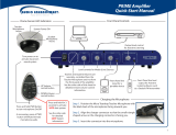
2. LOCATION OF THE RECEIVER/AMPLIFIER
• Before running wires to the 850iR or
plugging in, find a suitable, stable
location for the amplifier. Ideally, the
teacher should have ready access and
an electrical outlet should be within
six feet. The best possible
location for the 850iR
is in a media cabinet
with any existing audio/
video equipment.
• A good location would be on any stable
bookcase or shelf within 6 feet of an
electrical outlet. The optional Lightspeed
wall shelf (part #AC-800WB) is specifically
designed to support the 850iR.
•
Wires should be routed back directly to the amplifier, so
select a location that is free from obstructions that may
make routing wire difficult.
(Example: placing the 850iR near a whiteboard
or bulletin board would require the
wiring to be run an extra distance in
order to reach the amplifier.)
Best
Good
Avoid!

8 5 0 i R U s e r M a n u a l
850iR User Manual | 10
3. IR SENSOR INSTALLATION
Sensor location is very important for optimum performance of the 850iR Classroom Audio
System.
• BEST: On the ceiling at or near the middle of the classroom.
• GOOD: High and centered on the long wall.
• AVOID: Locations in corners, on walls at heights lower than 7 feet, or in places
where the line of sight is or could be obstructed.
Before adjusting the graphic equalizer refer to the intial set-up on page 18. Sometimes fine-tuning
is required to eliminate feedback.
Fine-tuning the Graphic Equalizer:
1. Slide
up and flip down the EQ cover door.
2. Walk the room listening for feedback (squealing).
3. Lower the 2K5 and/or 4K sliders if a high-pitched ring is present.
4. Lower the 400 and/or 700 sliders if a low-pitched ring is present.
5. Reduce volume if feedback is still present.
Helpful Hint
Good placement
Best placement
Avoid!

8 5 0 i R U s e r M a n u a l
11 | 850iR User Manual
1. Lift the ceiling tile nearest the grid rail in
your desired sensor location. Guide one
side of the C-clip over one edge of the
grid rail. Providing firm support to the
back of the grid rail with one hand (to
prevent bending), firmly and carefully
snap the second side of the C-clip over
the edge of the rail.
2. Uncoil sensor wire. Connect one
end of the sensor cable to the plug on
the sensor. Secure wire overhead and
route it back to
the system.
3. Connect the other end of the sensor
cable into one of the sensor inputs on
the back of the system.
IR SENSOR INSTALLATION (cont’d)
1. Screw the plastic mounting strip to a place
high on the wall or in the middle of the
solid ceiling. Mount the strip horizontally as
shown above.
2. Firmly snap the C-clip on the back of the
IR sensor onto the plastic mounting strip
with the sensor plug hanging down (if a wall
mount) or toward the receiver location (if
ceiling mount).
3. Uncoil the sensor wire. Screw one end of
the sensor cable to the plug on the sensor.
Route the wire back to the system, securing
it along
the way.
4. Connect the other end of the sensor cable
to one of the sensor inputs on the back of
the system.
Suspended Ceiling Mount
Wall/Solid Ceiling Mount
sensor plug
c-clip
wall
mounting
strip

8 5 0 i R U s e r M a n u a l
850iR User Manual | 12
4. SPEAKER INSTALLATION
1. Locate the speaker installation instructions packed
with your speaker(s).
2. Follow instructions and mount speaker(s).
3. Return to this manual to complete the set up of your
system.
CNXQ (x 1)
DRQ (x 4)WMQ (x 4)
NXQ (x 1)
CNXQ (x 1)
MCQ (x 1)

8 5 0 i R U s e r M a n u a l
13 | 850iR User Manual
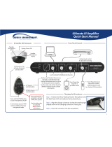
The 850iR is designed to integrate with multiple audio
sources allowing other instructional technologies to be
clearly heard throughout the classroom.
5. AUDIO INTEGRATION
850iR BLOCK DIAGRAM
Projector
DVD/VCR
Speaker(s)
IR Sensor
Teacher’s
Microphone
Projector
Audio In
Audio Out
IR Transmission
Video In
Audio Out
Audio Out
Video Out
Video Out
VGA Out
850iR

8 5 0 i R U s e r M a n u a l
850iR User Manual | 14
Below are instructions on how to connect an external audio device like a TV/
VCR, CD/DVD or computer directly into the 850iR.
AUDIO INTEGRATION (cont’d)
1. Ensure the power switch is in the “OFF” position and all front panel volume controls
are turned fully counter-clockwise.
2. Connect
a patch cable (not included from
the audio source into the corresponding
input jack on the rear panel of the 850iR.
3. With both the 850iR and audio source power on, adjust the
corresponding volume control until the desired level is achieved.
NOTE! Be careful to not to set the volume too high, as this can distort
the speaker and potentially cause damage.
SPEAKER OUTPUTS
250 400
700
1K 1 K4
2K5
4K
6K
+10
0
-10
OFF
OFF
OFF
OFF
ON
ON ON
ON
VOL.
ADJ.
ALD OUT
AUX OUT
VOL.
ADJ.
COMPUTER
AUDIO INPUTS
TV/VCR CD/DVD
800iX
INPUT
PAGING INPUT
ADJ
DC POWER CHARGERS
24VDC
L L R R
SENSOR INPUTS
SENSOR
SHORT
1 2 3
4
LES 850iR Classroom Amplification System
1
2
LES 850iR Classroom Amplification System
3

8 5 0 i R U s e r M a n u a l
15 | 850iR User Manual
2. Ensure speaker wire connections are secure and not frayed. Under normal conditions, each
speaker volume control should remain in the center position.
1. Ensure the power switch is in the “OFF” position and all front panel volume controls are turned
fully counter-clockwise.
6. FINALIZING CONNECTIONS
Use conduit to
protect wires.
• Conduit is the best
means to keep the
wires/cables out of
sight and safe from
wear. (Conduit is
not included.)
Helpful Hint
SPEAKER OUTPUTS
250 4 00
700
1K 1K4
2K5
4K
6K
+10
0
-10
OFF
OFF
OFF
OFF
ON
ON ON
ON
VOL.
ADJ.
ALD OUT
AUX OUT
VOL.
ADJ.
COMPUTER
AUDIO INPUTS
TV/VCR CD/DVD
800iX
INPUT
PAGING INPUT
ADJ
DC POWER CHARGERS
24VDC
L L R R
SENSOR INPUTS
SENSOR
SHORT
1 2 3
4
1
2
LES 850iR Classroom Amplification System
/