LightSpeed Technologies CAT 885 User manual
- Category
- Supplementary music equipment
- Type
- User manual

User Manual
Classroom Audio System


TABLE OF CONTENTS
SECTION 1: 4 Important Safety Instructions
Overview 5 System Components and Unpacking
7 Optional Components
8 Front Panel Controls
9 Rear Panel Controls
11 ISR Controls and Connections
12 REDMIKE Controls and Connections
13 Cradle Charger Controls and Connections
SECTION 2: 14
Step 1. Location of the Amplifier
Set-up & Use 15 Step 2. ISR Sensor Installation
18 Step 3. Speaker Installation
18 Step 4A. Connect the Power Supply
19 Step 4B. ISR Connection
20 Step 4C. Speaker Connection(s)
21 Step 4D. Audio Input Connections
22 Step 5. Audio Integration
23 Step 6. Charging the REDMIKE
24 Step 7. Operating the REDMIKE
25 Step 8. Initial Set-up Speaker Audio
26 Step 9. Setting Mic Priorities
27 Output to Assistive Listening Device
28 Using the REDMIKE to Amplify External
Audio Equipment
SECTION 3: 29 REDMIKE VC: Controls and Connections
Optional Accessories 30 Charging
30 Initial Set-Up
32 LT-71: Controls and Connections
33 Charging
34 Initial Set-Up
35 REDMIKE Share: Controls and Connections
36 Charging
37 Initial Set-Up
38 iR Media Connector: Initial Setup
39 Audio Integration
39 Other Optional Accessories
SECTION 4: 40 Troubleshooting Guide
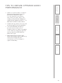
Troubleshooting 41 Tips to Obtain Optimal Audio Performance
SECTION 5: 42 Warranty Statement
Warranty &
Specifications
43 Safety Warnings and Certifications
44 System Specifications

IMPORTANT SAFETY INSTRUCTIONS
1. Read these instructions.
2. Keep these instructions.
3. Heed all warnings.
4. Follow all instructions.
5. Do not use the apparatus
near water.
6. Clean only with dry cloth.
7. Do not block any ventilation
openings. Install in
accordance with the
manufacturer’s instructions.
8. Do not install near any heat
sources such as radiators,
heat registers, stoves, or
other apparatus (including
amplifiers) that produce
heat.
9. Do not defeat the safety
purpose of the polarized
or grounding-type plug.
A polarized plug has two
blades with one wider than
the other. A grounding-
type plug has two blades
and a third grounding
prong. The wide blade or
the third prong is provided
for your safety. If the
provided plug does not fit
into your outlet, consult an
electrician for replacement
of the obsolete outlet.
10. Protect the power cord
from being walked on
or pinched particularly
at plugs, convenience
receptacles, and the point
where they exit from the
apparatus.
11. Only use attachments/
accessories specified by the
manufacturer.
12. Use only with a cart,
stand, tripod, bracket or
table specified by the
manufacturer, or sold with
the apparatus. When a cart
is used, use caution when
moving the cart/apparatus
combination to avoid injury
from tip-over.
13. Unplug this apparatus
during lighting storms
or when unused for long
periods of time.
14. Refer all servicing to
qualified service personnel.
Servicing is required when
the apparatus has been
damaged in any way, such
as power-supply cord or
plug is damaged, liquid has
been spilled or objects have
fallen into the apparatus,
the apparatus has been
exposed to rain or moisture,
does not operate normally,
or has been dropped.
15. When the mains plug or
appliance coupler used
as the disconnect device,
it shall remain readily
operable.
16. Please keep the unit
in a good ventilation
environment.
17. The speaker on/off switches
will not disconnect the
main power when in the off
position.
4

5
1. Overview 2. Setup & Use
3. Optional
Accessories
4. Troubleshooting
5. Warranty, Safety
& Specifications
SECTION 1:
OVERVIEW
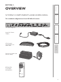
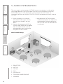
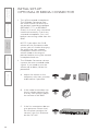
SYSTEM COMPONENTS AND UNPACKING
The standard configuration of the CAT 885 will contain:
ISR Infrared
Sensor/Receiver
and Cable
Charging Cradle and
Power Supply
REDMIKE®
Classroom
Microphone
CAT 885 Amplifier
Amplifier Power
Supply

6
1. Overview 2. Setup & Use
3. Optional
Accessories
4. Troubleshooting
5. Warranty, Safety
& Specifications
Speakers and Speaker Wire
Systems can be configured with a variety of different speaker types,
including the following:
Standard Components
AMP-885 Audio amplifier/mixer
PS-24V-2.5 24V/2.5A power supply for CAT 885
RX-ISR Infrared sensor/receiver with mounting bracket
CA-P5E50 50’ plenum-rated Cat 5e cable
RMT REDMIKE classroom microphone with battery
BA-NH2A27 AA NiMH rechargeable sensing battery for REDMIKE
AC-RMLC2 REDMIKE lavaliere cord
BC-RMCC REDMIKE cradle charger
PS-5V-1.0 5V/1.0A power supply for cradle charger
SPEAKERS Contact Lightspeed at 800.732.8999 for speaker info
NXQ (x 1)
WMQ (x 4)
DRQ (x 4)
MCQ (x 1)

7
1. Overview 2. Setup & Use
3. Optional
Accessories
4. Troubleshooting
5. Warranty, Safety
& Specifications
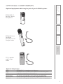
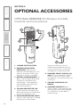
OPTIONAL COMPONENTS
Optional equipment which may be part of your CAT 885 system:
REDMIKE® VC
Volume Control
Microphone
LT- 71
LT-71 LightMic
and Charger
Cable
Optional Components
RMV REDMIKE VC microphone with battery
RMS REDMIKE Share handheld microphone with battery pack
LT71 LightMic microphone with batteries
BA-NH2A27 AA NiMH rechargeable sensing battery for REDMIKE
BA-NH2APK NiMH rechargeable battery pack for REDMIKE Share
BA-NH1 AA NiMH rechargeable battery for LT71 (2 per microphone)
REDMIKE Share
Handheld
Microphone and
Charger Cable

8
1. Overview 2. Setup & Use
3. Optional
Accessories
4. Troubleshooting
5. Warranty, Safety
& Specifications
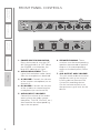
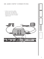
FRONT PANEL CONTROLS
1. POWER SWITCH/INDICATOR:
Press this button to turn the CAT
885 ON (pushed in) or OFF. When
the POWER is switched on, the
blue LED indicator will light.
2. AUDIO INDICATORS: These
lights flash red when audio (voice)
from the microphone is detected.
3. A VOLUME: Controls the volume
of the teacher microphone (set to
channel A).
4. B VOLUME: Controls the volume
of the student or second teacher
microphone (set to channel B).
5. AUDIO INPUT VOLUMES:
Control the volume of the audio
coming from the media source
(computer, TV/VCR, CD/DVD, etc.)
connected to the corresponding
input the rear panel.
6. SPEAKER ZONING: These
switches turn the corresponding
speakers (connected to speaker
outputs in the corresponding
zones on the back panel) ON or
OFF.
7. ALD OUTPUT AND VOLUME:
This jack sends audio to external
equipment such as an assistive
listening device (Personal FM
System) or recording device.
Use the volume control to set
the optimum signal level for the
device.
2
5
1
4
2
3
7
6

9
1. Overview 2. Setup & Use
3. Optional
Accessories
4. Troubleshooting
5. Warranty, Safety
& Specifications
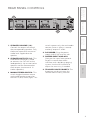
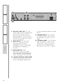
REAR PANEL CONTROLS
1
2
3
4
5
6
1. SPEAKER VOLUME (1-6):
Controls the output volume of
the corresponding speaker. Fully
clockwise represents maximum
audio level supplied to the
speaker.
2. SPEAKER OUTPUTS (1-6): This
euro-block connector is used
to connect the CAT 885 to the
loudspeaker(s). Up to two 8-ohm
speakers can be connected to
each output (maximum of 12
8-ohm speakers).
3 MONO/STEREO SWITCH: This
switch toggles between mono
and stereo speaker output for
channels 5 (left) and 6 (right). This
switch impacts only the multimedia
sources (voice is always is mono)
and only outputs 5 and 6.
4. DC POWER: Plug the power
supply (24V/2.5A) into this jack.
5. PAGING INPUT AND ADJ:
Connect the input from optional
PageFirst sensor here when
interface with a buildings paging
system. Use the ADJ control to
adjust the sensitivity if needed.
6. TEACHER VOICE PRIORITY: This
3-position switch activates the
Teacher Voice Priority function

10
1. Overview 2. Setup & Use
3. Optional
Accessories
4. Troubleshooting
5. Warranty, Safety
& Specifications
7
8
9
10
11
12
7. AUX OUT AND VOL: This jack
sends audio to external equipment
such as an assistive listening
device (Personal FM System) or
recording device. Use the volume
control to set the optimum signal
level for the device.
8. 805iX INPUT: This input jack
allows for interface with the
Lightspeed 805iX wireless
microphone system, which adds
two additional microphone
channels.
9. AUDIO INPUTS: These
connections accept an audio
signal from other technology so
all multimedia can be distributed
evenly throughout the classroom.
10. 8-BAND GRAPHIC EQUALIZER:
These sliding controls allow the
installer to properly equalize the
system to produce optimum audio
quality.
11. SENSOR INPUT: The infrared
microphone audio from the ISR is
connected to this input via Cat 5
cable.
12. SENSOR SHORT: This LED glows
red when there is a short in the
ISR or cable. The system will not
operate, but is protected from
damage when the LED is lighted.

11
1. Overview 2. Setup & Use
3. Optional
Accessories
4. Troubleshooting
5. Warranty, Safety
& Specifications
INFRARED SENSOR/RECEIVER (ISR)
CONNECTIONS
1. POWER INDICATOR: This light
will glow blue when the ISR is
receiving power from the CAT 885.
2. A/B IR INDICATORS: These lights
glow when the corresponding
microphone (set to channel A or
B) is turned on and transmitting.
A steady light indicates a strong
signal.
3. SENSOR OUT: Connect the Cat 5
sensor cable to this connection to
send audio from the microphones
to the CAT 885 amplifier.
4. IR EXPANSION: Connect up to
three passive IR sensors (IR-SR70F)
to this connection for larger
classrooms. For more than one
additional sensor a 3-way coax
splitter is required (HS3).
1
2
3
4

12
1. Overview 2. Setup & Use
3. Optional
Accessories
4. Troubleshooting
5. Warranty, Safety
& Specifications
1. POWER BUTTON: Press this
button to turn the REDMIKE ON,
press again to turn it OFF (mute).
2. POWER/LOW BATTERY
INDICATOR: A BLUE light
indicates the REDMIKE is on and
fully charged. A RED light indicates
a charge is needed.
3. BATTERY COMPARTMENT: To
access the battery compartment,
slide the door downward. The
battery should only be replaced
by a Lightspeed AA rechargeable
sensing battery (part # BA-
NH2A27).
4. YELLOW PROTECTIVE TAB:
Slide the battery compartment
door open to remove this
disposable protective tab before
use. NOTE: do not attempt to
remove the tab without first
opening the compartment door, as
it may tear, leaving fragments.
5. AUDIO/MICROPHONE INPUT:
Use this input to plug in a laptop,
MP3 player or other audio
source to wirelessly transmit
audio to be played through the
system. Alternatively, an external
microphone can be connected.
6. CHANNEL SELECT SWITCH
(CH A/B): This switch allows
for selection between Channel
A or B. If you are using a single
microphone, we recommend using
Channel A.
7. CHARGER CONTACTS (+ -):
These contacts interface with the
charging tabs in the BC-RMCC
cradle charger for daily charging.
Simply place the REDMIKE in the
charger.
REDMIKE CONTROLS AND CONNECTIONS
1
2
3
5
6
7
S
l
i
d
e
b
a
t
t
e
r
y
d
o
o
r
o
p
e
n
R
e
m
o
v
e
t
a
b
b
e
f
o
r
e
u
s
e
4

13
1. Overview 2. Setup & Use
3. Optional
Accessories
4. Troubleshooting
5. Warranty, Safety
& Specifications
1. CHARGE INDICATORS: The light
glows RED while the REDMIKE is
charging. When fully charged, the
light will glow GREEN. A blinking
RED light indicates that no battery
is sensed, (REDMIKE Yellow
Protective Tab may not have been
completely removed—see page
5, item 4.) A blinking Green LED
means a non- Lightspeed battery
has been installed (possibly an
alkaline battery).
2. DC POWER PORT: Connect the
5V/1.0A DC power cord here.
3. OPTIONAL CHARGING PORT:
Plug the charging cord for the
optional LT-71 or the REDMIKE
Share microphones here.
CRADLE CHARGER CONTROLS AND
CONNECTIONS
1
2
3

14
1. Overview 2. Setup & Use
3. Optional
Accessories
4. Troubleshooting
5. Warranty, Safety
& Specifications
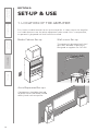
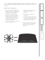
First, find a suitable location to set-up the amplifier. It is best to put the amplifier
in a stable location near the other equipment to be used. If this is not possible,
an optional Lightspeed wall shelf can be installed.
Media Cabinet Set-up
The optional Lightspeed wall shelf
(part #AC-800WB) is specifically
designed to support the CAT 885.
Wall-mount Set-up
SECTION 2:
SET-UP & USE
1. LOCATION OF THE AMPLIFIER
Avoid Separated Set-ups
Components should be located
together. Wires should be routed
directly back to the amplifier.

15
1. Overview 2. Setup & Use
3. Optional
Accessories
4. Troubleshooting
5. Warranty, Safety
& Specifications
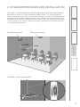
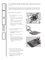
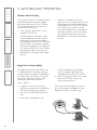
2. IR SENSOR/RECEIVER (ISR) INSTALLATION
Next, find a suitable location for the ISR. Poor location will cause substandard
performance of the CAT 885 Classroom Audio System. The ISR should be as
high as possible in the room – the ceiling is the best location, centered along the
longest wall in the room. When possible, use a conduit to protect the wires (not
included). Poor choices for placement are corners, on walls at heights lower than
7 feet (2 meters), or in places where the line of sight from the ISR to the receiver
is or could be obstructed.
Good placement
Conduit is Recommended
Best placement
Avoid!

16
1. Overview 2. Setup & Use
3. Optional
Accessories
4. Troubleshooting
5. Warranty, Safety
& Specifications
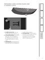
2. IR SENSOR/RECEIVER (ISR) INSTALLATION
CONT’D
Once you find a suitable location for the ISR, follow these instructions to mount
it. There are different instructions for mounting depending on if the ISR will be
mounted to a suspended ceiling grid or secured to a wall / solid vertical surface.
1. Attach the bracket to the ceiling
tile grid (t-bar).
a. Slide the tabs onto the outsides
of the t-bar, starting with one
corner.
b. Attach the second tab around
the other side of the t-bar.
c. Repeat with the other side of
the bracket so it is connected at
all four points.
2. Slide the ISR onto the bracket until
it “clicks” into place.
a. Guide the mounting rails onto
the bracket, oriented as
pictured.
b. Once secure, the ISR locks into
place.
c. To remove the ISR, press the
release bar down and slide the
ISR off the bracket. (We need to
label the “release bar” on the
ISR Image that shows “clip
guide”)
3. Uncoil the Cat 5 sensor cable.
Connect one end of the cable to
the ISR. Secure wire overhead and
route it back to the system.
4. Connect the other end of the Cat
5 sensor cable into the SENSOR
INPUT jack on the CAT 885
amplifier.
Suspended Ceiling Mount
clip connects to t-bar on ceiling

17
1. Overview 2. Setup & Use
3. Optional
Accessories
4. Troubleshooting
5. Warranty, Safety
& Specifications
1. Screw the bracket to a place high
on the wall or in the middle of the
solid ceiling. Mount the bracket
horizontally as shown above.
2. Uncoil the Cat 5 sensor cable.
Connect one end of the cable to
the ISR. Route the wire back to
the CAT 885 amplifier, securing
it along with way using surface
raceway where possible.
3. Slide the ISR onto the bracket until
it “clicks” into place.
2. IR SENSOR/RECEIVER (ISR) INSTALLATION
CONT’D
Wall/Solid Ceiling Mount
a. Guide the mounting rails onto
the bracket, oriented as
pictured.
b.Once secure, the ISR locks
into place.
c. To remove the ISR, slide a ruler
or screwdriver behind the ISR to
press the release bar down and
slide the ISR off the bracket
4. Connect the other end of the Cat
5 sensor cable into the SENSOR
INPUT jack on the CAT 885
amplifier.

18
1. Overview 2. Setup & Use
3. Optional
Accessories
4. Troubleshooting
5. Warranty, Safety
& Specifications
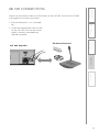
3. SPEAKER INSTALLATION
1. Locate the speaker installation
instructions packed with your
speaker(s).
2. Follow instructions and mount
speaker(s).
3. Return to this manual to complete
the set up of your system.
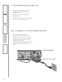
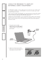
4A. CONNECT THE POWER SUPPLY
1. Ensure the power button is
depressed in the OFF position.
2. Connect the DC end of the power
supply to the black power jack
labeled DC POWER.
3. Connect the black AC power cable
from the power supply to a wall
outlet.
CAT 885 Amplifier
DC Power Source Cable

19
1. Overview 2. Setup & Use
3. Optional
Accessories
4. Troubleshooting
5. Warranty, Safety
& Specifications
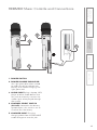
4B. ISR CONNECTION
Check the connections from the ISR Sensor to the CAT 885. Ensure the CAT 885
is plugged into an electrical outlet.
CAT 885 Amplifier
1. Ensure the power is still switched
off.
2. Check the connection from the ISR
to the CAT 885. Ensure the sensor
cable is securely attached and
locked into place.
ISR Sensor/Receiver

20
1. Overview 2. Setup & Use
3. Optional
Accessories
4. Troubleshooting
5. Warranty, Safety
& Specifications
1. Ensure the power switch is in the
off position
2. Ensure speaker wire connections
are secure and not frayed. Under
normal conditions, each speaker
volume control should remain at
maximum level (fully clockwise).
4C. SPEAKER CONNECTIONS
Page is loading ...
Page is loading ...
Page is loading ...
Page is loading ...
Page is loading ...
Page is loading ...
Page is loading ...
Page is loading ...
Page is loading ...
Page is loading ...
Page is loading ...
Page is loading ...
Page is loading ...
Page is loading ...
Page is loading ...
Page is loading ...
Page is loading ...
Page is loading ...
Page is loading ...
Page is loading ...
Page is loading ...
Page is loading ...
Page is loading ...
Page is loading ...
Page is loading ...
Page is loading ...
Page is loading ...
Page is loading ...
-
 1
1
-
 2
2
-
 3
3
-
 4
4
-
 5
5
-
 6
6
-
 7
7
-
 8
8
-
 9
9
-
 10
10
-
 11
11
-
 12
12
-
 13
13
-
 14
14
-
 15
15
-
 16
16
-
 17
17
-
 18
18
-
 19
19
-
 20
20
-
 21
21
-
 22
22
-
 23
23
-
 24
24
-
 25
25
-
 26
26
-
 27
27
-
 28
28
-
 29
29
-
 30
30
-
 31
31
-
 32
32
-
 33
33
-
 34
34
-
 35
35
-
 36
36
-
 37
37
-
 38
38
-
 39
39
-
 40
40
-
 41
41
-
 42
42
-
 43
43
-
 44
44
-
 45
45
-
 46
46
-
 47
47
-
 48
48


LightSpeed Technologies CAT 885 User manual
- Category
- Supplementary music equipment
- Type
- User manual
Ask a question and I''ll find the answer in the document
Finding information in a document is now easier with AI
Related papers
-
LightSpeed Technologies FP 100 User manual
-
-
-
Lightspeed CAT 860 User manual
-
-
-
-
-
-
Other documents
-
 DogWatch Receiver Charging Supplement Operating instructions
-
Klip Xtreme KSS-600 Datasheet
-
-
Coomber Microphone User manual
-
 Audio Enancement Prime Quick start guide
-
 Audio Enancement Prime Quick start guide
-
 Audio enhancement ULTIMATE III Quick start guide
-
-
TeachLogic IMA-232 User guide
-
Pyle Professional DJ Laptop Stand User manual


