Page is loading ...

O P E R A T I N G I N S T R U C T I O N S
SIM2000ST-E
Sensor Integration Machine

Described product
SIM2000ST-E
Manufacturer
SICK AG
Erwin-Sick-Str. 1
79183 Waldkirch
Germany
Legal information
This work is protected by copyright. Any rights derived from the copyright shall be
reserved for SICK AG. Reproduction of this document or parts of this document is
only permissible within the limits of the legal determination of Copyright Law. Any modi‐
fication, abridgment or translation of this document is prohibited without the express
written permission of SICK AG.
The trademarks stated in this document are the property of their respective owner.
© SICK AG. All rights reserved.
Original document
This document is an original document of SICK AG.
2
O P E R A T I N G I N S T R U C T I O N S | SIM2000ST-E 8025454//2020-11-03 | SICK
Subject to change without notice

Contents
1 About this document........................................................................ 5
1.1 Information on the operating instructions.............................................. 5
1.2 Explanation of symbols............................................................................ 5
1.3 Further information................................................................................... 6
1.4 SICK service.............................................................................................. 6
2 Safety information............................................................................ 7
2.1 General safety notes................................................................................ 7
2.2 Intended use............................................................................................. 7
2.3 Improper use............................................................................................. 7
2.4 Internet protocol (IP) technology.............................................................. 8
2.5 Limitation of liability................................................................................. 8
2.6 Modifications and conversions................................................................ 8
2.7 Requirements for skilled persons and operating personnel.................. 9
2.8 Operational safety and particular hazards.............................................. 9
3 Product description........................................................................... 11
3.1 Device view................................................................................................ 11
3.2 Functionality.............................................................................................. 11
3.3 SICK AppSpace......................................................................................... 12
3.4 Preset Ethernet interfaces....................................................................... 12
4 Transport and storage....................................................................... 14
4.1 Transport................................................................................................... 14
4.2 Transport inspection................................................................................. 14
4.3 Storage...................................................................................................... 14
5 Mounting............................................................................................. 15
5.1 Overview of mounting procedure............................................................. 15
5.2 Scope of delivery....................................................................................... 15
5.3 Preparing for mounting............................................................................. 15
5.4 Mounting the device................................................................................. 15
6 Electrical installation........................................................................ 17
6.1 Important notes........................................................................................ 17
6.2 Preparing the electrical installation......................................................... 17
6.3 Preparing the cables................................................................................. 17
6.4 Overview of connections.......................................................................... 18
6.5 Pin allocation of the connections............................................................ 19
6.6 Connecting peripheral devices................................................................ 23
6.7 Connecting voltage supply....................................................................... 24
7 Commissioning.................................................................................. 25
7.1 Preparatory commissioning..................................................................... 25
CONTENTS
8025454//2020-11-03 | SICK O P E R A T I N G I N S T R U C T I O N S | SIM2000ST-E
3
Subject to change without notice

8 Operation............................................................................................ 26
8.1 Status LEDs............................................................................................... 26
9 Maintenance...................................................................................... 31
9.1 Cleaning..................................................................................................... 31
9.2 Maintenance plan..................................................................................... 31
10 Decommissioning............................................................................. 32
10.1 Disposal..................................................................................................... 32
11 Technical data.................................................................................... 33
11.1 Features.................................................................................................... 33
11.2 Interfaces.................................................................................................. 33
11.3 Mechanics and electronics...................................................................... 34
11.4 Ambient data............................................................................................. 35
12 Annex.................................................................................................. 36
12.1 Dimensional drawings.............................................................................. 36
12.2 Licenses.................................................................................................... 36
CONTENTS
4
O P E R A T I N G I N S T R U C T I O N S | SIM2000ST-E 8025454//2020-11-03 | SICK
Subject to change without notice

1 About this document
1.1 Information on the operating instructions
These operating instructions provide important information on how to use devices from
SICK AG.
Prerequisites for safe work are:
•
Compliance with all safety notes and handling instructions supplied.
•
Compliance with local work safety regulations and general safety regulations for
device applications
The operating instructions are intended to be used by qualified personnel and electrical
specialists.
NOTE
Read these operating instructions carefully to familiarize yourself with the device and its
functions before commencing any work.
The operating instructions are an integral part of the product. Store the instructions
in the immediate vicinity of the device so they remain accessible to staff at all times.
Should the device be passed on to a third party, these operating instructions should be
handed over with it.
These operating instructions do not provide information on operating the machine or
system in which the device is integrated. For more information, refer to the operating
instructions of the specific machine or system.
1.2 Explanation of symbols
Warnings and important information in this document are labeled with symbols. Sig‐
nal words introduce the instructions and indicate the extent of the hazard. To avoid
accidents, damage, and personal injury, always comply with the instructions and act
carefully.
DANGER
… indicates a situation of imminent danger, which will lead to a fatality or serious
injuries if not prevented.
WARNING
… indicates a potentially dangerous situation, which may lead to a fatality or serious
injuries if not prevented.
CAUTION
… indicates a potentially dangerous situation, which may lead to minor/slight injuries if
not prevented.
NOTICE
… indicates a potentially harmful situation, which may lead to material damage if not
prevented.
NOTE
… highlights useful tips and recommendations as well as information for efficient and
trouble-free operation.
ABOUT THIS DOCUMENT 1
8025454//2020-11-03 | SICK O P E R A T I N G I N S T R U C T I O N S | SIM2000ST-E
5
Subject to change without notice

1.3 Further information
NOTE
Further documentation for the device can be found on the online product page at:
•
www.sick.com/SIM2000
There, additional information has been provided depending on the product, such as:
•
Model-specific online data sheets for device types, containing technical data,
dimensional drawing, and specification diagrams
•
EU declarations of conformity for the product family
•
Dimensional drawings and 3D CAD dimension models of the device types in
various electronic formats
•
Other publications related to the devices described here
•
Publications dealing with accessories
1.4 SICK service
If you require any technical information, our SICK Service will be happy to help. To find
your agency, see the final page of this document.
NOTE
Before calling, make a note of all type label data such as type code, serial number, etc.,
to ensure faster processing.
1 ABOUT THIS DOCUMENT
6
O P E R A T I N G I N S T R U C T I O N S | SIM2000ST-E 8025454//2020-11-03 | SICK
Subject to change without notice

2 Safety information
2.1 General safety notes
The following safety notes must always be observed regardless of specific application
conditions:
•
The device must only be mounted, commissioned, operated, and maintained by
professionally qualified safety personnel.
•
Electrical connections with peripheral devices must only be made when the volt‐
age supply is disconnected.
•
The device is only to be operated when mounted in a fixed position.
•
The device voltage supply must be protected in accordance with the specifications.
•
The specified ambient conditions must be observed at all times.
•
The electrical connections to peripheral devices must be screwed on or clamped
correctly.
•
The cooling fins or fan - if present - must not be covered or restricted in their
functionality.
•
The pin assignment of pre-assembled cables must be checked and adjusted if
necessary.
•
These operating instructions must be made available to the operating personnel
and kept ready to hand.
2.2 Intended use
The device is a programmable control and evaluation unit for Sensors and cameras.
The device also acts as a link between system and plant controls, and the connected
terminal devices. The device is mainly used in an industrial environment in production,
testing, and control. Other applications are possible depending on the device-specific
properties.
The device is programmed on a PC by using the development environment software
SICK AppSpace. Depending on the application, a browser-based, graphical user inter‐
face (HMI) can be created, which provides opportunities defined by the application
developer to influence an application at operator level.
The device connection to the peripherals is established by means of a range of indus‐
trial fieldbuses and other interfaces.
The device offers various interfaces for controlling, programming, and operating pur‐
poses, which can be activated as necessary via development environments, control
systems (programmable logic controllers), or applications.
However, configuration, programming, and control requires various technical skills,
depending on how the device is connected and used.
2.3 Improper use
Any use outside of the stated areas, in particular use outside of the technical specifica‐
tions and the requirements for intended use, will be deemed to be incorrect use.
•
The device does not constitute a safety component in accordance with the respec‐
tive applicable safety standards for machines.
•
The device must not be used in explosion-hazardous areas, in corrosive environ‐
ments or under extreme environmental conditions.
•
Any use of accessories not specifically approved by SICK AG is at your own risk.
SAFETY INFORMATION 2
8025454//2020-11-03 | SICK O P E R A T I N G I N S T R U C T I O N S | SIM2000ST-E
7
Subject to change without notice

WARNING
Danger due to improper use!
Any improper use can result in dangerous situations.
Therefore, observe the following information:
■
Product should be used only in accordance with its intended use.
■
All information in these operating instructions must be strictly observed.
■
Shut down the product immediately in case of damage.
2.4 Internet protocol (IP) technology
NOTE
SICK uses standard IP technology in its products. The emphasis is placed on availability
of products and services.
SICK always assumes the following prerequisites:
•
The customer ensures the integrity and confidentiality of the data and rights
affected by its own use of the aforementioned products.
•
In all cases, the customer implements the appropriate security measures, such as
network separation, firewalls, virus protection, and patch management.
2.5 Limitation of liability
Relevant standards and regulations, the latest technological developments, and our
many years of knowledge and experience have all been taken into account when
compiling the data and information contained in these operating instructions. The
manufacturer accepts no liability for damage caused by:
■
Non-adherence to the product documentation (e.g., operating instructions)
■
Incorrect use
■
Use of untrained staff
■
Unauthorized conversions or repair
■
Technical modifications
■
Use of unauthorized spare parts, consumables, and accessories
With special variants, where optional extras have been ordered, or owing to the latest
technical changes, the actual scope of delivery may vary from the features and illustra‐
tions shown here.
NOTE
Programmable device
The Sensor Integration Machine (SIM) is a programmable device.
Therefore, the respective programmer is responsible for his/her programming perfor‐
mance and the resulting operating principle of the device.
The liability and warranty of SICK AG is limited to the device specification (hardware
functionality and any programming interfaces) according to the agreed conditions.
Therefore, SICK AG is not liable, among other things, for damages that are caused by
programming of the customer or third parties.
2.6 Modifications and conversions
NOTICE
Modifications and conversions to the device may result in unforeseeable dangers.
2 SAFETY INFORMATION
8
O P E R A T I N G I N S T R U C T I O N S | SIM2000ST-E 8025454//2020-11-03 | SICK
Subject to change without notice

Interrupting or modifying the device or SICK software will invalidate any warranty claims
against SICK AG. This applies in particular to opening the housing, even as part of
mounting and electrical installation.
2.7 Requirements for skilled persons and operating personnel
WARNING
Risk of injury due to insufficient training.
Improper handling of the device may result in considerable personal injury and material
damage.
■
All work must only ever be carried out by the stipulated persons.
This product documentation refers to the following qualification requirements for the
various activities associated with the device:
■
Instructed personnel have been briefed by the operator about the tasks assigned
to them and about potential dangers arising from improper action.
■
Skilled personnel have the specialist training, skills, and experience, as well as
knowledge of the relevant regulations, to be able to perform tasks delegated to
them and to detect and avoid any potential dangers independently.
■
Electricians have the specialist training, skills, and experience, as well as knowl‐
edge of the relevant standards and provisions, to be able to carry out work on
electrical systems and to detect and avoid any potential dangers independently.
The electrician must comply with the provisions of the locally applicable work
safety regulation.
The following qualifications are required for various activities:
Table 1: Activities and technical requirements
Activities Qualification
Mounting, maintenance
■
Basic practical technical training
■
Knowledge of the current safety regulations in the workplace
Electrical installation,
device replacement
■
Practical electrical training
■
Knowledge of current electrical safety regulations
■
Knowledge of the operation and control of the devices in their
particular application
Commissioning, configura‐
tion
■
Basic knowledge of the computer operating system used
■
Basic knowledge of the design and setup of the described
connections and interfaces
■
Basic knowledge of data transmission
Operation of the device for
the particular application
■
Knowledge of the operation and control of the devices in their
particular application
■
Knowledge of the software and hardware environment for the
particular application
2.8 Operational safety and particular hazards
Please observe the safety notes and the warnings listed here and in other chapters
of this product documentation to reduce the possibility of risks to health and avoid
dangerous situations.
SAFETY INFORMATION 2
8025454//2020-11-03 | SICK O P E R A T I N G I N S T R U C T I O N S | SIM2000ST-E
9
Subject to change without notice

WARNING
Electrical voltage!
Electrical voltage can cause severe injury or death.
■
Work on electrical systems must only be performed by qualified electricians.
■
The power supply must be disconnected when attaching and detaching electrical
connections.
■
The product must only be connected to a voltage supply as set out in the require‐
ments in the operating instructions.
■
National and regional regulations must be complied with.
■
Safety requirements relating to work on electrical systems must be complied with.
WARNING
Risk of injury and damage caused by potential equalization currents!
Improper grounding can lead to dangerous equipotential bonding currents, which may
in turn lead to dangerous voltages on metallic surfaces, such as the housing. Electrical
voltage can cause severe injury or death.
■
Work on electrical systems must only be performed by qualified electricians.
■
Follow the notes in the operating instructions.
■
Install the grounding for the product and the system in accordance with national
and regional regulations.
2.8.1 LED RG0
The product is fitted with LEDs in risk group 0. The accessible radiation from these
LEDs does not pose a danger to the eyes or skin.
2 SAFETY INFORMATION
10
O P E R A T I N G I N S T R U C T I O N S | SIM2000ST-E 8025454//2020-11-03 | SICK
Subject to change without notice

3 Product description
3.1 Device view
ä
9
ß
ã
à
á
â
1
2
3
4
5
6
7
8
1
X1 – POWER: connections for the device voltage supply
2
X2 – IO LINK MASTER: connections for IO-Link and/or GPIO
3
X3 – OUTPUT: connections for digital switching outputs
4
X4 – INPUT A: connections for digital switching inputs A
5
X5 – INPUT B: connections for digital switching inputs B
6
X6 – SERIAL A: serial connections A
7
X7 – SERIAL B: serial connections B
8
X8 – CAN: connections for SICK CAN sensor network with termination resistor which can
be activated
9
X9 ... X10 - FIELDBUS: 2 connections for Ethernet-based fieldbuses
ß
X11 ... X14 - ETHERNET: 4 Ethernet connections
à
USB connection
á
2 x microSD card slot
â
Device status indicators
ã
Function selector switch (configurable by SensorApp)
ä
Battery compartment
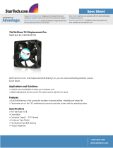
3.2 Functionality
The SIM2000ST-E Sensor Integration Machine – part of the SICK AppSpace eco-system
– is opening up new possibilities for application solutions.
Data from SICK sensors such as 1D / 2D code sensors and VMS4xx / 5xx for detecting
object geometry can be imported, evaluated, archived, and transmitted. Four fast Ether‐
net interfaces are available for sensors. In addition, data from SICK LiDAR scanners
can be read, merged into a point cloud, evaluated, archived, and transmitted. The SIM
enables SICK picoCam and midiCam as well as any GigE Vision/GenICAM compliant
cameras to be used.
Other sensors can be integrated via IO-Link, for example for distance and height mea‐
suring purposes. Depending on the application, additional sensors can be connected
for the read cycle, for detecting the object distance (e.g., MLG, as an alternative to the
VMS4xx / 5xx), and for generating the increment signal.
PRODUCT DESCRIPTION 3
8025454//2020-11-03 | SICK O P E R A T I N G I N S T R U C T I O N S | SIM2000ST-E
11
Subject to change without notice

Fieldbus and Ethernet interfaces with OPC-UA and MQTT provide data preprocessed in
“dual talk” (edge computing) for the controller and for cloud computing. In addition, the
SIM can be integrated into a SICK CAN sensor network.
Thanks to the high-performance multi-core processor and a dedicated I/O processor
core, the device allows fast sensor data processing and the handling of input and
output signals in real time.
The SICK AppSpace open software platform enables tailor-made application programs
to be developed for demanding applications.
The HMI and data visualization features can be provided on any browser-enabled
notebook/PC or tablet. The app is developed in the SICK AppStudio SDKs.
SIM2000ST-E
Versorgungsspannung
Netzanschluss
System ICR890
CAN-Bus
HOST
Lesetakt
Fördergeschwindigkeit
Lichtgitter MLG
Objektabstand
(optional)
VMS4xx/5xx CLV690
Objektgeometrie
3.3 SICK AppSpace
Detailed instructions on the SICK AppStudio as well as programming the device can be
found at supportportal.sick.com.
3.4 Preset Ethernet interfaces
NOTE
Preset IP addresses of the ETHERNET interfaces:
•
ETHERNET 1: 192.168.0.1
•
ETHERNET 2: 192.168.1.1
•
ETHERNET 3: 192.168.2.1
•
ETHERNET 4: 192.168.3.1
3 PRODUCT DESCRIPTION
12
O P E R A T I N G I N S T R U C T I O N S | SIM2000ST-E 8025454//2020-11-03 | SICK
Subject to change without notice

When expanding the Ethernet interfaces with one or more switches, it is essential to
use only jumbo-frame compatible Ethernet switches. Switches limited to just 100 Mb/s
do not support the data packet mode used by cameras and can cause transmission
errors.
Changing the IP addresses
The individual IP addresses can be changed using the SICK “SOPAS-ET” PC tool.
PRODUCT DESCRIPTION 3
8025454//2020-11-03 | SICK O P E R A T I N G I N S T R U C T I O N S | SIM2000ST-E
13
Subject to change without notice

4 Transport and storage
4.1 Transport
For your own safety, please read and observe the following notes:
NOTICE
Damage to the product due to improper transport.
■
The device must be packaged for transport with protection against shock and
damp.
■
Recommendation: Use the original packaging as it provides the best protection.
■
Transport should be performed by trained specialist staff only.
■
The utmost care and attention is required at all times during unloading and
transportation on company premises.
■
Note the symbols on the packaging.
■
Do not remove packaging until immediately before you start mounting.
4.2
Transport inspection
Immediately upon receipt in Goods-in, check the delivery for completeness and for any
damage that may have occurred in transit. In the case of transit damage that is visible
externally, proceed as follows:
■
Do not accept the delivery or only do so conditionally.
■
Note the scope of damage on the transport documents or on the transport com‐
pany's delivery note.
■
File a complaint.
NOTE
Complaints regarding defects should be filed as soon as these are detected. Damage
claims are only valid before the applicable complaint deadlines.
4.3 Storage
Store the device under the following conditions:
■
Do not store outdoors.
■
Store in a dry area that is protected from dust.
■
Do not expose to any aggressive substances.
■
Protect from sunlight.
■
Avoid mechanical shocks.
■
Storage temperature: see "Technical data", page 33.
■
For storage periods of longer than 3 months, check the general condition of all
components and packaging on a regular basis.
4 TRANSPORT AND STORAGE
14
O P E R A T I N G I N S T R U C T I O N S | SIM2000ST-E 8025454//2020-11-03 | SICK
Subject to change without notice

5 Mounting
5.1 Overview of mounting procedure
NOTE
The mounting procedure described here for the device meets the requirements for use
in the target system.
Additional or different requirements may become necessary in the laboratory and dur‐
ing preparation, and should be taken into account as necessary, see "Commissioning",
page 25. If you have any questions or anything remains unclear in this regard, please
contact our service team.
•
Install the device.
•
Connect the cables.
•
Connecting peripheral devices.
•
Connecting the voltage supply.
5.2 Scope of delivery
•
SIM 2000ST-E
•
4 x grounding screw
•
4 x toothed lock washer
•
Safety note
NOTE
The device is equipped with spring terminals as standard.
5.3 Preparing for mounting
Mounting requirements
•
Select the mounting site:
Plan space requirements and sufficient distance from other devices.
Be aware of the possibility of heat dissipation.
•
Unpack the device and allow to acclimatize to avoid formation of condensation.
Preparing for mounting
1. Place the device at the mounting site.
2. Mark the mounting holes.
3. Proceed to drill the mounting holes.
5.4 Mounting the device
Mounting the device
1. Set the device on the mounting site.
2. Fasten device with at least two M5 screws (max. 6 Nm) on opposite device sides
and corresponding washers.
NOTICE
Use self-locking or lock nuts on mounting sites that are exposed to vibrations to prevent
the holding plates from loosening.
MOUNTING 5
8025454//2020-11-03 | SICK O P E R A T I N G I N S T R U C T I O N S | SIM2000ST-E
15
Subject to change without notice

BATTERY
CR 1632
0 = LFT LOCK
1 = LFT UNLOCK
SEAL
SIM2000ST-E
DEVICE READY
SYSTEM READY
RESULT
microSD 1microSD 2USB
L
LINK
ACT
LINK
ACT
LINK
ACT
LINK
ACT
LINK
ACT
LINK
X9
FIELDBUS P1
X10
FIELDBUS P2
X11
ETH 1
X12
ETH 2
X13
ETH 3
X14
ETH 4
ACT
BF / NS / ERR SF / NS / RUN
1 CO1 DI1 CO2 DI2 2 1 1GND
GND
GND
GND
OUT1
IN1+
IN1+
IN2+
IN2+
IN3+
IN4+
OUT2
OUT3
OUT4
GND
GND
GND
GND
24V
CQ1
DI1
GND
24V
CQ2
DI2
GND ISO
24V
24V
GND ISO
24V
GND ISO
IN5+
IN5+
IN6+
IN6+
IN7+
IN8+
R1+/RxD1
R2+/RxD2
R1+
GND
R2+
T1+/TxD1
T2+/TxD2
T1+
GND
GNDGND
CAN LCAN L
CAN HCAN H
T2+
R3+/RxD3
R4+/RxD4
R3+
GND ISO
R4+
T3+/TxD3
T4+/TxD4
T3+
GND ISO
T4+
GND ISO
24V
24V
GND ISO
24V
GND ISO
GND
SHIELD
24V IN1
SHIELD
24V IN2
ISO
S1
ISO
S2
GND
2 3 4 2 3 4 5GND RX1 TX1 RX2 TX2 RX3 TX3 RX4 TX4
TERM ACT
6 7 8
1 2 3
4 5 6
1 2 3
4 5 6
1 2 3
5 6 7
4
8
1 2 3
5 6 7
4
8
1 2 3
7 8 9
4
10
5
11
6
12
1 2 3
7 8 9
4
10
5
11
1 2 3
6 7 8
4
9
5
10
1 2 3
6 7 8
4
9
5
10
6
12
X1
POWER
X2
IO LINK MASTER
X3
OUPUT
X4
INPUT A
X5
INPUT B
X6
SERIAL A
X7
SERIAL B
X8
CAN
5 MOUNTING
16
O P E R A T I N G I N S T R U C T I O N S | SIM2000ST-E 8025454//2020-11-03 | SICK
Subject to change without notice

6 Electrical installation
6.1 Important notes
WARNING
Risk of injury and damage caused by electrical current!
Due to equipotential bonding currents, incorrect earthing can lead to the following
dangers and faults: Voltage is applied to the metal housing, cable fires due to cable
shields heating up, the product and other devices become damaged.
■
Generate the same ground potential at all grounding points.
■
Ground the equipotential bonding via the functional ground connection with a low
impedance (use standard cable lug with M3 hole).
NOTICE
Device damage due to improper supply voltage!
■
Only operate the device with the specified supply voltage.
■
The voltage supply and all connected signals must meet the requirements for
extra-low voltages with safe separation (SELV) as specified in EN 61010. The
external voltage supply of the device must bridge a short-term power interruption
of 20 ms in order to meet the requirements of EN 60204-1.
■
Only devices that are also supplied with safety extra-low voltage must be con‐
nected.
NOTE
Layout of data cables
■
Use screened data cables with twisted-pair wires.
■
Implement the screening design correctly and completely.
■
To avoid interference, e.g. from switching power supplies, motors, clocked drives,
and contactors, always use cables and layouts that are suitable for EMC.
■
Do not lay cables over long distances in parallel with power supply cables and
motor cables in cable channels.
6.2
Preparing the electrical installation
To carry out the electrical installation, you will need:
•
Connection cables for the peripheral devices, including the corresponding data
sheets
•
Voltage supply cable
•
If customers assemble the cables: crimping tool, ferrules, soldering iron, and other
installation material
6.3 Preparing the cables
For a list of cables suitable for use with the device, see: supportportal.sick.com or
www.sick.com.
Customer assembly of the cables is only necessary in special cases. Ensure a sufficient
length of cable is provided, e.g., for strain-relief clamps.
ELECTRICAL INSTALLATION 6
8025454//2020-11-03 | SICK O P E R A T I N G I N S T R U C T I O N S | SIM2000ST-E
17
Subject to change without notice

NOTICE
Risk of damage/malfunction due to incorrect PIN assignment
Incorrect wiring of the male connectors/female connectors can lead to damage to or
malfunctions in the system.
■
Observe data sheets provided by the cable manufacturer.
■
Observe the pin assignment.
6.4 Overview of connections
9 ß
â1 3 ã 4 ã ã 72
à
á
á
5 6 8
1
X1 - POWER
2
X2 - IO LINK MASTER
3
X3 - OUTPUT
4
X4 - INPUT A
5
X5 - INPUT B
6
X6 - SERIAL A
7
X7 - SERIAL B
8
X8 - CAN (SICK CAN sensor network)
9
X9 ... X10 - fieldbus
ß
X11 ... X14 - ETHERNET
à
USB connection (Micro-B, for configuration/diagnostics)
á
2 x microSD card slot
â
Functional earth
ã
Cable shield connection (e.g. via screening clamps using the supplied M3 screws)
6.4.1 Functional earth connection
Figure 1: Alternative FE connection
The functional earth (FE) is connected either via the housing or via an FE connection
with cable lug.
Alternative FE connection
Screw connection of the alternative functional earth connection
6 ELECTRICAL INSTALLATION
18
O P E R A T I N G I N S T R U C T I O N S | SIM2000ST-E 8025454//2020-11-03 | SICK
Subject to change without notice

•
Screw: M3 × 15
Suitable cable lugs
•
Forked cable lug or ring cable lug
•
Width ≤ 10 mm
•
Hole diameter for screw: typically 3.1 mm
The functional earth must be connected in a low-inductance manner and with an
adequate cross-section while keeping the cable length as short as possible.
6.5 Pin allocation of the connections
6.5.1 X1 - POWER
PIN Signal Function
1 Shield Shield
2 GND GND (ground)
3 24 V IN1 Supply voltage 1
4 Shield Shield
5 GND GND (ground)
6 24 V IN2 Supply voltage 2
Additional notes:
•
Permanent load: max. 5.4 A (IN1 + IN2)
•
Supply voltage: 24 V ± 20%
•
Maximum power consumption: 20 W (internal)
•
Maximum power output of all connections: 100 W
•
Supply voltage IN1 and IN2 can be set up redundantly.
Observe the requirements for the design of overcurrent protective devices accord‐
ing to EN 61010.
6.5.2 X2 - IO LINK MASTER
PIN Signal Function
1 24 V Supply voltage
2 GND GND (ground)
3 CQ1 IO-Link data or GPIO
4 DI1 Digital switching input
5 24 V Supply voltage
6 GND GND (ground)
7 CQ2 IO-Link data or GPIO
8 DI2 Digital switching input
Additional notes:
•
C/Qn: IO-Link data or configurable GPIO (not insulated)
•
DIn: digital input (non-insulated)
•
2x IO-Link master
•
Max. 0.7 A total output for 24 V supply voltage connections
•
Switching output:
°
Max. output 100 mA
°
Min. high output logic level: VCC – 3 V
°
Max. low output logic level: 3 V
°
Push-pull
ELECTRICAL INSTALLATION 6
8025454//2020-11-03 | SICK O P E R A T I N G I N S T R U C T I O N S | SIM2000ST-E
19
Subject to change without notice

°
Max. IO-Link output frequency: 230 kHz
°
Max. IO output frequency: 5 kHz (all switching inputs and outputs used)
•
Switching input:
°
Min. high input logic level: 12 V
°
Max. low input logic level: 4 V
°
Max. IO-Link input frequency: 230 kHz
°
Max. IO input frequency: 5 kHz (all switching inputs and outputs used)
•
The digital inputs and outputs are not reverse polarity protected. The voltage at the
X1 inputs and outputs must never be higher than the 24 V supply voltage of the
device to prevent feedback.
6.5.3 X3 - OUTPUT
PIN Signal Function
1 OUT1 Digital switching output
2 OUT2 Digital switching output
3 OUT3 Digital switching output
4 OUT4 Digital switching output
5 GND Reference potential for switching outputs
6 GND Reference potential for switching outputs
7 GND Reference potential for switching outputs
8 GND Reference potential for switching outputs
Additional notes:
•
OUT1 to OUT4: Non-insulated push-pull outputs with max. 100 mA
•
Min. high output logic level: VCC - 3 V
•
Max. frequency: 1 kHz (1 kohm load resistance)
6.5.4 X4 – INPUT A
Table 2: X4 - INPUT A
Pin Signal Function
1 IN1+ Isolated digital switching input
2 IN1+ Isolated digital switching input
3 IN2+ Isolated digital switching input
4 IN2+ Isolated digital switching input
5 IN3+ Isolated digital switching input
6 IN4+ Isolated digital switching input
7 24 V Non-insulated supply voltage for external sensors
8 GND ISO (X4) Insulated reference potential for switching inputs (X4)
*
9 24 V Non-insulated supply voltage for external sensors
10 GND ISO (X4) Insulated reference potential for switching inputs (X4)
*
11 24 V Non-insulated supply voltage for external sensors
12 GND ISO (X4) Insulated reference potential for switching inputs (X4)
*
*
S1 switch in GND position: Reference potential also for 24 V (X4)
Additional notes:
•
IN1 and IN2 are designed with redundancy
•
Max. 0.7 A total output for all 24 V supply voltage connections
•
Min. high input logic level: 12 V
6 ELECTRICAL INSTALLATION
20
O P E R A T I N G I N S T R U C T I O N S | SIM2000ST-E 8025454//2020-11-03 | SICK
Subject to change without notice
/