Page is loading ...

DO GUIDE
Installing the HD-RX3-C
Install the HD-RX3-C in either of the following ways:
• Onto a at surface
• Onto a rack rail
Installing the HD-RX3-C onto a Flat Surface
Using four mounting screws (not included), attach the HD-RX3-C to a at surface. Mounting onto a
wall is shown below.
Installing the HD-RX3-C onto a Rack Rail
Install the HD-RX3-C onto the front or rear rail of a rack as follows:
1. Position the left or right mounting anges of the device so that the holes align with the holes in
the rack rail.
2. Secure the device to the rack rail using two rack mounting screws (not included).
Installing the HD-TX3-C onto a Flat Surface
Install the HD-TX3-C onto a at surface as follows:
1. Using the appropriate hardware (not included), attach the included mounting bracket to a at
surface.
2. Using the two included #6-32 x 3/16-inch Phillips head screws, attach the device to the bracket.
Installing the HD-TX3-C onto a Rack Rail
Install the HD-TX3-C onto the front or rear rail of a rack as follows:
1. Position the device horizontally so that the holes of the left or right mounting ange align with the
holes in the rack rail.
2. Secure the device to the rack rail using two rack mounting screws (not included).
HD-EXT3-C
4K HDMI
®
over HDBaseT
®
Extender with IR and RS-232
DO Verify the SW1 DIP Switch Setting on the HD-TX3-C
The Crestron
®
HD-TX3-C includes the SW1 DIP switch, which controls the hot plug detect (HPD)
signal. Before installing the HD-TX3-C, locate the DIP switch on the unit and verify that the switch is
set in the ON position (default setting). When the switch is set to ON, the HPD signal is sent from the
display device on the HD-RX3-C to the source device on the HD-TX3-C.
NOTE: The OFF position of the SW1 DIP switch is reserved for factory use only.
DO Install the Device
Install the HD-TX3-C and HD-RX3-C as appropriate for the application.
Installing the HD-TX3-C
Install the HD-TX3-C in any of the following ways:
• Into a 1-gang electrical box
• Onto a at surface
• Onto a rack rail
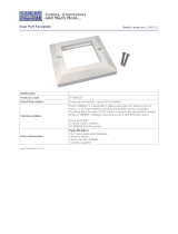
Installing the HD-TX3-C into a 1-Gang Electrical Box
NOTE: The recommended depth of the electrical box (not included) is a minimum of 2.5 inches
(64 mm).
NOTE: Before installing the HD-TX3-C into an electrical box, connect the ground wire to earth
ground and connect the HDBaseT
®
OUT port. Refer to the "DO Connect the Device" section for
additional information.
Install the HD-TX3-C into a 1-gang electrical box as follows:
1. Using the two included #6-32 x 3/4-inch combo head screws, attach the HD-TX3-C to the
electrical box.
2. Attach the desired decorator style faceplate (faceplate and hardware not included).
DO Check the Box
QUANTITY PRODUCT COLOR PART NUMBER
1 Bracket (for Interface Module) Black 2016054
2 Connector, 2-Pin 2003574
2 Connector, 3-Pin 2003575
1 Power Pack, 24 Vdc 0.75 A, 100-240 Vac 2045865
2 Screw, 06-32 x 3/16", Pan Head, Phillips Black 2007203
2 Screw, 06-32 x 3/4", Truss Head, Combo Black 20 09211
ON

DO GUIDE
DOC. 7811B (2044422) 12.16
Specications subject to change without notice.
DO Connect the Device
Make connections to the HD-TX3-C and HD-RX3-C as required for the application.
Connecting the HD-TX3-C and HD-RX3-C to Ground
Connect the ground wire on the HD-TX3-C and the chassis ground lug on the HD-RX3-C to earth
ground (building steel).
Connecting the HDMI and Control Ports on the HD-TX3-C
Connect the HDMI
®
and control ports on the HD-TX3-C as follows:
• Using an HDMI cable (not included), connect the HDMI IN port to the HDMI output port of the
audio/video source.
• Connect the IR IN or COM control port or both as follows:
• IR IN: Using an IR cable (not included), connect the 2-pin terminal block of the IR IN port to
the IR output port of the control system.
• COM (RS-232): Using a data communications cable (not included), connect the 3-pin
terminal block of the COM port to the COM port of the control system.
Connecting the HDMI and Control Ports on the HD-RX3-C
Connect the HDMI and control ports on the HD-RX3-C as follows:
• Using an HDMI cable (not included), connect the HDMI OUT port to the HDMI input port of the
receiving device.
• Connect the IR OUT or COM control port or both as follows:
• IR OUT: Using the Crestron IRP2 emitter (sold separately), connect the 2-pin terminal block
of the IR OUT port to the IR sensor window of the device to be controlled.
• COM (RS-232): Using a data communications cable (not included), connect the 3-pin
terminal block of the COM port to the COM port of the device to be controlled.
Connecting the HDBaseT Ports on the HD-TX3-C and HD-RX3-C
Using Crestron DM-CBL-ULTRA, Crestron DM-CBL-8G, or generic CAT5e cable (not included),
connect the HDBaseT OUT port on the HD-TX3-C to the HDBaseT IN port on the HD-RX3-C.
Connecting the Power Connector on the HD-TX3-C or HD-RX3-C
Only one 24 Vdc power pack (included) is required to power both the HD-TX3-C and the HD-RX3-C.
Connect the power pack to the 24 Vdc power connector on either the HD-TX3-C device or the
HD-RX3-C device—do not connect a power pack to both devices. Power is transmitted over the cable
that connects the HDBaseT ports on the HD-TX3-C and HD-RX3-C.
NOTE: The HD-TX3-C and HD-RX3-C are not HDBaseT PoE compatible; that is, the devices cannot
be powered by—or supply power to—another HDBaseT device.
As of the date of manufacture, the product has been tested and found to comply with specications for CE marking.
This product is Listed to applicable UL Standards and requirements by Underwriters Laboratories Inc.
Ce produit est homologué selon les normes et les exigences UL applicables par Underwriters Laboratories Inc.
Federal Communications Commission (FCC) Compliance Statement
This device complies with part 15 of the FCC Rules. Operation is subject to the following two conditions:
(1) This device may not cause harmful interference, and (2) this device must accept any interference received, including interference that may cause undesired operation.
CAUTION: Changes or modications not expressly approved by the manufacturer responsible for compliance could void the user’s authority to operate the equipment.
NOTE: This equipment has been tested and found to comply with the limits for a Class B digital device, pursuant to part 15 of the FCC Rules. These limits are designed to provide reasonable protection
against harmful interference in a residential installation. This equipment generates, uses and can radiate radio frequency energy and, if not installed and used in accordance with the instructions, may
cause harmful interference to radio communications. However, there is no guarantee that interference will not occur in a particular installation.
If this equipment does cause harmful interference to radio or television reception, which can be determined by turning the equipment off and on, the user is encouraged to try to correct the interference
by one or more of the following measures:
• Reorient or relocate the receiving antenna.
• Increase the separation between the equipment and receiver.
• Connect the equipment into an outlet on a circuit different from that to which the receiver is connected.
• Consult the dealer or an experienced radio/TV technician for help.
Industry Canada (IC) Compliance Statement
CAN ICES-3(B)/NMB-3(B)
The specic patents that cover Crestron products are listed at www.patents.crestron.com. The product warranty can be found at www.crestron.com/warranty.
Certain Crestron products contain open source software. For specic information, please visit www.crestron.com/opensource.
Crestron and the Crestron logo are either trademarks or registered trademarks of Crestron Electronics, Inc., in the United States and/or other countries. HDBaseT and the HDBaseT Alliance logo are either trademarks or registered trademarks of the HDBaseT Alliance in the United States and/or
other countries. HDMI and the HDMI logo are either trademarks or registered trademarks of HDMI Licensing LLC in the United States and/or other countries. Other trademarks, registered trademarks, and trade names may be used in this document to refer to either the entities claiming the marks
and names or their products. Crestron disclaims any proprietary interest in the marks and names of others. Crestron is not responsible for errors in typography or photography.
This document was written by the Technical Publications department at Crestron.
©2016 Crestron Electronics, Inc.
DO Learn More
Visit the website for additional information and the latest rmware updates. To learn more about this product, use a QR reader application on
your mobile device to scan the QR image.
Crestron Electronics
15 Volvo Drive, Rockleigh, NJ 07647
888.CRESTRON | www.crestron.com
HD-TX3-C
ground wire
HD-RX3-C
ground lug
COM
HDMI OUTIR OUT
G S
G
TX
RX
G
AV
SOURCE
CONTROL
SYSTEM
PWR/
LINK
IR IN
HDMI
IN
COM
G
S
RX
TX
G
DISPLAY
COM
HDMI OUTIR OUT
G
S
G
G
TX
RX
OUT
HDBaseT IN
24V
0.75A
24 V
0.75A
PWR
POWER
PACK
To HD-TX3-C
or
HD-RX3-C
HDBaseT IN
PWR
24 V
0.75A
24V
0.75A
OUT
/