Mircom LT-6906 UL TX3-CX Card Access System User manual
- Category
- Networking
- Type
- User manual

Version 2 UL Listed TX3-CX Card Access System Installation Manual 1
LT-6906 Copyright August 2019
TX3 Series
UL LISTED TX3-CX CARD ACCESS
SYSTEMS
Installation Manual

2 UL Listed TX3-CX Card Access System Installation Manual Version 2
LT-6906 Copyright August 2019
Copyright August 2019 Mircom Inc.
All rights reserved.
Mircom UL Listed TX3-CX Card Access System Installation and Operation Manual v.2
Microsoft, MS-DOS, Windows, and Windows 2000/NT/XP/Vista/7/8/10 are either registered
trademarks or trademarks of Microsoft Corporation in the United States and/or other countries.
Mircom
25 Interchange Way
Vaughan, Ontario
L4K 5W3
905.660.4655
Fax:905.660.4113

Version 2 UL Listed TX3-CX Card Access System Installation Manual 3
LT-6906 Copyright 2019
Contents
1 Welcome 6
1.1 Introducing the TX3-CX Card Access System 6
1.2 Applications 7
1.3 Installer Responsibilities 8
1.4 Network Setup 8
1.5 About this Manual 12
1.6 Contact Us 12
2 Configurable Features 13
2.1 Inputs 13
2.2 Correlations 14
2.3 Access Criteria 16
2.4 Timers 23
2.5 Schedules 24
2.6 Holidays 25
2.7 System Status 25
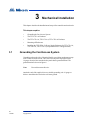
3 Mechanical Installation 26
3.1 Grounding the Card Access System 26
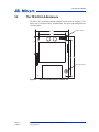
3.2 The TX3-CX-2-A Enclosure 27
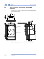
3.3 The TX3-CX-4-A, TX3-CX-6-A, TX3-CX-8-A Enclosure 28
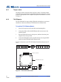
3.4 Mounting all Enclosures 29
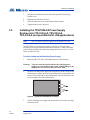
3.5 Installing the TX3-PS24-5A Power Supply Enclosure for TX3-CX-4-A,
TX3-CX-6-A, TX3-CX-8-A (not permitted in UL 294 applications) 30
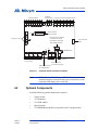
4 Setup of the Card Access Controller 33
4.1 Controller Board Description 33
4.2 Optional Components 35
4.3 Power Supply Options 40
4.4 TX3-PS24-5A Power Supply (not permitted in UL 294 applications) 41
4.5 RS-485 43
4.6 USB Port 45
4.7 Inputs 45
4.8 Outputs 49
4.9 Card Readers 52
4.10 Setting DIP Switches SW2 54
4.11 Setting Jumpers 56
4.12 Turning on the Controller 56
4.13 Updating Firmware 56
4.14 Beginning Configuration 57
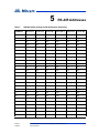
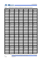
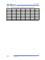
5 RS-485 Addresses 59
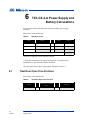
6 TX3-CX-2-A Power Supply and Battery Calculations 62
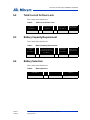
6.1 Total Door Open Time Per Hour 62
6.2 Total Current for Door Lock 63
6.3 Battery Capacity Requirement 63


Version 2 UL Listed TX3-CX Card Access System Installation Manual 5
LT-6906 Copyright 2019
List of Figures
Figure 1 Basic Card Access System 9
Figure 2 Card Access System using an RS-485 network 9
Figure 3 Card Access System using an Ethernet TCP/IP
network 10
Figure 4 Card Access System using both Ethernet and RS-485
networks 11
Figure 5 Enclosure dimensions for TX3-CX-2-A 27
Figure 6 Enclosure dimensions for TX3-CX-4-A, TX3-CX-6-A,
TX3-CX-8-A 28
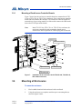
Figure 7 Installation of the controllers in the TX3-CX-4-A, TX3-
CX-6-A, TX3-CX-8-A enclosure 29
Figure 8 Inside the TX3-PS24-5A enclosure 30
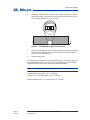
Figure 9 TX3-PS24-5A voltage selection switch 31
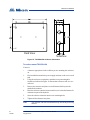
Figure 10 TX3-PS24-5A enclosure dimensions 32
Figure 11 Controller board connection locations 35
Figure 12 IP module board location 36
Figure 13 TX3-USB-AD board location 37
Figure 14 Controller board battery wring 38
Figure 15 Modem board location 39
Figure 16 Modem module telephone connectors 40
Figure 17 Controller board power supply 41
Figure 18 TX3-PS24-5A terminal block wiring 42
Figure 19 RS-485 Wiring for TX3-CX-2-A 44
Figure 20 RS-485 Wiring for TX3-CX-4-A 44
Figure 21 RS--485 Wiring for TX3-CX-6-A 45
Figure 22 RS-485 Wiring for TX3-CX-8-A 45
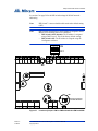
Figure 23 Controller board input terminals 46
Figure 24 Input terminal sample connections 46
Figure 25 Input - supervised for open 48
Figure 26 Input - supervised for short 48
Figure 27 Input - supervised for open and short 49
Figure 28 Controller output terminal sample connections 51
Figure 29 Outputs 7 and 8 sample connections 52
Figure 30 Controller board card reader connectors 53
Figure 31 Location of jumpers JW1 to JW8 and switches SW1
and SW2 55

6 UL Listed TX3-CX Card Access System Installation Manual Version 2
LT-6906 Copyright 2019
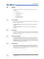
1 Welcome
This manual provides information about the installation and operation of the
TX3-CX Card Access System, and must be read in its entirety before beginning
any installation work.
Installation must be performed by a qualified technician and must adhere to the
standards and special notices set by the local regulatory bodies.
Note: Mircom periodically updates panel firmware and
Configurator Software to add features and correct any minor
inconsistencies. For information about the latest firmware or
software visit the Mircom website at www.mircom.com.
Warning: The Card Access System must be grounded by a qualified
electrician. An improperly grounded unit can result in
equipment malfunction and electrical shock.
This chapter explains
• Introducing the TX3-CX Card Access System
• Applications
• Installer Responsibilities
•Network Setup
• About this Manual
• Contact Us
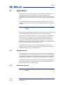
1.1 Introducing the TX3-CX Card Access System
The TX3-CX Card Access System is part of the Mircom suite of products that
provide building ready monitoring, control and integrated security solutions for
use in the high end multi-tenant residential market.
The Card Access System addresses the need within today’s high end multi-
tenant residential market for an easy-to-use tenant access system and an easy-to-
use configuration utility.
This manual provides the technician with information about the installation and
configuration of the Card Access System and explains how to configure various
components for a new system, including the modification of an existing system.

Welcome
Version 2 UL Listed TX3-CX Card Access System Installation Manual 7
LT-6906 Copyright 2019
1.2 Applications
Mircom's Card Access System consists of a controller, two card readers and
configuration software. The controller can accept at the same time, a
combination of card readers with different formats to control two access points
or doors. The Card Access System can set elevator usage if elevator controls are
used.
A number of different card readers are supported, such as the TX3-CX-REC
Wiegand wireless receiver, all of which are configurable using the Configurator
software.
Note: Only the 26-bit Wiegand SIA standard format is evaluated to
UL 294.
The Card Access System can be used in a stand-alone or networked environment
using a standard RS-485, daisy chain peer-to-peer network arrangement.
This network can consist of only the card access controller or a combination of
Touch Screens, Lobby Control Units, Elevator Restriction Units and Card
Access Units. Up to 63 units can be networked on any RS-485 network or
subnetwork. Valid RS-485 network addresses range from 1 to 63. One of the
networked units with a real time clock, such as Touch Screen, Lobby Control or
Card Access must have their network address set to 1.
If an Ethernet network is used, you can connect more than 63 units to your
system. If you use an Ethernet network with RS-485 subnetworks, each RS-485
subnetwork can have 63 devices connected to it.
1.2.1 Wiegand interface
The Wiegand interface is a wiring standard for card readers for establishing the
connections between a card reader and the Card Access System. This interface is
a serial interface requiring 7 to 10 conductors for communications between the
reader and the controller. This interface also supplies 12V power to the reader.
The Wiegand compatible access card has 26 bits of information embedded onto
the card. The card reader reads and registers the card information and sends it
back to the controller in a serial bit stream.
1.2.2 Card Access System
Note: Only the 26-bit Wiegand SIA standard format is evaluated to
UL 294.

8 UL Listed TX3-CX Card Access System Installation Manual Version 2
LT-6906 Copyright 2019
Welcome
The Mircom Card Access System supports a proprietary 37-bit encoding
technology and a 26-bit SIA standard format, and consists of a maximum of 63
card access controllers networked together. Each card access controller can have
two card readers. The Card Access System provides an optional battery backup
and a real time clock.
The Card Access System integrates with the TX3 Telephone Access system by
utilizing a common network for both Telephone Access and Card Access
Systems.
A PC provides configuration and on-line monitoring of the Card Access System
and the Telephone Access System status. Once the system is configured, the PC
is not required.
1.3 Installer Responsibilities
The installation and setup must be done by a qualified technician. The technician
is responsible for installing all of the system components, connecting all of the
input and output wiring for the appropriate door entry systems, and ensuring that
the wiring adheres to the requirements of the system for proper operation using
the Configurator software.
1.4 Network Setup
The Card Access System can consist of either stand-alone card access controllers
or networked card access controllers. Networked card access controllers can
communicate over an RS-485 network, an Ethernet TCP/IP network, or a
combination of an Ethernet network with RS-485 subnetworks. All card access
controllers can communicate over RS-485. To communicate over an Ethernet
network you need at least one IP-enabled card access controller (called a Master
Node).
The TX3 Configurator software can connect to any of these network
configurations. How you connect to the network (that is, through TCP/IP, USB,
a modem, or the COM port) determines what devices you can configure on the
network using the TX3 Configurator. The different network configurations are
explained in the rest of this section.

Welcome
Version 2 UL Listed TX3-CX Card Access System Installation Manual 9
LT-6906 Copyright 2019
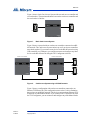
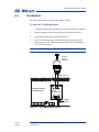
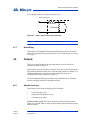
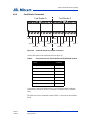
Figure 1 shows a basic Card Access System with one card access controller and
two card readers. The maximum distance between the card access controller and
the card readers is 500 feet.
Figure 1. Basic Card Access System
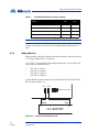
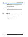
Figure 2 shows a network with two card access controllers connected to an RS-
485 network. The Card Access System can have up to 63 card access controllers
networked together. If you connect to any device on the RS-485 network (using
USB, a modem, or a COM port), you can also connect to and configure any other
device on the RS-485 network using the TX3 Configurator software.
Figure 2. Card Access System using an RS-485 network
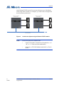
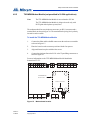
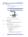
Figure 3 shows a configuration with card access controllers connected to an
Ethernet TCP/IP network. This configuration removes the 63 device limitation
that you have on an RS-485 network. The devices connected to an Ethernet TCP/
IP network are called Master Nodes. If you connect to the TCP/IP network with
the TX3 Configurator, you can connect to and configure any of the Master Nodes
Card Reader A Card Reader B
Card Access Controller
Card Reader B
Card Access Controller
Card Reader A
Card Reader B
Card Access Controller
Card Reader A
RS-485 Network

10 UL Listed TX3-CX Card Access System Installation Manual Version 2
LT-6906 Copyright 2019
Welcome
on the Ethernet TCP/IP network. If you connect directly to one of the Master
Nodes using USB, a modem, or a COM port, you will be able to configure that
device but not any other device.
Figure 3. Card Access System using an Ethernet TCP/IP network
Notes: In order for a panel to be a Master Node:
• It must be IP capable. Panels that are IP capable have “-A”,
“-B”, or “-C” at the end of their model names.
• It must have a TX3-IP IP Module installed if it is a Touch
Screen.
Card Reader B
Card Reader A
Card Reader B
Card Access Controller
(Master Node)
Card Reader A
Ethernet Network
Card Access Controller
(Master Node)

Welcome
Version 2 UL Listed TX3-CX Card Access System Installation Manual 11
LT-6906 Copyright 2019
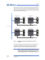
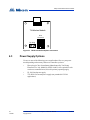
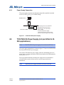
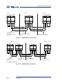
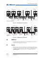
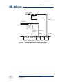
Figure 4 shows a Card Access System using an Ethernet network with RS-485
subnetworks. The card access controllers connecting to a Master Node’s RS-485
subnetwork are Slave Nodes to the Master Node. Each RS-485 subnetwork can
have up to 63 controllers connected to it; you can still have more than 63 Master
Nodes connected to the Ethernet network.
Figure 4. Card Access System using both Ethernet and RS-485
networks
If you connect to the Ethernet TCP/IP network with the TX3 Configurator, you
can configure any of the nodes in the system. If you connect directly to a
controller using USB, a modem, or a COM port, you will only be able to
configure devices that are on the same RS-485 subnetwork as that device.
Note: There can only be one Master Node on an RS-485 subnetwork.
That is, you cannot connect one RS-485 subnetwork to another
RS-485 subnetwork. However, if you want to connect to a
Touch Screen panel remotely over the Internet (for instance, to
RS-485 Subnetwork
Card Reader B
Card Access Controller
(Master Node)
Card Reader A
Card Reader B
Card Reader A
Card Access Controller
(Slave Node)
Card Reader B
Card Access Controller
(Master Node)
Card Reader A
Card Reader B
Card Reader A
Card Access Controller
(Slave Node)
RS-485 Subnetwork
Ethernet Network

12 UL Listed TX3-CX Card Access System Installation Manual Version 2
LT-6906 Copyright 2019
Welcome
configure Touch Screen options such as color and themes), the
Touch Screen panel must be set as an Master Node even if there
is no slave panel connected to it.
1.5 About this Manual
This manual covers the following models:
• TX3-CX-2-A Two Door Card Access Controller (includes 1 card access
controller board and 1 power transformer)
• TX3-CX-4-A Four Door Card Access Controller (includes 2 card access
controller boards, 1 TX3-IP IP Module, and 2 power transformers)
• TX3-CX-6-A Six Door Card Access Controller (includes 3 card access
controller boards, 1 TX3-IP IP Module, and 3 power transformers)
• TX3-CX-8-A Eight Door Card Access Controller (includes 4 card access
controller boards, 1 TX3-IP IP Module, and 4 power transformers)
• TX3-IP IP Module (allows a card access controller to connect to an
Ethernet TCP/IP network as a Master Node)
• TX3-USB-AD Kit (converts RS-485 signals to USB)
• TX3-MDM Modem Module (not permitted in UL 294 applications)
1.6 Contact Us
1.6.1 Canada and USA
Toll Free: 1-888-660-4655
Local: 905-660-4655
Fax: 905-660-4113
1.6.2 Website
http://www.mircom.com

Version 2 UL Listed TX3-CX Card Access System Installation Manual 13
LT-6906 Copyright 2019
2 Configurable Features
This chapter describes all the configurable features and their modes of operation,
and provides you with detailed information to let you configure the system using
the Configurator software.
For details on using the Configurator, see LT-995 TX3 Configuration and
Administration Manual.
This chapter explains
• Inputs
• Correlations
• Access Criteria
•Timers
• Schedules
• Holidays
• System Status
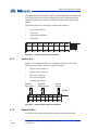
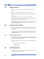
2.1 Inputs
Each card access controller has eight inputs to accommodate the following
special functions:
• Request to exit for reader A or B
• Door sense for reader A or B
• General purpose
2.1.1 Request to exit for reader A or B
When this input is active, the system unlocks the lock and the handicap lock for
either reader A or B. In addition, the Unlock time timer starts. When the Unlock
time timer expires or the door contact associated with this card reader becomes
active, the doors lock.
The input is associated with the ‘request to exit’ function.

14 UL Listed TX3-CX Card Access System Installation Manual Version 2
LT-6906 Copyright 2019
Configurable Features
2.1.2 Door sense for reader A or B
When the door is open this input is active and when the door is closed the input is
inactive. This input:
• senses if the door ever opened after it was unlocked as a result of access
being granted. If the door did not open even though the door was unlocked
for the programmed time duration, it is reported to the Configurator if
configured.
• senses a forced entry. If the door is locked and the door contact input
becomes active, the forced entry alarm activates. This can be changed by
selecting Disable forced entry alarm.
• senses if the door is held open. This happens when the door is unlocked
and the door contact becomes active but does not get inactivated before
the Unlock time timer or the Extended unlock time timer expires. At this
time the Door held open warning timer starts. If the door is still open
when this timer expires, a Door held open warning is reported to the
Configurator.
When the Door held open warning timer expires, the Door held open
alarm timer starts. When the Door held open alarm timer expires, a door
held open alarm is reported to the Configurator.
If the door closes during the time when the Door held open warning timer
or the Door held open alarm timer are active, the warning or alarm is
cancelled, and the Door open warning restored or Door open alarm
restored event is reported to the Configurator.
2.2 Correlations
The correlations function lets you establish specific relationships between panel
inputs (events) and outputs (actions), such as turning on a light when a door
opens. Correlations also allow you to specify these relationships to a schedule,
such as allowing access only during certain days and times of the week. A
maximum of 32 correlations is allowed.
2.2.1 Assigning events to access points
Assigning events to access points associates the access point with the event. The
Configurator lets you assign input events by labelling the following access
points:
• Reader A
• Reader B
• Inputs 1 to 8

Configurable Features
Version 2 UL Listed TX3-CX Card Access System Installation Manual 15
LT-6906 Copyright 2019
2.2.2 Events
Events are defined by the following inputs and reader states:
• Access is granted (from Reader A or B)
• Access is denied (from Reader A or B)
• Forced entry alarm (from Reader A or B)
• Door held open alarm (from Reader A or B)
• Door not open (from Reader A or B)
• Input is active (from Inputs 1 to 8)
• Unlock mode is on (from Reader A or B)
• Unlock mode is off (from Reader A or B)
• High security is on (from Reader A or B)
• High security is off (from Reader A or B)
2.2.3 Actions
An action is defined by the type of action that occurs for a specific event and
consists of the following:
• Turn ON output
• Turn OFF output
• Turn ON high security
• Turn OFF high security
2.2.4 Panels
Correlations can be applied to either one of the panels on your system, all of the
panels on your system, to a custom group of panels on your system (for TCP/IP
networks only), and across all panels on the network. They can occur on the local
panel, distributed panels or different types of panels (Card Access and Telephone
Access) on the network.
Note: Correlation signals cannot be transmitted by Touch Screen Master
Nodes. If you plan on setting up correlations either all of the panels
on your network or a custom group of panels, consult LT-995 for
instructions on selecting the Route IP Correlations checkbox.
2.2.5 Output
Actions are applied to an output on the panel(s) selected. This option specifies
which output.

16 UL Listed TX3-CX Card Access System Installation Manual Version 2
LT-6906 Copyright 2019
Configurable Features
2.2.6 Duration
The duration of the action is specified in minutes and seconds, or indefinitely.
2.2.7 Schedule
The schedule lets you specify when correlated events take effect.
2.3 Access Criteria
If connected to a PC, the Configurator software monitors the functional state of
inputs from all panels and devices, and senses the status of connected
components. Outputs are programmed for specific functionality, such as specific
delay and on/off times.
Granting access depends on different criteria, such as security precautions and
the access privileges granted the card holder. To prevent unauthorized access the
controller has various configurable features for determining the conditions and
type of access.
Access requirements are a function of schedule, holidays, security precautions
and access privileges. The parameters are configurable and allow for very
detailed system operation. For example access privileges may have
dependencies and consequently may be more suitable to run as a scheduled task.
The Configurator software lets you define and configure the various modes of
operation for managing access, defining inputs and assigning outputs. In order to
effectively use the Configurator you must understand these configurable
features.
The following features are configurable:
• Lock / Unlock
• High security
• PC decision required
• Facility code
•Card + PIN
• Anti-passback
• Temporary card
• Interlock
• Access Level
• Controller options
• Access point options
• Card options

Configurable Features
Version 2 UL Listed TX3-CX Card Access System Installation Manual 17
LT-6906 Copyright 2019
2.3.1 Lock / Unlock
An access point has one of the following lock status modes:
Lock Mode. When in lock mode the door is normally locked. Any valid access
card unlocks the door for the duration of a specified time interval according to:
• door unlock time
• extended unlock time
During this mode the red LED on the card reader associated with this access point
becomes active and turns green for the duration the door is unlocked.
Unlock Mode. When in unlock mode the door is unlocked. The green led on the
reader associated with this access point stays lit. During this mode the door sense
is not monitored for the following:
• door did not open
• door held open warning
• force entry alarm
2.3.1.1 Changing the lock/unlock mode
The lock/unlock mode is changed in one of the following three ways:
• an administrator using the Configurator can send a command to change
the lock mode
• an access card with lock/unlock privileges, if swiped twice in succession,
toggles between lock and unlock mode
• a schedule associated with the lock/unlock mode - when the associated
schedule is active, it changes to unlock mode and when the schedule is
inactive, it changes back to lock mode
Whenever the mode is changed from lock to unlock or from unlock to lock, the
beeper on the reader associated with this access point sends a distinct beep
indicating the mode is changed.
2.3.2 High security
The high security mode grants access to cards with the high security privilege.
This mode is changed as follows.
• if the access point is configured as high security then it is in high security
mode by default unless changed by the PC or card with high security
privilege
• if an access card with high security privilege is swiped four times in
succession, the mode toggles between high security on to high security off

18 UL Listed TX3-CX Card Access System Installation Manual Version 2
LT-6906 Copyright 2019
Configurable Features
• the Configurator software can change the mode from high security on to
high security off or from high security off to high security on
• an event correlated with a response to turn on or off the high security mode
The high security mode locks all doors in the unlocked mode.
Whenever the high security mode changes, the beeper on the reader associated
with this access point sends a distinct beep.
2.3.3 PC decision required
During this mode the decision to grant access is transferred to an attendant. Using
the PC the attendant grants or denies access. Only valid cards assigned with the
PC decision requirement are able to make this type of access request.
2.3.4 Facility code mode
Access cards consist of two codes; facility code and card code. The facility code
mode is designed for new installations where access cards are not programmed
into the database. When the facility code mode is enabled, cards with same
facility code are granted access.
The facility code can be set to any number. If a number is not chosen, it will
automatically default to “0” as a placeholder.
In this mode, the door is unlocked for the same period of time that as that of the
standard door unlock timer. This mode is configured for each access point.
2.3.5 Card + PIN
This mode provides another level of security during certain parts of the day.
During this mode not only a valid card is required for access but also a PIN code.
The PIN code is 1 to 4 digits long and is programmed for each card. 0 is not a valid
PIN code.
There is a schedule associated with this mode. When the schedule is enabled, the
mode is on and when the schedule is disabled, the mode is off.
This feature requires a card reader with a keypad.
2.3.6 Anti-passback
This mode prevents unauthorised users from getting access. During the anti-
passback period if a valid card is used at an access point, it cannot be re-used at
the same access point until the pre-programmed anti-passback timer expires.
After expiration of the timer, the user regains access.

Configurable Features
Version 2 UL Listed TX3-CX Card Access System Installation Manual 19
LT-6906 Copyright 2019
2.3.7 Temporary card
This type of card can be created by placing a usage counter on the card. Each time
the card is used, the usage counter is reduced by one. When the usage number
reaches zero, access is denied.
A usage counter of 255 indicates there is no restriction on use.
2.3.8 Interlock
This mode is typically used in a double door application to prevent unauthorised
access. During this mode the user presents the card at both doors. The second
door unlocks after presenting the card, if the first door is locked and closed.
If enabled door B cannot be unlocked until door A is locked and closed. Door A
cannot be unlocked until door B is locked and closed.
2.3.9 Access level
Creating an access level lets you define where and when to use a card, and set
elevator usage if elevator controls are used.
A maximum of 128 access levels are defined for each controller. A schedule is
associated with each access level for all the access points on the controller as
indicated by the following example.
Access level ID = 1
• for reader A schedule = Always
• for reader B schedule = Never
Access level ID = 2
• for reader A schedule = Office hours
• for reader B schedule = Always
If a card is assigned an access level 1 it means the user can have access to reader
A at all times but will not have access to reader B at any time.
If a card is assigned an access level 2 it means the user can have access to reader
A during the office hours and will have access to reader B all the time.
The option for elevator control exists for each access level. If elevator control is
enabled for a specific access level then swiping a card with that access level will
turn on the associated elevator relays. Which relays are activated can be specified
individually for each access level. Up to 16 elevator relays can be activated for
each access level. If more than 16 relays are assigned to a specific access level
only the first 16 will be activated.

20 UL Listed TX3-CX Card Access System Installation Manual Version 2
LT-6906 Copyright 2019
Configurable Features
2.3.10 Controller options
The following controller options are configurable:
Card format. The following card formats are supported.
Note: Only the first format listed here (26-bit Wiegand SIA standard
format) is evaluated to UL 294. The other formats listed here cannot
be used in UL 294 applications.
• 26-bit Wiegand SIA
• 32-bit CSN
• 34-bit Awid
• 35-bit HID corporate 1000
• 35-bit Indala
• 36-bit HID Simplex
• 36-bit Keyscan C15001
• 37-bit Cansec
• 37-bit HID 10304
• 37-bit Mircom
• 39-bit Kantech XSF
• 50-bit RBH
Send real time logs. If enabled, only the real time logs are sent to the PC.
Interlock feature. If enabled, door B cannot be unlocked until door A is locked
and closed. Door A cannot be unlocked until door B is locked and closed.
Facility code. Facility code is set to any value is used in the facility code mode.
The default is 0.
2.3.11 Access point options
The following access point options are configurable:
Auto relock. Enabling this option locks the door when the door closes before the
door open timer or extended door timer expires. Disabling this option locks the
door, but only after the expiration of door open timer or extended door open
timer.
Deduct usage count. For cards designated as “temporary” (that is, the usage
counter option is enabled and set to a value below 255), this option decreases the
usage counter by one every time this card is used at the access point. When the
usage counter reaches zero, the card deactivates.
Page is loading ...
Page is loading ...
Page is loading ...
Page is loading ...
Page is loading ...
Page is loading ...
Page is loading ...
Page is loading ...
Page is loading ...
Page is loading ...
Page is loading ...
Page is loading ...
Page is loading ...
Page is loading ...
Page is loading ...
Page is loading ...
Page is loading ...
Page is loading ...
Page is loading ...
Page is loading ...
Page is loading ...
Page is loading ...
Page is loading ...
Page is loading ...
Page is loading ...
Page is loading ...
Page is loading ...
Page is loading ...
Page is loading ...
Page is loading ...
Page is loading ...
Page is loading ...
Page is loading ...
Page is loading ...
Page is loading ...
Page is loading ...
Page is loading ...
Page is loading ...
Page is loading ...
Page is loading ...
Page is loading ...
Page is loading ...
Page is loading ...
Page is loading ...
Page is loading ...
Page is loading ...
Page is loading ...
Page is loading ...
Page is loading ...
Page is loading ...
Page is loading ...
-
 1
1
-
 2
2
-
 3
3
-
 4
4
-
 5
5
-
 6
6
-
 7
7
-
 8
8
-
 9
9
-
 10
10
-
 11
11
-
 12
12
-
 13
13
-
 14
14
-
 15
15
-
 16
16
-
 17
17
-
 18
18
-
 19
19
-
 20
20
-
 21
21
-
 22
22
-
 23
23
-
 24
24
-
 25
25
-
 26
26
-
 27
27
-
 28
28
-
 29
29
-
 30
30
-
 31
31
-
 32
32
-
 33
33
-
 34
34
-
 35
35
-
 36
36
-
 37
37
-
 38
38
-
 39
39
-
 40
40
-
 41
41
-
 42
42
-
 43
43
-
 44
44
-
 45
45
-
 46
46
-
 47
47
-
 48
48
-
 49
49
-
 50
50
-
 51
51
-
 52
52
-
 53
53
-
 54
54
-
 55
55
-
 56
56
-
 57
57
-
 58
58
-
 59
59
-
 60
60
-
 61
61
-
 62
62
-
 63
63
-
 64
64
-
 65
65
-
 66
66
-
 67
67
-
 68
68
-
 69
69
-
 70
70
-
 71
71


Mircom LT-6906 UL TX3-CX Card Access System User manual
- Category
- Networking
- Type
- User manual
Ask a question and I''ll find the answer in the document
Finding information in a document is now easier with AI
Related papers
-
Mircom LT-980 TX3-CX Card Access System User manual
-
Mircom LT-2085 TX3-CX-1 Quick Start
-
-
-
-
-
Mircom LT-6618 TX3-CX-1 Installation guide
-
-
-
Other documents
-
CTA LT-USGT Owner's manual
-
Atlas Sound PS24-075 User manual
-
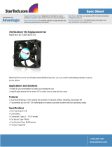 StarTech.com FAN7X25TX3 Datasheet
-
Hikvision DS-K2811 User manual
-
Dahua ASC3202B Quick start guide
-
-
 Digital Monitoring Products X1 SERIES ELEVATOR CONTROLLER Quick start guide
-
Dahua ASI7223X-A-T1 User manual
-
Honeywell PRO-2200 User manual
-
Security Camera King ACP-EL4 User manual

