5
is remote control has 14 channels. Before linking the remote, determine
which shade(s) you want on which channel. All shades linked to a remote will
also automatically be programmed to the “ALL” channel.
e 14 Channel remote may also be used to operate top down-bottom up cellular
shades. You can not mix a standard bottom up only shade and a TD/BU shade
on the same channel.
Remove plastic lm from the front of the remote. Remove screw from the back
of the remote and slide cover down and o. Do not replace cover until shades
have been linked and limits have been adjusted (if necessary). If battery is not
already installed in the remote follow the instructions on page 14.
1. Select the channel that you want to link the shades to, using the CHANNEL
selector button. e button will scroll through channels in ascending order only.
e remote will go back to channel 1 aer channel AL. See next page to disable
unused channels.
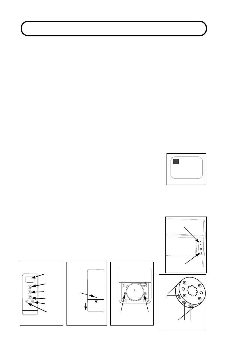
2. Make sure the On/O switch on the motor is set to “ON”
3. Conrm that the channel selected is set for bottom up only
shades by looking to see if a number 1, 2 or 3 shows in the le
of the display. If a number is shown, deactivate the Top Down/
Bottom Up function for that channel by pressing the RAIL
SELECTOR and DOWN buttons at the same time until the rail
selector number disappears from the le side of the screen.
4. Press the SETTING button on the motor until it beeps/jogs, then release. e
Important: Please read through this section completely before beginning.
01
1
On/O
Switch
Charging
Port
Setting
Button
ON OFF
Setting
(white button)
On/O Switch
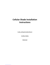
C
R
2
4
5
0
Channel
Display
Stop/Favorite
Down
Channel
Rail
Selector
Front
Conrm Limit
Back (cover on)
Up
Back (cover o)
Screw
Cover
slides
o
motor will make 4 fast beeps followed by 5 long beeps.
Press the CONFIRM button on the remote anytime
during the series of long beeps. It must be pressed
before the last long beep. e motor will beep and jog
conrming that the shade has been linked.
5. Repeat steps 1-4 to link remaining shades to the rest of
the channels.
STEP 3: LINK REMOTE