Page is loading ...

P/N: 4FQ020-010 v4.4, 06/02/2020
©2020 Vortech Engineering, Inc
All Rights Reserved, Intl. Corp. Secured
i
Ford 5.0L
Mustang GT
Supercharger System
Installation Instructions
2011-14 Model Year
50 State Smog Legal Per CARB EO #D-213-33
1650 Pacific Avenue, Channel Islands CA 93033-9901 • Phone: 805 247-0226
Fax: 805 247-0669 • www.vortechsuperchargers.com
ENGINEERING, INC
®

P/N: 4FQ020-010 v4.4, 06/02/2020
©2020 Vortech Engineering, Inc.
All Rights Reserved, Intl. Corp. Secured ii
FOREWORD
Take note of the following before proceeding:
1. Proper installation of this supercharger kit requires general automotive
mechanic knowledge and experience. Please browse through each step
of this instruction manual prior to beginning the installation to determine if
you should refer the job to a professional installer/technician. Please con-
tact your dealer or Vortech Engineering for possible installers in your
area.
2. This product was designed for use on stock (un-modified, OEM) vehicles. The PCM
(computer), engine, transmission, drive axle ratios and tire O.D. must be stock. If the
vehicle or engine has been modified in any way, check with Vortech prior to installation
and use of this product.
3. Use only premium grade fuel with a minimum of 91 octane (R+M/2).
4. Always listen for any sign of detonation (knocking/pinging) and discontinue hard use
(no boost) until problem is resolved.
5. Vortech is not responsible for any clutch, transmission, drive-line or engine damage.
Exclusions from Vortech warranty coverage considerations include, but not limited to:
1. Neglect, abuse, lack of maintenance, abnormal operation or improper installation.
2. Continued operation with an impaired vehicle or sub-system.
3. The combined use of Vortech components with other modifications such as, but not limit-
ed to, exhaust headers, aftermarket camshafts, nitrous oxide, third party PCM program-
ming or other such changes.
©2020 VORTECH ENGINEERING, INC
All rights reserved. No part of this publication may be reproduced, transmitted, transcribed, or translated
into another language in any form, by any means without written permission of Vortech Engineering, Inc.
This manual provides information on the installation, maintenance and service of the
Vortech supercharger kit expressly designed for this vehicle. All information, illustra-
tions and specifications contained herein are based on the latest product information
available at the time of this publication. Changes to the manual may be made at any time
without notice. Contact Vortech Engineering for any additional information regarding this kit
and any of these modifications at (805) 247-0226 7:00am-3:30pm PST.
STOP

P/N: 4FQ020-010 v4.4, 06/02/2020
©2020 Vortech Engineering, Inc
All Rights Reserved, Intl. Corp. Secured
iii
TABLE OF CONTENTS
FOREWORD ....................................................................ii
TABLE OF CONTENTS............................................................iii
IMPORTANT NOTES ..............................................................iv
TOOL & SUPPLY REQUIREMENTS..................................................v
PARTS LIST.....................................................................vi
1. BASIC COMPONENT REMOVAL ...............................................1
2. MISCELLANEOUS PREPARATION .............................................8
3. ENGINE COOLING SYSTEM MODIFICATION....................................10
4. SUPERCHARGER ASSEMBLY PREPARATION & INSTALLATION.................... 24
4.1 MOUNTING BRACKET ASSEMBLY DIAGRAM ................................28
4.2 BELT ROUTING DIAGRAM................................................29
5. PCV SYSTEM MODIFICATION................................................30
6. HORN ASSEMBLY RELOCATION .............................................32
7. CHARGE AIR COOLER (CAC) SYSTEM INSTALLATION ...........................34
7A. COOLER CORE INSTALLATION...........................................35
7B. DISCHARGE DUCT INSTALLATION, HOT SIDE...............................36
7C. DISCHARGE DUCT INSTALLATION, COLD SIDE. ............................37
8. BYPASS VALVE CONNECTION ...............................................40
9. FUEL INJECTOR REPLACEMENT .............................................42
10. MISCELLANEOUS REASSEMBLY .............................................44
11. AIR INLET ASSEMBLY INSTALLATION .........................................46
12. BUMPER COVER/FRONT FASCIA MODIFICATION AND REINSTALLATION ...........48
13. OIL FEED INSTALLATION (OIL-FED UNITS ONLY) ...............................53
14. OIL DRAIN INSTALLATION (OIL-FED UNITS ONLY)...............................55
15. REFLASH COMPUTER......................................................57
16. FINAL CHECK .............................................................58

P/N: 4FQ020-010 v4.4, 06/02/2020
©2020 Vortech Engineering, Inc.
All Rights Reserved, Intl. Corp. Secured iv
NOTICE
This product is protected by state common law, copyright and/or patent.
All legal rights therein are reserved. The design, layout, dimensions,
geometry, and engineering features shown in this product are the exclu-
sive property of Vortech Engineering, Inc. This product may not be cop-
ied or duplicated in whole or part, abstractly or fundamentally, intention-
ally or fortuitously, nor shall any design, dimension, or other information
be incorporated into any product or apparatus without prior written con-
sent of Vortech Engineering, Inc.

P/N: 4FQ020-010 v4.4, 06/02/2020
©2020 Vortech Engineering, Inc
All Rights Reserved, Intl. Corp. Secured
v
Before beginning this installation, please read through this entire instruction booklet and the Street
Supercharger System Owner’s Manual which includes the Limited Warranty Program, the Warranty
Registration form and return envelope.
Vortech supercharger systems are performance improving devices. In most cases, increases in
torque of 30-35% and horsepower between 35-45% can be expected with the boost levels specified
by Vortech Engineering. This product is intended for use on healthy, well maintained engines.
Installation on a worn-out or damaged engine is not recommended and may result in failure of the
engine as well as the supercharger. Vortech Engineering is not responsible for engine damage.
Installation on new vehicles will not harm or adversely affect the break-in period so long as factory
break-in procedures are followed.
For best performance and continued durability, please take note of the following key points:
1. Use only premium grade fuel 91 octane or higher (R+M/2).
2. The engine must have stock compression ratio.
3. If the engine has been modified in any way, check with Vortech prior to using this product.
4. Always listen for any sign of detonation (pinging) and discontinue hard use (no boost) until
problem is resolved.
5. Perform an oil and filter change upon completion of this installation and prior to test driving
your vehicle. Thereafter, always use a high grade SF rated engine oil or a high quality syn-
thetic, and change the oil and filter at least every 3,000 miles. Never attempt to extend the
oil change interval beyond 3,000 miles, regardless of oil manufacturer’s claims as potential
damage to the supercharger may result.
6. Before beginning installation, replace all spark plugs that are older than 1 year or 15,000
miles with original heat range plugs as specified by the manufacturer and reset timing to
factory specifications (follow the procedures indicated within the factory repair manual and/
or as indicated on the factory underhood emissions tag). Do not use platinum spark plugs
unless they are original equipment. Change spark plugs every 20,000 miles.
TOOL & SUPPLY REQUIREMENTS
• Factory repair manual
• 3/8" socket and drive set: SAE & metric
• 1/2" socket and drive set: SAE & metric
• Adjustable wrench
• Open end wrenches: metric
• TORX T-20 driver
• Utility knife
• Oil-Fed Kits: 3/8" NPT tap, center punch, 5/8" tapered punch, heavy grease,
8 quarts manufacturer-specified engine oil, oil filter, oil filter wrench
If it has been 35,000 miles or more since your vehicle’s last spark plug change, then you will
also need:
• Spark plug socket
• NEW spark plugs
2011-2014 Ford Mustang GT
Installation Instructions
Congratulations on selecting the best performing and best backed automotive
supercharger available today... the VORTECH® supercharger!

P/N: 4FQ020-010 v4.4, 06/02/2020
©2020 Vortech Engineering, Inc.
All Rights Reserved, Intl. Corp. Secured vi
®
PART NUMBER DESCRIPTION QTY. PART NUMBER DESCRIPTION QTY.
IMPORTANT: Before beginning installation, verify that all parts are included in the kit. Report any shortages or dam-
aged parts immediately.
PARTS LIST
008118 DECAL, VINYL, VORTECH 2
008130 LICENSE PLATE FRAME, VORTECH 1
008447 1 YR S/C WARRANTY PKG 1
009035 S/C LUBE, BOTTLED, 3-PACK 1
2F329-200 V3 S/C ASY,'11-'14 MSTG GT 1
4FQ020-010 INSTR MAN, '11-'14 MSTG GT 1
4FQ111-013 MNTG BRKT ASY, '11-'14 MSTG 5.0 1
2A017-875-27 SPACER, .875OD X .404ID X 1.895L 4
2A017-876-13 SPACER, .875OD X .328ID X 2.730L 2
2A017-876-14 SPACER, .875OD X .328ID X 2.058L 2
2A017-876-15 SPACER, .875OD X .328ID X 2.146L 1
2A017-876-16 SPACER, .875OD X .328ID X 1.928L 1
2A046-031 BELT, 6 RIB X 103.31 EFF. LENGTH 1
4FQ010-011 MNTG PLT, OUTER, 2011 MSTG 5.0 1
4FQ010-021 MNTG PLT, INNER, 2011 MSTG 5.0 1
4FQ017-021 SPCR, .875/1.25OD X .328ID X 1.782L 1
4FQ017-031 SPCR, .875ODX.404IDX.363L W/.66 PLT 4
4GF016-161 PULLEY, 3" IDLER, GROOVED, MOD 1
4PCS016-160 PULLEY, IDLER, SRT10 TRUCK 1
4TX016-150 IDLER, 2.75 DIA, SMOOTH, 7 RIB 2
7A375-126 3/8-16 X 1.25 HHCS, GR8, PLT 5
7A375-352 3/8-16 X 3.5" HX HD GR8 5
7C080-064 M8 X 1.25 X 65MM BHCS CL10.9 1
7C080-081 M8 X 1.25 X 80 HXHD CL10.9 1
7C080-101 M8-1.25 X 100 BHCS CL10.9 1
7C080-200 M8-1.25 X 200MM STUD, 35MM THREAD 2
7F008-021 NUT, M8 X 1.25, SERRATED FLG 2
7J312-000 5/16 FLAT WASHER-SAE 3
7K375-040 3/8 AN960 FLAT WASHR PLATED 9
7K375-050 3/8 WASHER, STAINLS, .030THK 1
2A017-875-28 SPACER, .875 OD X 2.730 LONG 1
4FQ112-010 AIR INLET ASY, '11-'14 MSTG 5.0 1
008358 DECAL, INLET, 2011 MSTG GT VORT 1
4FQ012-010 INLET DUCT, 2011 MSTG 5.0 CENT 1
5W001-039 1" HEAT SHRINK TUBING 3 IN
5W001-082 SLEEVE, FLEX BRAID, Ø.75" NOM. .75 FT
7J006-093 6MM WASHER, PLATED 2
7P375-039 3/8 NPT X 5/8" BARB 90° 1
7P375-106 PCV VALVE, FORD, 3/8" HOSE 2
7P625-004 5/8 TEE #28634 1
7P625-091 5/8 X 5/8 X 90° BARB ELBOW, PLASTIC 1
7P625-377 5/8" -3/8" RDCR BRB BLK PLASTIC 1
7PS375-100 SLEEVE, 3.75 X 1.0 3-PLY MATTE BLK 1
7PS400-225 BUMP SLEEVE, Ø4X2.25, BLACK 1
7PS400-351 SLEEVE,4.0 X 3.5 X 2.35L 1
7R002-056 #56 SAE TYPE F SS HOSE CLAMP 1
7R002-064 #64 SAE TYPE F SS HOSE CLAMP 3
7R004-002 STEPLESS CLAMP, 17.0-70 2
7R004-004 STEPLESS CLAMP, 1.0 OD HOSE 6
7U030-066 HOSE, 5/8" X 90°, 3" X 3" 1
7U032-016 3/8" EFI FUEL HSE HI-PSR 0.5 FT
7U033-000 5/8" PCV HOSE 2 FT
7U100-055 TIE WRAP, 7.5" NYLON 6
8A004-007-1 BLK OFF PLT, VORT, FORD SLT MAF 1
8H040-185 AIR FILTER, 2011 MSTG GT PANEL 1
4FQ114-010 CLNG SYS MOD ASY,'11-'14MSTG GT 1
4FE014-010 RADIATOR PIPE-STAINLESS 1
4FQ010-030 BRKT, CLNT RES, 2011 MSTG GT 1
4FQ010-040 BRKT B, CLNT RES, 2011 MSTG GT 1
4FQ010-050 BRKT, FAN MODULE, 2011 MSTG GT 1
4FQ010-060 AIR DAM, FAN SHROUD, 2011 MSTG GT 2
4FU014-060 WATER PIPE, Ø1.5 X 90, 07+ MUST GT 1
5W001-085 SLEEVE, FLEX BRAID, Ø1.5" NOM 1 FT
7A250-075 1/4-20 X .75 SHCS PLTD 1
7A250-125 1/4-20 X 1 1/4 SHCS ZINC PLTD 1
2A017-028 4.3 PLEUM SPACER A, .294 LONG 1
7F250-021 1/4-20 NYLOCK NUT ZINC PLATED 2
7A250-051 1/4-20 X .50 HHCS GR5 ZINC PLTD 4
7C006-038 6-32 X .375 BHCS, 18-8 SS 12
7F006-001 6-32 HEX NUT, NYLOCK GR5 12
7J006-093 6MM WASHER, PLATED 8
7P250-045 1/4 MALE NPT X 3/8 MALE BARB 1
7P312-050 5/16 UNION HOSEMENDER 2
7P375-050 3/8" HOSE UNION, BRASS 2
7P375-098 TEE, 3/8" INCH, PLASTIC 1
7R002-010 #10 SAE TYPE F SS HOSE CLAMP 2
7R002-028 #28 SAE TYPE F SS HOSE CLAMP 6
7R004-001 STEPLESS CLAMP, 15.7-70 4
7R004-002 STEPLESS CLAMP, 17.0-70 9
7R004-007 STEPLESS CLAMP, 28.6 X 7MM WIDE 1
7U030-056 3/8 PCV/VAC RUBBER HOSE 2.5 FT
7U031-016 5/16" PCV/VAC RUBBER HOSE 1 FT
7U133-050 1.5" X 90° HOSE, LONG LEG 1
8N055-080 TANK, RAD OVERFLOW, 05 MUST 1
7U038-000 3/4" HEATER HOSE 36"
4FQ212-030 DISCH ASY, '11-'14 MSTG 5.0 1
2A017-876-02 SPACER, .875 OD X 1.565 LONG 4
4FQ012-040 DISCH TUBE B, 2011 MSTG GT 1
4FQ012-050 DISCH TUBE C, 2011 MSTG GT 1
4FQ017-011 SPACER, TB, 1.25, 2011 MSTG GT 1
4FQ112-030 DISCH TUBE A, 2011 MSTG GT, BYPS 1
4GE012-030 DISCH TUBE A, 6.2 CAMARO SAT 2
4PGM012-010 ELBOW, REDUCER, 4X3.5, CAST 1
7C040-008 M4-.7X8MM SCHD SS 2
7C060-080 M6 X 1.00 X 80 SHCS CL 12.9 4
7C080-066 M8 X 1.25 X 65 HXHD CL10.9 4
7F008-021 NUT, M8 X 1.25, SERRATED FLG 4
7J006-093 6MM WASHER, PLATED 4
7J312-875 5/16" WASHER, CUSTOM 8
7P250-187 1/4 NPT FEM X 1/4" BARB 1
7P375-250 3/8"X3/8"X1/4"MALE BARB TEE 1
7P500-001 1/2" HOSE UNION 4
7P500-156 TEE, 1/2" RUN X 1/4 MALE NPT 1
7PS300-275 REDUCER, BLK Ø3.0-Ø2.75 1
7PS300-300 SLEEVE, BLACK, 3.00D X 3.00 3
7PS300-301 BUMP HOSE, 3.00D X 3.00L 1
7PS350-200 SLEEVE, BLACK 3.50"IDX2.0"LG 1
7PS350-304 SLEEVE, BLK, 3.5" X 3.0"L 1
7PS400-300 SLEEVE, BLK, 4.0" X 3.0"L 1
7PS400-301 REDUCER, HUMP, PROG 3.0 X 4.0 1
7R002-044 #44 SAE TYPE F SS HOSE CLAMP 1
7R002-048 #48 SAE TYPE F SS HOSE CLAMP 9
7R002-052 #52 SAE TYPE F SS HOSE CLAMP 4
7R002-056 #56 SAE TYPE F SS HOSE CLAMP 5
7R002-064 #64 SAE TYPE F SS HOSE CLAMP 3
7R004-687 STPLS CLAMP, 13/16", 1 EAR 8
7S300-003 RUBBER ELBOW 3" MODIFIED 2
7S350-120 ELBOW, Ø3.5", 120º, 2.5" C.L. 1
7S350-220 ASM, FLOW STRAIGHTENER, 3.5 OD 1
7U012-238 O-RING, 2-238, 3.484ID X .139 1
7U030-218 7/32 VAC HOSE, BUNA-N 48 IN
7U030-036 1/2" OIL DRAIN HOSE 3 FT
8A003-071 MAF, 3.8ID, 05 MSTG GT 1
8H040-175 FILTER, 1.75"ID, RACE BYPS 1
5A003-070 ECU REFLASH TL, '11-'14 MSTG GT 1
8D204-054 RACE BYPASS VALVE-BLACK/SAT 1
8F160-046 FUEL INJ ASY, '11-'14 MSTG GT 1
4FQ017-041 SPCR, FUEL RAIL, EV14, 2011 MSTG GT 4
8F060-046 FUEL INJ, 47LB EV14 8
7C060-091 M6 X 1.0 X 90MM SHCS PLT GR12.9 4
7J250-001 1/4 WASHER, SAE, PLATED 4
8PN101-050 WELDED CAC CORE ASY 1
2011-14 Ford Mustang GT, H.O.
Part No. 4FQ218-020L
ENGINEERING, INC

P/N: 4FQ020-010 v4.4, 06/02/2020
©2020 Vortech Engineering, Inc
All Rights Reserved, Intl. Corp. Secured
vii
®
PART NUMBER DESCRIPTION QTY. PART NUMBER DESCRIPTION QTY.
IMPORTANT: Before beginning installation, verify that all parts are included in the kit. Report any shortages or dam-
aged parts immediately.
PARTS LIST
2011-14 Ford Mustang GT, H.O. Tuner Kit
Part No. 4FQ218-120L
008118 DECAL, VINYL, VORTECH 2
008130 LICENSE PLATE FRAME, VORTECH 1
008447 1 YR S/C WARRANTY PKG 1
009035 S/C LUBE, BOTTLED, 3-PACK 1
2F329-200 V3 S/C ASY,'11-'14 MSTG GT 1
4FQ020-010 INSTR MAN, '11-'14 MSTG GT 1
4FQ111-013 MNTG BRKT ASY, '11-'14 MSTG 5.0 1
2A017-875-27 SPACER, .875OD X .404ID X 1.895L 4
2A017-876-13 SPACER, .875OD X .328ID X 2.730L 2
2A017-876-14 SPACER, .875OD X .328ID X 2.058L 2
2A017-876-15 SPACER, .875OD X .328ID X 2.146L 1
2A017-876-16 SPACER, .875OD X .328ID X 1.928L 1
2A046-031 BELT, 6 RIB X 103.31 EFF. LENGTH 1
4FQ010-011 MNTG PLT, OUTER, 2011 MSTG 5.0 1
4FQ010-021 MNTG PLT, INNER, 2011 MSTG 5.0 1
4FQ017-021 SPCR, .875/1.25OD X .328ID X 1.782L 1
4FQ017-031 SPCR, .875ODX.404IDX.363L W/.66 PLT 4
4GF016-161 PULLEY, 3" IDLER, GROOVED, MOD 1
4PCS016-160 PULLEY, IDLER, SRT10 TRUCK 1
4TX016-150 IDLER, 2.75 DIA, SMOOTH, 7 RIB 2
7A375-126 3/8-16 X 1.25 HHCS, GR8, PLT 5
7A375-352 3/8-16 X 3.5" HX HD GR8 5
7C080-064 M8 X 1.25 X 65MM BHCS CL10.9 1
7C080-081 M8 X 1.25 X 80 HXHD CL10.9 1
7C080-101 M8-1.25 X 100 BHCS CL10.9 1
7C080-200 M8-1.25 X 200MM STUD, 35MM THREAD 2
7F008-021 NUT, M8 X 1.25, SERRATED FLG 2
7J312-000 5/16 FLAT WASHER-SAE 3
7K375-040 3/8 AN960 FLAT WASHR PLATED 9
7K375-050 3/8 WASHER, STAINLS, .030THK 1
2A017-875-28 SPACER, .875 OD X 2.730 LONG 1
4FQ112-010 AIR INLET ASY, '11-'14 MSTG 5.0 1
008358 DECAL, INLET, 2011 MSTG GT VORT 1
4FQ012-010 INLET DUCT, 2011 MSTG 5.0 CENT 1
5W001-039 1" HEAT SHRINK TUBING 3 IN
5W001-082 SLEEVE, FLEX BRAID, Ø.75" NOM. .75 FT
7J006-093 6MM WASHER, PLATED 2
7P375-039 3/8 NPT X 5/8" BARB 90° 1
7P375-106 PCV VALVE, FORD, 3/8" HOSE 2
7P625-004 5/8 TEE #28634 1
7P625-091 5/8 X 5/8 X 90° BARB ELBOW, PLASTIC 1
7P625-377 5/8" -3/8" RDCR BRB BLK PLASTIC 1
7PS375-100 SLEEVE, 3.75 X 1.0 3-PLY MATTE BLK 1
7PS400-225 BUMP SLEEVE, Ø4X2.25, BLACK 1
7PS400-351 SLEEVE,4.0 X 3.5 X 2.35L 1
7R002-056 #56 SAE TYPE F SS HOSE CLAMP 1
7R002-064 #64 SAE TYPE F SS HOSE CLAMP 3
7R004-002 STEPLESS CLAMP, 17.0-70 2
7R004-004 STEPLESS CLAMP, 1.0 OD HOSE 6
7U030-066 HOSE, 5/8" X 90°, 3" X 3" 1
7U032-016 3/8" EFI FUEL HSE HI-PSR 0.5 FT
7U033-000 5/8" PCV HOSE 2 FT
7U100-055 TIE WRAP, 7.5" NYLON 6
8A004-007-1 BLK OFF PLT, VORT, FORD SLT MAF 1
8H040-185 AIR FILTER, 2011 MSTG GT PANEL 1
4FQ114-010 CLNG SYS MOD ASY,'11-'14MSTG GT 1
4FE014-010 RADIATOR PIPE-STAINLESS 1
4FQ010-030 BRKT, CLNT RES, 2011 MSTG GT 1
4FQ010-040 BRKT B, CLNT RES, 2011 MSTG GT 1
4FQ010-050 BRKT, FAN MODULE, 2011 MSTG GT 1
4FQ010-060 AIR DAM, FAN SHROUD, 2011 MSTG GT 2
4FU014-060 WATER PIPE, Ø1.5 X 90, 07+ MUST GT 1
5W001-085 SLEEVE, FLEX BRAID, Ø1.5" NOM 1 FT
7A250-075 1/4-20 X .75 SHCS PLTD 1
7A250-125 1/4-20 X 1 1/4 SHCS ZINC PLTD 1
2A017-028 4.3 PLEUM SPACER A, .294 LONG 1
7F250-021 1/4-20 NYLOCK NUT ZINC PLATED 2
7A250-051 1/4-20 X .50 HHCS GR5 ZINC PLTD 4
7C006-038 6-32 X .375 BHCS, 18-8 SS 12
7F006-001 6-32 HEX NUT, NYLOCK GR5 12
7J006-093 6MM WASHER, PLATED 8
7P250-045 1/4 MALE NPT X 3/8 MALE BARB 1
7P312-050 5/16 UNION HOSEMENDER 2
7P375-050 3/8" HOSE UNION, BRASS 2
7P375-098 TEE, 3/8" INCH, PLASTIC 1
7R002-010 #10 SAE TYPE F SS HOSE CLAMP 2
7R002-028 #28 SAE TYPE F SS HOSE CLAMP 6
7R004-001 STEPLESS CLAMP, 15.7-70 4
7R004-002 STEPLESS CLAMP, 17.0-70 9
7R004-007 STEPLESS CLAMP, 28.6 X 7MM WIDE 1
7U030-056 3/8 PCV/VAC RUBBER HOSE 2.5 FT
7U031-016 5/16" PCV/VAC RUBBER HOSE 1 FT
7U133-050 1.5" X 90° HOSE, LONG LEG 1
8N055-080 TANK, RAD OVERFLOW, 05 MUST 1
7U038-000 3/4" HEATER HOSE 36"
4FQ212-030 DISCH ASY, '11-'14 MSTG 5.0 1
2A017-876-02 SPACER, .875 OD X 1.565 LONG 4
4FQ012-040 DISCH TUBE B, 2011 MSTG GT 1
4FQ012-050 DISCH TUBE C, 2011 MSTG GT 1
4FQ017-011 SPACER, TB, 1.25, 2011 MSTG GT 1
4FQ112-030 DISCH TUBE A, 2011 MSTG GT, BYPS 1
4GE012-030 DISCH TUBE A, 6.2 CAMARO SAT 2
4PGM012-010 ELBOW, REDUCER, 4X3.5, CAST 1
7C040-008 M4-.7X8MM SCHD SS 2
7C060-080 M6 X 1.00 X 80 SHCS CL 12.9 4
7C080-066 M8 X 1.25 X 65 HXHD CL10.9 4
7F008-021 NUT, M8 X 1.25, SERRATED FLG 4
7J006-093 6MM WASHER, PLATED 4
7J312-875 5/16" WASHER, CUSTOM 8
7P250-187 1/4 NPT FEM X 1/4" BARB 1
7P375-250 3/8"X3/8"X1/4"MALE BARB TEE 1
7P500-001 1/2" HOSE UNION 4
7P500-156 TEE, 1/2" RUN X 1/4 MALE NPT 1
7PS300-275 REDUCER, BLK Ø3.0-Ø2.75 1
7PS300-300 SLEEVE, BLACK, 3.00D X 3.00 3
7PS300-301 BUMP HOSE, 3.00D X 3.00L 1
7PS350-200 SLEEVE, BLACK 3.50"IDX2.0"LG 1
7PS350-304 SLEEVE, BLK, 3.5" X 3.0"L 1
7PS400-300 SLEEVE, BLK, 4.0" X 3.0"L 1
7PS400-301 REDUCER, HUMP, PROG 3.0 X 4.0 1
7R002-044 #44 SAE TYPE F SS HOSE CLAMP 1
7R002-048 #48 SAE TYPE F SS HOSE CLAMP 9
7R002-052 #52 SAE TYPE F SS HOSE CLAMP 4
7R002-056 #56 SAE TYPE F SS HOSE CLAMP 5
7R002-064 #64 SAE TYPE F SS HOSE CLAMP 3
7R004-687 STPLS CLAMP, 13/16", 1 EAR 8
7S300-003 RUBBER ELBOW 3" MODIFIED 2
7S350-120 ELBOW, Ø3.5", 120º, 2.5" C.L. 1
7S350-220 ASM, FLOW STRAIGHTENER, 3.5 OD 1
7U012-238 O-RING, 2-238, 3.484ID X .139 1
7U030-218 7/32 VAC HOSE, BUNA-N 48 IN
7U030-036 1/2" OIL DRAIN HOSE 3 FT
8A003-071 MAF, 3.8ID, 05 MSTG GT 1
8H040-175 FILTER, 1.75"ID, RACE BYPS 1
8D204-054 RACE BYPASS VALVE-BLACK/SAT 1
8PN101-050 WELDED CAC CORE ASY 1
ENGINEERING, INC

P/N: 4FQ020-010 v4.4, 06/02/2020
©2020 Vortech Engineering, Inc.
All Rights Reserved, Intl. Corp. Secured viii
(This page was intentionally left blank)

P/N: 4FQ020-010 v4.4, 06/02/2020
©2020 Vortech Engineering, Inc
All Rights Reserved, Intl. Corp. Secured
1
A. Locate the Ambient Air Temperature sensor in the
lower grille opening on the driver side of the front
bumper cover. Free the plastic clip from its
attachment point. (See Fig. 1A)
B. Remove four (4) 7mm-headed fasteners under the
front bumper cover in front of the lip. (See Fig.
1B)
C. Remove five (5) 7mm-headed fasteners securing
the black plastic front undertray. Remove the
undertray by moving it back and down and set it
aside for later reinstallation. (See Fig. 1C)
D. Remove two (2) 7mm-headed fasteners from the
front edge of each front wheel well (four screws
total), which secure the splash shield to the front
fascia. (See Fig. 1D)
1. BASIC COMPONENT REMOVAL
Fig. 1A: Ambient Air Temp Sensor
Fig. 1B: Front Bumper Cover Lip
Fig. 1D: Splash Shields Fig. 1C: Front Undertray
NOTE: Retain all fasteners & note
the original location of each for
future re-use.

P/N: 4FQ020-010 v4.4, 06/02/2020
©2020 Vortech Engineering, Inc.
All Rights Reserved, Intl. Corp. Secured 2
1. BASIC COMPONENT REMOVAL, cont’d
Fig. 1E: Plastic Cover Pins
E. Remove eight (8) plastic pins securing the black
plastic cover above the grille and radiator. Pop
the center section of each pin upward and then
the larger part of the pin will loosen. Remove the
cover and set aside for later reinstallation. (See
Fig. 1E)
F. '11-'12 Mustang: Remove two (2) 8mm-headed
fasteners from the body-color tabs on the stop
edge of the grille between the headlights and driv-
ing lights. (See Fig. 1F)
G. '13-'14 Mustang: Remove the four (4) 8mm-head-
ed fasteners from the top of the bumper. (See Fig.
1G)
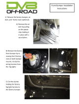
H. Separate the ends of the front fascia from the
fenders by pulling straight outward. The fascia
will snap free from three (3) clips per side. (See
Fig. 1H)
I. Reach behind the front fascia and unplug the
parking lights (1 per side). Also unplug the driving
lights.
Fig. 1F: Top Edge Fasteners
('11-'12 Mustang)
Fig. 1H: Front Fascia Tabs Fig. 1G: Top Bumper Cover Fasteners
('13-'14 Mustang)

P/N: 4FQ020-010 v4.4, 06/02/2020
©2020 Vortech Engineering, Inc
All Rights Reserved, Intl. Corp. Secured
3
Fig. 1J: Front Fascia Removal
1. BASIC COMPONENT REMOVAL, cont’d
Fig. 1K: Front Bumper Cushion Pins
Fig. 1L: Radiator Side Shroud, Passenger
('11-'12 Mustang)
Fig. 1M: Radiator Side Shroud, Driver
('11-'12 Mustang)
J. '11-'12 Mustang: Lift the front fascia from the
locating tabs adjacent to each headlight (by the
previously-removed 8mm-headed fastener loca-
tions). Pull the fascia forward and away from the
car and set it aside for later modification and rein-
stallation. (See Fig. 1J)
K. '13-'14 Mustang: Slide the front fascia forward,
removing it from the bumper cover support. Set
the front fascia aside for later reinstallation.
L. Remove the four (4) plastic pins securing the
Styrofoam front bumper cushion and set the pins
and cushion aside for later reinstallation. (See Fig.
1K)
M. '11-'12 Mustang: remove the two (2) plastic pins
securing the passenger side radiator side shroud.
Remove the shroud and set it aside. (See Fig. 1L)
N. '11-'12 Mustang: Remove the plastic pin securing
the Ambient Air Temperature sensor hasness from
the bottom of the driver side radiator side shroud.
Remove the two (2) plastic pins securing the
shroud itself, snap the shroud free from the airbox
snorkel, and set it aside. (See Fig. 1M)

P/N: 4FQ020-010 v4.4, 06/02/2020
©2020 Vortech Engineering, Inc.
All Rights Reserved, Intl. Corp. Secured 4
Fig. 1Q: Engine Cover
Fig. 1O: Lower Fastener
('13-'14 Mustang. Passenger Side Shown,
Drivers Side Similar)
Fig. 1P: Lower Mounting Block.
('13-'14 Mustang. Passenger Side Shown,
Drivers Side Similar)
1. BASIC COMPONENT REMOVAL, cont’d
Fig. 1N: Bumper Cover Support Fasteners
('13-'14 Mustang)
O. '13-'14 Mustang: Remove the two (2) 8mm-head-
ed fasteners from the top of the plastic bumper
cover support, between the headlights. (See Fig.
1N)
P. '13-'14 Mustang: Locate the two (2) 8mm-headed
fasteners on the bottom of the bumper cover sup-
port (near the radiator side shrouds) & remove
them. (See Fig. 1O)
Q. '13-'14 Mustang: Remove the 8mm-headed fas-
tener holding the lower mounting block of the
bumper cover support to the radiator support (the
radiator side shroud is trapped between this block
& the radiator support). The head of the fastener
is located underneath each headlight. Complete
this step for both driver & passenger side. (See
Fig. 1P)
R. If equipped, remove the strut tower brace by
removing the four (4) 13mm nuts (2 per side). Pop
the engine cover free from its four (4) rubber
grommet mounts & set it aside. (See Fig. 1Q)

P/N: 4FQ020-010 v4.4, 06/02/2020
©2020 Vortech Engineering, Inc
All Rights Reserved, Intl. Corp. Secured
5
1. BASIC COMPONENT REMOVAL, cont’d
Fig. 1R-1: Sound Tube, Front
S. Release the clamp securing the corrugated sound
tube to the OEM air inlet duct. Cut the clamp
securing the tube to the diaphragm housing at the
other end. Disconnect both ends of the tube,
snap its mounts free from the airbox and strut
tower, and set the tube aside. It will not be
reused. (See Figs. 1R-1 & 1R-2)
T. Remove the driver side and passenger side PCV/
breather hoses by disconnecting the quick-release
fittings at each end. Set them aside for later mod-
ification and reinstallation. (See Fig. 1S)
Automatic Transmission Only: Disconnect the
small quick-release fitting from the OEM air inlet
duct near the sound tube and breather hose con-
nections.
U. Loosen the hose clamps at each end of the OEM
air inlet duct – one at the throttle body and one at
the airbox. Remove the duct and set it aside. It
will not be reused. (See Fig. 1T)
V. Remove the 10mm-headed fastener securing the
OEM airbox to the driver side inner fender.
Remove the airbox and set it aside for later rein-
stallation.
W. Remove the 10mm nut securing the OEM cold air
snorkel to the fan shroud mounting stud screw
and remove the snorkel. Set it aside for later rein-
stallation.
Fig. 1R-2: Sound Tube, Rear
Fig. 1S: PCV HosesFig. 1T: OEM Air Inlet Duct

P/N: 4FQ020-010 v4.4, 06/02/2020
©2020 Vortech Engineering, Inc.
All Rights Reserved, Intl. Corp. Secured 6
1. BASIC COMPONENT REMOVAL, cont’d
Fig. 1W: Radiator Drain Valve
X. Remove the pressure cap from the engine coolant
reservoir near the passenger side front of the
engine compartment. Locate the engine coolant
drain valve at the bottom passenger side corner of
the radiator. Open the valve with the hex fitting
and drain the coolant into a clean container for
later reuse. Drain enough to empty the reservoir
and below the level of the upper radiator hose.
(See Fig. 1W)
Y. Unclamp and disconnect the two small hoses from
the upper portion of the coolant reservoir. (See
Fig. 1X)
Z. Unclamp and disconnect the larger hose from the
bottom of the coolant reservoir. Be prepared to
catch any spillage.
AA. Remove the two (2) 10mm-headed fasteners
securing the coolant reservoir. Remove the reser-
voir and set it aside. It will not be reused. (See
Fig. 1Z)
AB. Release the upper radiator hose clamp connec-
tion to the radiator. Release the quick release
upper radiator hose connection to the thermostat
housing by pulling the spring clip back and sliding
the hose fitting off. Remove the upper radiator
hose and set it aside for later modification and
reuse. (See Fig. AA)
Fig. 1X: Small Coolant Hoses
Fig. 1Z: Coolant ReservoirFig. AA: Upper Radiator Hose

P/N: 4FQ020-010 v4.4, 06/02/2020
©2020 Vortech Engineering, Inc
All Rights Reserved, Intl. Corp. Secured
7
1. BASIC COMPONENT REMOVAL, cont’d
Fig. 1AD: Belt Tensioner
AC. Unplug the electrical connector from the fan
assembly directly under the radiator inlet.
AD. Remove the two (2) 10mm-headed fasteners
securing the radiator fan assembly to the radiator
(one per side, near the top of the shroud). Lift
the fan assembly upward off of the tab/slot con-
nection on either side and remove. Set it aside
for later modification and reinstallation.
AE. Use a 15mm wrench to rotate the belt tensioner
counter-clockwise to release tension from the
outer 6-rib accessory drive belt. Remove the belt
and set it aside as it will not be reused. (See Fig.
1AD)
AF. Remove the two (2) TORX T-20 fasteners secur-
ing the MAF insert into the OEM airbox. Remove
the MAF insert and set aside for later use. (See
Fig. 1AE)
AG. Unplug the electrical connector from the throttle
body by sliding the red clip outward and depress-
ing the tab. (See Fig. 1AF)
AH. Remove the four (4) 10mm-headed screws secur-
ing the throttle body to the intake manifold. These
fasteners will not be reused. Remove the throttle
body and set it aside for later reinstallation, ensur-
ing that the sealing gasket remains in the intake
manifold. (See Fig. 1AG)
Fig. 1AG: Throttle Body Fasteners
Fig. 1AE: MAF Insert
(shown with OEM airbox removed)
Fig. 1AF: Throttle Body Connector

P/N: 4FQ020-010 v4.4, 06/02/2020
©2020 Vortech Engineering, Inc.
All Rights Reserved, Intl. Corp. Secured 8
2. MISCELLANEOUS PREPARATION
Fig. 2A: Wiring Harness
A. Free the large wiring harness from the two (2)
mounting locations on the engine front cover for-
ward of the passenger side cylinder head. Use
extra care when disengaging the lower clip from
the threaded hole in the engine cover as this
threaded hole will be used in a later step. If part
of the clip breaks off in the threaded hole, careful-
ly extract it without damaging the threads. Route
the harness higher up along the passenger side
valve cover. (See Fig. 2A)
B. Carefully cut the OEM plastic hose clamp on the
hose running between the “Y” on the thermostat
housing and the engine water neck. Take extra
care not to damage the hose. (See Fig. 2B)
C. Re-clamp the hose in the previous step with the
included #28 worm gear clamp. Orient the clamp
so the screw mechanism is toward the driver side,
away from the throttle body mounting location.
(See Fig. 2C)
D. Free the large electrical connector near the radia-
tor inlet from its mounting location. Leaving it
connected, relocate it forward of the power distri-
bution box/ECU and secure with zip ties. (See
Fig. 2D)
E. Remove the coil covers from the cylinder heads.
Remove the ignition coils and spark plugs. Re-gap
the spark plugs to .032", re-install and torque to 9
ft-lbs. Reinstall the coils and coil covers. Fig. 2B: OEM Plastic Hose Clamp
Fig. 2C: #28 Hose Clamp Orientation
Fig. 2D: Electrical Connector

P/N: 4FQ020-010 v4.4, 06/02/2020
©2020 Vortech Engineering, Inc
All Rights Reserved, Intl. Corp. Secured
9
2. MISCELLANEOUS PREPARATION, cont'd
F. Automatic Transmission Only: Locate the two
transmission cooler hoses and hard lines on the
passenger side of the engine compartment. (See
Fig. 2F)
G. Automatic Transmission Only: Clamp the rub-
ber hoses at either end of the hard line sections to
minimize fluid loss. Cut the forward rubber hose
segments as close to the hard lines as possible,
so the cut ends point directly rearward. (See Fig.
2G)
H. Automatic Transmission Only: Clamp and cut
the rubber hoses at the other end of the hard
lines. Cut these further back at a location that will
allow the extended hoses to travel along the pas-
senger side frame rail.
I. Automatic Transmission Only: Use the included
black nylon 1/2" hose unions, 1/2" braided hose,
and 13/16" stepless clamps to join the cut OEM
rubber hose ends together. Route the hoses
along the passenger side frame rail, leaving suffi-
cient slack to allow for engine movement. (See
Figs. 2H-1, 2H-2)
Fig. 2F: OEM A/T Cooler Hoses & Hard Lines
Fig. 2G: Clamping and Cutting A/T Hoses
Fig. 2H-1: Joining A/T HosesFig. 2H-2: Completed A/T Hose Modification
NOTE: Take care to connect each
hose to the appropriate/matching
other end.

P/N: 4FQ020-010 v4.4, 06/02/2020
©2020 Vortech Engineering, Inc.
All Rights Reserved, Intl. Corp. Secured 10
3. ENGINE COOLING SYSTEM MODIFICATION
Fig. 3B: Upper Radiator Hose
A. Locate the previously-removed OEM upper radia-
tor hose. Pull back the braided abrasion sleeve
from the quick-release end of the hose, well clear
of the 90° hose bend.
B. Cleanly and squarely cut the upper radiator hose
approximately 2” back from the quick-release leg
as shown. (See Fig. 3B)
C. Insert the short end of the included Ø1.5” x 90°
steel pipe into the long end of the cut radiator
hose and orient as shown, securing with an
included #28 worm gear clamp. (See Fig. 3C)
D. Reattach the long portion of the OEM radiator
hose to the radiator same as before, but clocked
so the long leg is routed downward along the pas-
senger side of the engine. The exposed leg of
the 90° steel pipe should point directly to the driv-
er side. Secure the hose to the radiator with the
OEM clamp. (See Fig. 3D)
E. Cut away the plastic hose clamp on the quick-
release end of the cut radiator hose in a similar
manner as previously done with the short upper
radiator hose, taking care not to damage the
hose. (See Fig. 3E)
Fig. 3C: Radiator Pipe
Fig. 3D: Upper Radiator HoseFig. 3E: OEM Plastic Hose Clamp

P/N: 4FQ020-010 v4.4, 06/02/2020
©2020 Vortech Engineering, Inc
All Rights Reserved, Intl. Corp. Secured
11
3. ENGINE COOLING SYSTEM MODIFICATION, cont'd
Fig. 3F: Upper Radiator Hose
F. Carefully remove the cut hose from the quick-
release fitting. (See Fig. 3F)
G. Cut the hose at the approximate middle of the 90°
bend, creating a 45° bend. Reinstall it onto the
quick-release fitting, orient it as shown, and
secure with an included #28 worm gear clamp.
Insert the Ø1.5” stainless steel hose union into the
open end and secure with an included #28 worm
gear clamp. (See Fig. 3G-1) When properly
assembled with the quick-release temporarily
reconnected, the stainless steel union should
point slightly toward the passenger side from
straight down. (See Fig. 3G-2)
H. Locate the included Ø1.5” x 90° rubber hose.
Slide the shorter leg over the exposed end of the
stainless steel hose union and orient as shown,
completely covering the union. When properly
assembled with the quick-release temporarily
reconnected, the long leg of this hose should
point straight toward the passenger side (See Fig.
3H). Slide a segment of the included Ø1.5” black
flex braid abrasion sleeve around each straight
portion of the hose as shown.
Fig. 3G-1: Upper Radiator Hose
Fig. 3G-2: Upper Radiator HoseFig. 3H: Upper Radiator Hose

P/N: 4FQ020-010 v4.4, 06/02/2020
©2020 Vortech Engineering, Inc.
All Rights Reserved, Intl. Corp. Secured 12
3. ENGINE COOLING SYSTEM MODIFICATION, cont'd
Fig. 3I: Modified Upper Radiator Hose
I. Cut approximately 2.75” from the long leg of the
Ø1.5” x 90° rubber hose to mate up with the
exposed long leg of the 90° steel pipe. Secure
with an included #28 worm gear clamp.
J. Install the new upper radiator hose assembly,
ensuring the quick-release mechanism securely
snaps into place. Check all connections, and
ensure that the hose is routed away from moving
parts and sharp edges. (See Fig. 3I)
K. Remove the two (2) innermost 13mm hex nuts on
the top of the passenger side strut tower. These
nuts may have already been removed if the car is
equipped with a strut tower brace. (See Fig. 3K)
L. Remove the 10mm hex nut from the stud on the
power distribution box directly across from the oil
filler cap. (See Fig. 3L) If equipped, first remove
the upper 10mm hex nut and OEM ground wire.
All of these will be reinstalled in a later step.
M. Gently bend the A/C service port toward the pas-
senger side between the power distribution box
and the strut tower. (See Fig. 3M)
Fig. 3K: Passenger Side Strut Tower
Fig. 3L: 10mm Hex NutFig. 3M: A/C Service Port
/