Page is loading ...

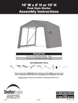
Description Part # Qty.
Cover Rail Plain Ends 45 3/4"L 10110 10
Cross Rail Plain Ends 48 1/2”L 2031 3
Cross Rail Swedged 50 1/2”L 2030 12
Middle Upright Tube 56”L 10203 8
Wind Brace (Flat Ends) 55 1/2”L 10205 2
Bent Corner Leg 10226 4
Side Bend Plain 80”L 10225 6
Side Bend Swedged 80”L 10224 6
Extension 27”L 10223 12
All-Weather Cover 10277 1
800196 1
Ratchet - 1" 10040 4
ATTENTION:
BOLTS ARE NOT NEED-
ED OR
INCLUDED FOR EVERY
CONNECTION BUT MAY
BE
PURCHASED BY CALL-
ING THE
NUMBER BELOW
FOR MISSING OR
REPLACEMENT PARTS
OR
QUESTIONS
PLEASE CONTACT
CUSTOMER SERVICE:
1-800-524-9970
12x24x10 Run-In Shed #51451
Please read instructions completely before assembly
150 Callender Rd.
Watertown, CT. 06795
PAGE 1
Manufactured Under
U.S. Patents
D415,571 D409,310
D430,306 D414,564
Other Patents Pending
Boot

Description Part # Qty.
4-Way Cover Rail Clamp 10111 16
3-Way Cover Rail Clamp 10112 8
1/4” x 3” Bolt (For Cross Rail) 10210 14
1/4” x 3” Round Head Bolt (Top) 00669 4
1/4” x 2” Bolts 10114 4
1/4” x 1 5/8” Bolts (for Clamps) 00671 20
1/4” Nuts 01010 48
Bolt Cap’s 10150 16
PAGE 2
ATTENTION:
BOLTS ARE NOT
NEEDED OR
INCLUDED FOR EVERY
CONNECTION BUT
MAY BE
PURCHASED BY CALL-
ING THE
NUMBER BELOW
FOR MISSING OR
REPLACEMENT PARTS
OR
QUESTIONS
PLEASE CONTACT
CUSTOMER SERVICE:
1
1-800-524-9970
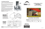
Frame Assembly Overview

2”
Bolts
PAGE 3
Frame Assembly
•Step 1
Fit together an end rib using the following parts (1) #10224 Bent
Tube Swedged, (1) #10225 Bent Tube Plain, (2) #10223 Extension
and (2) #10226 Bent Corner Leg. Using (4) #10114 1/4” x 2” L
Carriage Bolts and (4) #1010 1/4” Nuts securely fasten the joints of
the Corner legs to the extensions and the extensions to the bends.
Lay this rib on the ground at the rear of your shelters designated
location.
•Step 2
Fit together a middle rib using the following parts (1) #10224 Bent
Tube Swedged, (1) #10225 Bent Tube Plain (2) #10223 Extension
and (2) #10203 Middle Upright Tube. Lay this rib on the ground near
the first end rib.
Note 1: The joint between the upright tubes and the
extension will not be bolted, only the joint of the exten-
sion to the bend requires a bolt.
•Step 3
Stand the rear end rib vertically and lean against a permanent struc-
ture such as a tree or fence. Attach the plain end of a #2030 Cross
Rail Swedged to the first rib using a 1/4” x 3” L Carriage Bolt and
1/4” Nut on the INSIDE of the bow, on each side bend just above the
joint of the side bend to the extension. Next, attach a #10205 Wind
Brace using a 1/4” x 2”L Carriage Bolt and Nut to each corner
upright tube. Place (2) #10112 3-Way Connectors around the bent
corner leg, insert the end of a #10110 Cover Rail Tube into the 3-
Way connector and fasten these with a 1/4” x 1 5/8” Bolt and Nut.
Slide the connector until it is 5” up from the ground and loosely tight-
en. Repeat at the other bent corner leg.
•Step 4
Attach a #10111 4-Way Connector to the end of the 2 cover rail
tubes and loosely fasten with a 1/4” x 1 3/4” Bolt and 1/4” Nut.
Insert another cover rail tube into each 4-Way connector and loosely
fasten with a 1/4” x 1 3/4” Bolt and Nut. Place the plain end of
another #2030 Cross Rail Swedged over the swedged end of those
already attached and lean them down. Stand the middle rib vertical-
ly and insert the bottom of each upright tube into the 4-way connec-
tor. Raise the cross rail assemblies up and bolt them to the middle
rib with a 1/4” x 3” L Carriage Bolt and Nut. Attach the lower end of
the wind braces to the middle rib with 1/4” x 2” L Carriage Bolt and
Nut. Slide the 4-Way connectors until they are 5” up from the
ground and tighten loosely.
•Step 5
Repeat Step 4 for the remaining middle ribs and finish with the final
end rib.
4
No
Bolts
1
2
3
2”
Bolts

PAGE 4
INSTALLING TOP RAIL
Install top cross rail assembly starting with (1)
#2031 Plain Cross Rail Tube UNDER the last bow
and on TOP of the all the middle bows. End with
the plain end of the Cross Rail Tapered End
UNDER the the front bow.
NOTE: Use the Special Round Head 1/4” x 3”
Bolts for securing the top rail to the Middle
Ribs only !
Slit's
Slit's
Wrap to inside
End Panel Installation
•Step 1
Hold the end panel from the top center with the white
inner surface facing the inside of the shelter. (If your
shelter is white the inner surface has the visible welded
seams.) Remove the nut holding the top cross rail to
the rib and carefully pull down the cross rail to free it
from the bolt. Wrap the end panel material up over the
rib and down towards the ground. Place the free end of
the cross rail through the slit in the panel and re-attach
the bolt and nut. You may now tighten the nut firmly.
Your end panel will now hang from the top of the bow.
Be sure to keep the zippers completely closed while
installing a door panel.
•Step 2
Repeat the process of removing the cross rail, placing
the rail through the slit and securing the bolts at both
upper side rails one side at a time. The wind braces also
need to be disconnected from their upper bolt and
placed through slits. Check that the material is not
trapped between cross rail or wind brace and the rib.
The rope welded into the pocket should now be on the
inside of the shelter and follow the shape of the rib.
•Step 3
Locate where the rope exits the pocket, grasp the rope
on one side of the shelter and pull downwards taking out
some of the slack in the rope; be sure that you do not
pull the rope up into the pocket on the other side. Tie
the rope around the bent leg firmly between the hole
and the end of the leg . Repeat the process of taking
out slack and tying the rope on the other side making
sure to make it as tight as possible. When complete the
bottom edge of the end panel should be approximately
1” up off of the surface, there should be no wrinkles in
the fabric and it should be taught across the end of the
frame.
Install the Top Rail
OVER all Middle Ribs
UNDER First & Last Ribs

SECURING YOUR COVER
Pull the cover over the frame. The welded in webbing should be at the front and back of the building. Also note that the pcoket with
cutouts, running along the sides of the cover should be on the inside and near the ground. Insert the "S" hook from the ratchets into the
hole in the leg of the frame. Next insert the webbing into the spindle of the ratchet and tighten rathchet until the webbing overlaps itself,
do not tighten all the way yet. Check to be sure the cover still has an even overhang on the front and rear, adjust as necessary. Once
the cover is even finish tightening the ratchets, alternating from corner to corner to ensure the cover stays even.
After the cover is tight end to end, remove the 45" crossrails and connectors on one side of the frame and place them into the pockets
between the cutouts. Attach the crossrails using the 3-way and 4-way cover rail clamps around the uprights and loosely fasten with
the 1/4 X 1 3/4" bolts and 1/4" nuts. Check that the rails are evenly spaced above the ground on both sides. Push down on the
connectors one at a time to tension the cover and tighten the bolts to hold tightly.
Warning:
Do not leave a partially or fully covered unit without being fully anchored. Serious injury to persons or property could
result.
* The ratchets should
should be checked
monthly to make sure
the cover is tight.
Outside Corner View
PAGE 5

STEP 8
Page 5
Fig. 13
Find the open side of the protective boot and open it.
Insert the foot of the corner leg into the protective boot.
When the foot is all the way in the boot insert the top edge
of the boot into the hem of the cover (Fig 13).
When complete secure the Velcro on the open side of the boot to
close the boot.

Installing Earth Grabber Anchors
Using the provided steel driving rod and a
sledge hammer (an electric rotary hammer
may also be used) drive each anchor into
the ground leaving approximately 8 inches
of cable exposed above the surface. The
anchors should be located at the four cor-
ners and the remaining should be spaced
evenly on both sides. Remove the driving
rod; insert it through the loop in the cable
and pull up on the cable to set the anchor.
After the anchors are firmly set, wrap the
cable around the cover rail and clamp with
the provided clamps. Be sure to take all
the slack from the cable.
CARE & CLEANING INFORMATION
DO NOT expose top or walls to open fire or flame. DO NOT use barbeque grills or smokers underneath shelter .
DO NOT use harsh abrasives, bleach or cleansers. Cover and walls can be easily cleaned with mild soap and water. Periodically check stakes or anchors to
ensure stability of unit, especially following exposure to high winds or heavy rain. NOT meant to hold heavy snow or ice loads, brush snow & ice off top with a
broom or mop.
PAGE 6
U.S. Patent’s
D415,571 D409,310
D430,306 D414,564
Other Patents Pending
IMPORTANT: PLEASE READ CAREFULLY: ShelterLogic LLC. has no control over the elements such as wind, heavy snow or heavy
rain We cannot be responsible tof damage caused by the shelter or to the shelter. We suggest you cnotact your insurance carrier for
information just as you would for any other outside structure.
Improper Anchoring, Strong Winds, Heavy Snow or Ice: ShelterLogic LLC. does not guarantee these canopies in heavy snow
or ice under any circumstances. Shelters are designed to offer protection from damage caused by sun, rain, light snow, tree sap &
birds, and are not designed to hold heavy loads that accompany snow or ice. Any shelter that is not achonred securely or properly will fly
away. We will not be resposible for any shelter that blows away. Proper anchoring is your responsibility. we offer several anchoring kits,
call cusumer support for more information or to place an order.
Warning!Prior to installation check all local and municipal laws regarding these shelters.Choose your
shelter's location carefully. Check for overhead utility lines, branches, etc.
Do NOT install near roofs or other structures that may shed snow or ice onto shelter.Do NOT hang objects
from the roof structure or cables.
Do NOT store flammable liquids (eg. Gasoline, Kerosene, etc) in your shelter.Do NOT expose top or sides
to open fire or flame.
Do NOT use barbeque grills, fire pits, deep fryers or smokers inside this shelter.Be sure to remove any
accumulated snow from roof. Care should be used when removing snow to prevent
punctures being made in the cover with rakes, shovels etc.
/