Page is loading ...

Page 1
121008-212711 2017-05-18
12 ft x 10 ft x 8 ft Instant Shelter
ASSEMBLY MANUAL
#121008-212711
Please read instructions fully before beginning assembly!
Visit Shelterit.com for installation Video
Parts Alert!
If you have a question or if there are missing parts, please call:
203-591-9032
or email [email protected]
Monday-Friday 9:00am-5:00pm EST
Missing parts will be sent to you via courier.
Visit Shelterit.com for instructional video
DO NOT RETURN TO THE STORE!

Page 2
121008-212711 2017-05-18
TABLE OF CONTENTS
SAFETY CAUTIONS / CLEANING .............. 2-3
PARTS LIST .................................................... 4
ASSEMBLY INSTRUCTIONS .................... 5-16
LIMITED WARRANTY .................................. 17
1. The cover is made of 3-layer polyethylene. Please do not use open ames and heated elements inside or
in close proximity to the product (including all types of stoves, gas heaters, gas lanterns, citronella torches
mosquito coils, etc.). The fabric will burn if left in continuous contact with a ame or heat source. Any damage
to the cover as a result of using open ames or heating elements will void the Manufacturer’s warranty.
2. This is a temporary structure and is not recommended for use as a permanent structure.
3. Choose your shelter’s location carefully. Check for overhead utility lines, branches, etc. Do NOT install
near roofs or other structures that may shed snow or ice onto the shelter.
4. Inventory all parts before attempting installation.
5. Always wear safety glasses and gloves when assembling or disassembling this product.
6. The shelter must be Installed on a level surface.
7. Anchors must be used with all shelters. When erecting shelters, covers should NOT be installed on any
product until it has been properly anchored to the ground. Any shelter that is not anchored securely or
properly will blow away. Proper anchoring of the shelter and suitable soil conditions are the responsibility
of the customer.
8. Never start gas engines from any vehicle or other machinery within a closed shelter. Special ventilation
including an open door should be used at all times for these situations. Any work with paints, cleaning
products, etc, may require additional ventilation. When possible always avoid working with such chemicals
inside the shelter.
9. Do NOT use barbeque grills, smokers or other ammable equipment under or inside any shelter.
10.Do not cook, smoke, use ammable devices, refuel or store ammable materials in this shelter. Never use
or ignite an open ame in the shelter. Open ames must be kept a safe distance away from the shelter.
11. No snow accumulation should be allowed on the shelter. Monitor continuously for accumulated snow on
the roof. Snow or ice accumulation may cause your shelter to collapse. This shelter is NOT designed to
hold heavy snow or ice loads. Brush snow and ice off the roof top with a broom or mop. Failure to remove
snow will void the Manufacturer’s warranty.
12. Never clear the roof of snow or debris from inside the shelter. Doing so will increase the risk of collapse,
damage to property, personal injury and/or death.
13. Municipal by-laws must be veried prior to setting up this temporary shelter.
SAFETY and PRE-ASSMEBLY CAUTIONS
READ PRIOR TO ASSEMBLY!
DO NOT ASSEMBLE OR DISASSEMBLE THE STRUCTURE ON A WINDY DAY
ONCE ASSEMBLED, IF HIGH WINDS ARE FORECAST WE RECOMMEND YOU REMOVE
THE COVER AND STORE IT UNTIL THE WINDY CONDITIONS HAVE PASSED

Page 3
121008-212711 2017-05-18
CARE AND CLEANING
1. After assembly, periodically check the anchors, the tension of ratchets, buckles and all hardware
to ensure the stability of the shelter. Especially during the rst few weeks it will be necessary
to tighten the cover and hardware. Always ensure that all covers and hardware are kept tightened.
2. Do NOT apply any “Protect & Shine” type products to the cover or other harsh abrasives including
bleach or cleansers. The cover can be easily cleaned with mild soap and water. If storing the
cover after cleaning, allow it to fully dry prior to storage.
3. Do NOT use the product for purposes or in an environment for which it is not intended.
(e.g. extreme cold, high wind conditions, extreme heat, heavy rainfall, etc.).
Please note that the Manufacturer has no control over the elements such as wind, heavy
snow or rain. The Manufacturer cannot control the location or soil conditions into which
the shelter is placed. The Manufacturer, without control of the elements, location or soil
conditions, cannot be held responsible for damages caused by the shelter to other items or
damages to the shelter itself.
ASSEMBLY
Please read instructions fully before beginning assembly.
STEP 1: CHECKING THE PARTS
Unpack and check the contents of the box. Make sure that you have all the parts described in the
parts list shown hereafter.
DO NOT RETURN PRODUCT TO THE STORE
Missing parts, need replacements, or help with assembly please contact Customer Service:
ser[email protected] • (+1) 203-591-9032
Waterbury, CT 06710 U.S.A.

Page 4
121008-212711 2017-05-18
PARTS LIST
#121008-212711
12 x 10 x 8
Please read instructions fully before beginning assembly!
Visit Shelterit.com for installation Video
PartListforShelterPage1of1
Parts#
Description Drawings 91210
3Ribs
10205 #5UprightPole2orTopCrossRail-s
2
10206 #6SteelFootPlate
2
10209 #9BendCornerLeg
4
102010 #10/#11TopCrossRail
2
102012 #12Bottomcrossrail-s
4
102013 #13Bottomcrossrail
4
12241 #24-wayPeakConnector
1
12242 #13-wayPeakConnector
2
12243 #3RafterPole
6
12244 #4SideConnector
6
12245 #5UprightPole1
4
12247 #7UprightPole2
2
122413 #10SideCrossRail-s
6
122414 #11SideCrossRail
2
122420 #15SteelRodformiddlerib
1
121018 SteelRodforWinBrace
4
102021 WireCable1'
4
102022
CableClamp
4
102023
Removable15"AugerAnchor
4
102024 4-WayCoverRailClamp
4
102025
3-WayCoverRailClamp
8
B675
Bolt3”
6+1
B633
Bolt1”3/8
4+1
B645 Bolt2”
42+1
N6 LocknutM6
52+2
M6
Washer
M6 8+1
S620 “S”Hook
4
E635 EyeBoltwithNut
4
2213724
FrontDoorPanel(withZipper)
1
2413724 BackPanel
1
9913710 RoofCover
1
PartListforShelterPage1of1
Parts#
Description Drawings
91210
3Ribs
10205 #5UprightPole2orTopCrossRail-s
2
10206
#6SteelFootPlate
2
10209
#9BendCornerLeg
4
102010
#10/#11TopCrossRail
2
102012 #12Bottomcrossrail-s
4
102013 #13Bottomcrossrail
4
12241 #24-wayPeakConnector
1
12242
#13-wayPeakConnector
2
12243
#3RafterPole
6
12244 #4SideConnector
6
12245
#5UprightPole1
4
12247
#7UprightPole2
2
122413
#10SideCrossRail-s
6
122414
#11SideCrossRail
2
122420
#15SteelRodformiddlerib
1
121018 SteelRodforWinBrace
4
102021 WireCable1'
4
102022 CableClamp
4
102023 Removable15"AugerAnchor
4
102024 4-WayCoverRailClamp
4
102025 3-WayCoverRailClamp
8
B675 Bolt3”
6+1
B633 Bolt1”3/8
4+1
B645 Bolt2”
42+1
N6 LocknutM6
52+2
M6 Washer
M6 8+1
S620 “S”Hook
4
E635 EyeBoltwithNut
4
2213724 FrontDoorPanel(withZipper)
1
2413724 BackPanel
1
9913710 RoofCover
1
PartListforShelterPage1of1
Parts#
Description Drawings 91210
3Ribs
10205 #5UprightPole2orTopCrossRail-s
2
10206
#6SteelFootPlate
2
10209
#9BendCornerLeg
4
102010
#10/#11TopCrossRail
2
102012 #12Bottomcrossrail-s
4
102013 #13Bottomcrossrail
4
12241 #24-wayPeakConnector
1
12242
#13-wayPeakConnector
2
12243 #3RafterPole
6
12244 #4SideConnector
6
12245
#5UprightPole1
4
12247 #7UprightPole2
2
122413 #10SideCrossRail-s
6
122414
#11SideCrossRail
2
122420
#15SteelRodformiddlerib
1
121018 SteelRodforWinBrace
4
102021
WireCable1'
4
102022
CableClamp
4
102023
Removable15"AugerAnchor
4
102024 4-WayCoverRailClamp
4
102025
3-WayCoverRailClamp
8
B675
Bolt3”
6+1
B633
Bolt1”3/8
4+1
B645 Bolt2”
42+1
N6 LocknutM6
52+2
M6
Washer
M6 8+1
S620 “S”Hook
4
E635 EyeBoltwithNut
4
2213724
FrontDoorPanel(withZipper)
1
2413724 BackPanel
1
9913710 RoofCover
1

Page 5
121008-212711 2017-05-18
Assembling the Frame
Visit Shelterit.com for installation Video
Diagram A below represents the completed Frame Assembly once steps 1-4 are completed.
Note: 2 or more people are required for safe and accurate assembly.
When assembling the frame HAND TIGHTEN the bolts for the cross rails where the squares are
shown in Diagram A. When putting the cover and doors on, they will need to be temporarily removed
and retightened.
10205
10205
10206
10209
10209
102010
102010
102012
102013
102013
102012
12241
12242
12242
12243
12243
12243
12243
12243
12243
12244
12244
12244
12244
12245
12245
12245
12247
12247
122413
122413
122413
122414
122420
121018
121018
102024
102024
102025
102025
102025
102013
102012
A
B

Page 6
121008-212711 2017-05-18
STEP 1. COLLECT YOUR TOOLS
Tools required to assemble the shelter include:
Safety Glasses – 1 pair per participant
1-Adjustable wrench or box wrench
1-Rubber mallet (to be used to ensure all pipes are fully inserted)
1-Step stool or ladder – shelter is 8’ tall
1-Hammer to set bolts
STEP 2. ASSEMBLING THE ROOF
Layout the roof parts as shown in Diagram C. (See Diagram B for the part #s)
Connect all parts as shown in Diagram C to form the peak of the shelter frame. Use 2” bolts and
nuts to assemble the roof and the center truss brace rods together. Put truss rod on the round
head side of the bolt when connecting to the frame (see Diagram F).
Install all carriage bolts with nuts facing into the center, inside of the frame to ensure the
cover does not tear.
Some of the tubes are
manufactured with square
dents on one end to act
as pressure points so the
tubes t snug
Assembly Tip: Using a hammer, tap the bolts to wedge them slightly into the opening. When tightening the
self-locking nuts, ensure to draw the bolt heads into the holes of the pipe so that the head of the bolt, when fully
tightened, is ush with the pipe. Failure to do so may cause bolts to tear the shelter’s cover.
#122420
#B645
#B645
#N6
#N6
#12243
#B645
X2
#N6
X2
#12243
#B645
X3
#N6
X3
#12243
#102010
#12242
#12243
#B645
#12244
#N6
#12241
C
F

Page 7
121008-212711 2017-05-18
STEP 3. ASSEMBLING THE CROSS RAILS, CENTER TRUSS BRACES AND SIDE
STRUCTURAL “X” BRACES
Layout the roof parts as shown in Diagram D (See Diagram B for the part #s)
Connect all cross rails front to back as shown in Diagram D
Use 2” bolts and nuts to assemble the top cross rails for the roof and the truss brace steel rods
Use the 3” bolts to connect the side cross rails to the side bent tubes
Hand tighten the nuts that are in the square box locations (Diagram D) until after the doors are
installed and then retighten
Connect the top part of the X braces to the inside of the cross rail. Use a 3” bolt, washer and nut to
connect the X braces, (Diagram G)
#12243
#B645
X4
#N6
X4
#B645
X3
#N6
X3
#12243
#102010
#12242
#102010
#10205
#122420
#B645
#B645
#N6
#N6
#102010
#10205
#121018
#B675
#B645
#122413
#122413
#12243
#12244
#N6
#N6/#M6
#N6
#B645
D
G
#12243
#B645
X4
#N6
X4
#B645
X3
#N6
X3
#12243
#102010
#12242
#102010
#10205
#122420
#B645
#B645
#N6
#N6
#102010
#10205
#121018
#B675
#B645
#122413
#122413
#12243
#12244
#N6
#N6/#M6
#N6
#B645

Page 8
121008-212711 2017-05-18
STEP 4. ATTACHING THE UPRIGHT LEGS
a. There are 4 corner legs and 2 middle legs. Assemble the 4 corner leg tubes rst. (Diagram H)
b. Attaching the upright legs - Lift one side of the shelter while the other side remains resting on the
ground
c. Have your 2” bolts ready, insert the corner legs and center legs as shown in (Diagram E, H, L)
d. Once the legs are attached, connect the bottom of the X braces to the upright legs with a 2” bolt
and washer (nuts facing inside) (Diagram L)
e. Connect the bottom cross rails and clamps, HAND TIGHT, to the uprights.
Repeat the process for the other side of the shelter. See Diagram E, H, L
f. Once the frame is up, install the center steel foot plates to the middle upright legs. (Diagram L)
We recommend installing the temporary anchors, before installing the cover and doors. (Page 16)
E
H
L
#
N
6
#
B
6
3
3
#1224 4
#122
4
5
#B64
5
#N6
#B64
5
#N6
#N6
#B64
5
#
1
0
2
0
1
3
#1020
9
#10202
5
#10202
5
#1224 4
#
B
6
4
5
#
N
6
#1224
7
#
1
2
1
0
1
8
#
B
6
4
5
#
N
6
#
N
6
/
#
M
6
#
1
0
2
0
2
4
#
1
0
2
0
2
4
#
B
6
4
5
#
B
6
4
5
#
N
6
#
1
0
2
0
6
#
1
0
2
0
1
3
#
1
0
2
0
1
2
#B64 5
#1020 6
#B64 5
#1020 24
#N6
#N6
#N6 / #M6
#B64 5
#N6
#B64 5
#10202 4
#1224
7
#1224 4
#12101
8
#12101
8
#121018
L

Page 9
121008-212711 2017-05-18
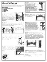
STEP 5. INSTALLING THE FRONT AND BACK DOOR PANEL (pictures pages 10-12)
Starting from the peak, disconnect the cross rail from the 3-way top connector. Place exposed
rope at the top of the panel over the 3-way connector and under the cross pole as shown in Detail P.
At each corner remove the cross rail and pull the door fabric around to the inside, placing the 3-way
connector through the opening in the fabric as shown in Detail O. Reconnect the cross rails.
Find the corner upright with the holes below the yellow … Sticker.
Insert the S hook with the yellow Label in the hole with the yellow label as in Detail 17
On the bent corner leg you will see a red label next to the hole. Insert the eye hook with the red ...
label. Diagram P. The eye hook should be facing the outside of the shelter.
Put the nut and washer on the eye hook on the inside of the shelter (sometimes the washer and nut
are preinstalled). The open end of the eye hook should be facing down. Leave the nut loose or hand
tighten enough to hook the door and cover rope into it. Detail P and 13
There is a large loop and a small loop on the rope on each side of the door panels. Detail 13 & 14
Find the small loop on the door with the red label and hook it into the eye hook with the red label.
Center the door. Detail 12
The bottom of the door should be just above the eye hook and the bottom corner leg. Detail 23
Take the rope on the other side of the door that has the big loop (you will see 2 red labels on the
door rope before the big loop). Hook the rope in the eye hook with the red label. Detail 28
Hook the big loop with the yellow label on the corner upright S hook with the yellow label on it.
Detail 22
Take the end of the rope with the green ... label and ball and pull up to make the big loop with the
yellow label smaller. This will tighten the door to the frame. After making the door snug, Detail 19,
22 & 28. You can pull all around the inside corners of the door to even up the door on the frame.
The bottom of the door should be just above the eye hook and above the bottom corner leg. This
will ensure the door will not rub on the ground. Detail 23
Pull up on the rope again so the door is tight on the frame and tie a few knots to secure the rope.
Repeat the same for the back panel.
Visit Shelterit.com for installation Video

Page 10
121008-212711 2017-05-18
Inside View
Door Panel
Cable rope comes
looped & ready to use
BIG Loop
SMALL Loop
N
O
P
P
O
Cable rope inside
door/end panel
Cable rope UNDER
end tube
OUTSIDE of shelter
The CABLE ROPES for the DOOR/END PANEL and COVER will BOTH hook onto the EYE HOOKS
INSIDE of shelter
INSIDE of shelter
Through Loop and
Pull to tighten
Tie o cover rope.
Door/End Panel rope
loop onto eye hooks
tighten and tie.
OUTSIDE of shelter

Page 11
121008-212711 2017-05-18
- 10 -

Page 12
121008-212711 2017-05-18
- 11 -
INSTALLING THE FRONT AND BACK PANEL Visit Shelterit.com for installation Video
Starting from the peak, disconnect the Cross Rail from the 3-way top connector. Place exposed Rope at the top of the panel over the 3-way
connector and under the cross pole as shown in Detail P above.. At each corner remove the Cross Rail and pull the door fabric around to
the inside, placing the 3-way connector through the opening in the fabric as shown in Detail O. Reconnect the cross rails.
Find the corner upright with the holes below to the yellow….. sticker.
Make sure the hole is facing in.
Insert the S hook with yellow ….. label in the hole with the Yellow ….. Label Detail 17
On the bent corner leg you will see a red ….. label next to the hole.
Insert the eye hook with the red ….. label on it. See Diagram P
The Eye hook should be facing the outside of the shelter.
Put the nut and wash on the eye hook on the inside of the shelter, sometimes the washer and nut are preinstalled. The open end of the eye
hook should be facing down and leave the nut loose or hand tight enough to hook the door and cover rope into it Detail P and 13
There is a large loop and a small loop on the rope on each side of the door panels Detail 13 & 14
Find the small loop on the door rope with the red ….. label and hook it into the eye hook with the red ….. label
Center the door Detail 12
The bottom of the door should be just above the eye hook and the bottom corner leg Detail 23
Take the rope on the other side of the door that has the big loop.
You will see 2 red ….. labels on the door rope before the big loop
Hook the rope in the Eye hook with the red ….. label Detail 28
Hook the big loop with the yellow ….. label on the corner upright S hook with the yellow ….. label on it Detail 22
Take the end of the rope with the green ….. label and ball and pull up to make the big loop with the yellow ….. label smaller.
Visit Shelterit.com for installation Video

Page 13
121008-212711 2017-05-18
STEP 6. INSTALLING THE COVER
Two people, each positioned approximately one-third into the center of the cover, carefully pull the
cover over the frame.
When reaching the peak, use a step stool or ladder to pass over this height.
Pull the cover over the frame so the rope in the pocket is in the front and back of the shelter, not on
the side of the shelter.
The 4 corner ropes should be in the 4 corners
When the roof tarp is in position the empty cross rail pockets should be on the side of the shelter
near the ground.
Installation Tip; Visually check all pipes of the frame to ensure they are fully inserted into the next pipe before in-
stalling cover. Pipes may separate during installation of end covers and prevent proper installation of the main cover.

Page 14
121008-212711 2017-05-18
STEP 7. INSTALLING LOWER CROSS RAILS INTO THE MAIN COVER
The shelter cover is manufactured with hear-welded pipe pocket sleeves along the lower wall of each
side (white color faces inside the shelter).
NOTE: Be sure all nuts are facing the interior side of the shelter to avoid tearing the cover and
Disconnect the lower cross rails and clamps and insert the cross rails into the pockets of the cover and
reassemble the clamps onto the frame hand tighten. Both sides of the cross rails on the shelter should be
approximately equal heights from the ground.
- 14 -
Step 7: Installing Lower Cross Rails into the main cover
The shelter cover is manufactured with heat-welded pipe pocket sleeves along the lower wall of each side (white color faces inside the
shelter,
Disconnect the lower cross rails and clamps and insert the cross rails in the pockets of the cover and reassemble the clamps to the frame
hand tight. Both sides of cross rails on the shelter should be approximately equal heights from the ground.
a) NOTE: Be sure all nuts are facing the interior side of the shelter to avoid tearing the cover and doors.
.

Page 15
121008-212711 2017-05-18
COVER TENSIONING
Find the ropes coming out of the 4 corners of the cover with the big loops, yellow ... label
You will see 2 red ... labels on the rope before the big loop, Detail 24 & 20
Hook the cover rope that has the 2 red labels in the same eye hook that you used for the door on the
outside of the shelter, Detail 20
After hooking the rope to the eye hook with the red label, bring the rope under the door, Detail 23
Hook the big loop with the yellow label on the same S hook the door is hooked on
Both door rope and cover rope will be on the same S hook, Detail 21
Before pulling the cover tight, even up the cover on all 4 sides
Make sure the side pocket for the cross rails that run front to back on the inside of the shelter are
equal to the ground
Take the end of the rope with the green ... label and ball, and pull up to make up the big loop with the
yellow label smaller. This will tighten the cover to the frame, Detail 19
Lightly and temporarily tie off the rope with a knot
Walk around the shelter to make sure the cover and door are even
Do a nal tightening of the cover to the frame. Firmly pull up so the rope is tight and tie off the rope
around the main rope with a few knots, Detail 19
After the cover is tightened on the 4 corners with the ropes, push and slide the bottom clamps down
that are connected to the side cross rails to snug the sides of the cover to the frame
Tighten the bolts of the cross rail clamps
- 15 -
- 15 -

Page 16
121008-212711 2017-05-18
STEP 8. SQUARE AND ANCHORING THE SHELTER
a. Ensure the frame is in the nal desired location
b. Check the measurement of 12’ wide in the front and back of the shelter
c. Take a diagonal measurement, cross-corner to cross-corner. When these 2 measurements are
equal the shelter is square. If not equal, tap the corner leg of the longer measurement with the
rubber mallet, in the direction of the diagonally opposite leg to push (decrease) the length of the
distance. Repeat (always taping against the longer measure) until both diagonals are equal
d. Once equal, check the width measurements again to ensure all are correct
e. Next, at the curved feet of the shelter install anchors by
screwing the temporary removable anchor
into the ground and to the inside the shelter
f. Secure with wire cable and cable clamp, Diagram M at right
It is recommended that you buy permanent anchors for the shelter
Visit Shelterit.com for permanent anchors and replacement parts
PLEASE RE-READ ALL WARNINGS CONTAINED ON PAGE 3 OF THESE INSTRUCTIONS.
SAVE THESE INSTRUCTIONS FOR FUTURE USE
To dismantle, execute all instructions in reverse order.
Store your shelter in a cool, dry location between seasons to prolong usable life of all components.
Components are not equally durable and will require replacement over time at differing intervals.
- 17 -
Step 8: Square and Anchoring the Shelter
a) Ensure the frame is in the final desired location.
b) Check the measurement of 10’ in the front and back of the shelter.
c) Take a diagonal measurement, cross-corner to cross-corner. When these two measurements are equal the shelter is square. If
not equal, tap the corner leg of the longer measurement with the rubber mallet, in the direction of the diagonally opposite leg to
push (decrease) the length of the distance. Repeat (always taping against the longer measure) until both diagonals are equal.
d) Once equal, check the width measurements again to ensure all are correct
e) Next, at the curved feet of the shelter install anchors, by screwing the Temporary removable anchors in to the ground and to the
inside of the shelter.
f) Secure with wire cable and cable clamp as shown in Diagram M below.
It is recommended that you buy permanent anchors for the shelter
Visit Shelterit.com for permanent anchors and replacement parts
PLEASE RE-READ ALL WARNINGS CONTAINED ON PAGE 3 OF THESE INSTRUCTIONS. SAVE THESE
INSTRUCTIONS FOR FUTURE USE.
To dismantle, execute all instructions in reverse order.
Store your shelter in a cool, dry location between seasons to prolong usable life of all components. Components are not equally durable
and will require replacement over time at differing intervals.

Page 17
121008-212711 2017-05-18
-18 -
LIMITED WARRANTY
This product is guaranteed for 1 year from the date of original retail purchase against defects in materials and workmanship.
Subject to the conditions and limitations described below, this product, must be returned with proof of purchase within the stated warranty period and if
covered under this warranty, will be replaced (fully or partially with the same model or one of equal value or specification) at the Manufacturer’s option.
Liability is restricted to repair or replacement only and does not include any related labor costs of installation, dismantling, repair or transportation costs.
These warranties are subject to the following conditions and limitations:
a) A bill of sale verifying the purchase and purchase date must be provided.
b) This warranty will not apply to any product or part thereof which is worn, broken or which has become inoperative due to abuse, misuse, accidental
damage, neglect or lack of proper installation, operation or maintenance (as outlined in the applicable owner’s manual or operating instructions) or
which is being used for industrial, professional, commercial or rental purposes.
c) This warranty will not apply to normal wear and tear or to expendable parts or accessories that may be supplied with the product which are expected
to become inoperative or unusable after a reasonable period of use.
d) This warranty will not apply to routine maintenance and consumable items such as the cover, rope , nuts, bolts, etc.
e) This warranty will not apply where damage is caused by repairs made or attempted by others (i.e. persons not authorized by the manufacturer).
f) This warranty will not apply to any product that was sold to the original purchaser as a reconditioned or refurbished product (unless otherwise
specified in writing).
g) This warranty will not apply to any product or part thereof if any part from another manufacturer is installed therein or any repairs or alterations have
been made or attempted by unauthorized persons.
h) This warranty will not apply to normal deterioration of the exterior finish, such as, but not limited to, scratches, dents, paint chips, or to any corrosion or
discolouring by heat, cold, abrasive and chemical cleaners.
i) This warranty will not apply to component parts sold by and identified as the product of another company, which shall be covered under the other
product manufacturer’s warranty, if any.
Additional Limitations
This warranty applies only to the original purchaser and may not be transferred. Neither the retailer nor the manufacturer shall be liable for any other expense,
loss or damage, including, without limitation, any indirect, incidental, consequential or exemplary damages arising in connection with the sale, use or inability
to use this product.
Notice to Consumer
This warranty gives you specific legal rights, and you may have other rights, which may vary from province to province state to state. The provisions
contained in this warranty are not intended to limit, modify, take away from, disclaim or exclude any statutory warranties set forth in any applicable provincial
or federal legislation.
Parts Alert!
If you have a question or if there are missing parts, please call:
203-591-9032
Or email Service@shelterit.com
Monday-Friday 9:00am-5:00 p.m. EST
Missing parts will be sent to you via courier.
Visit ShelterIt.com for instructional video
DO NOT RETURN TO STORE!

Page 18
121008-212711 2017-05-18
/