Page is loading ...

ShelterLogic, LLC
150 Callender Road
Watertown, CT 06795
www.shelterlogic.com
1-800-524-9970
1-800-559-6175
Canada:
Page 8
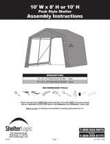
Assembly Instructions
10' W x 8' H or 10' H
Peak Style
Frame Assembly
Before you start: 2+ individuals recommended for assembly, approximate time 3 hours.
Recommended tools: Power Drill, Safety Glasses, Rope, Tape Measure, Ratchet with Socket Set,
Adjustable Wrench, Step Ladder, Rubber Mallet, Utility Knife, 5/8 Concrete Drill Bit, Sledge Hammer.
05-10ET13-0A
05-10ET13-0A
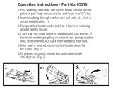
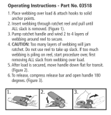
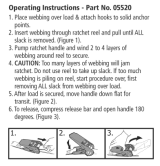
10. SECURING YOUR COVER:
A. Install the “S”- hook from the ratchet assembly into the legs of
the shelter. Pull the webbing carefully to remove the slack from the
cover. Do not to pull the webbing through the opposite side of the
cover.
B. Insert the webbing through the spindle of the ratchet and pull
tight. See Detail O. Wind the ratchet until the webbing overlaps
itself. Repeat these steps on the opposite side, then repeat this
on the back side of the shelter.
C. When all of the corners are secured, adjust the cover front to
back so that it is centered. When the cover is centered, tighten all
of the ratchets. Do this in an “X” pattern to be sure it is tightened
evenly. See Detail O.
D. Install the cover rails (10110) by inserting them into the pipe
pockets on each side of the cover. Bolt (10115) the rails to the ribs
using the 3-way and 4-way clamps as shown in Detail P. Check
that the rails are evenly spaced 8” above the ground on both
sides. Push down on the cover rails and connectors, one at a
time, to tighten the bolted clamps and the cover.
IMPORTANT: Install bolt caps (10150) on exposed bolts on side
rails and wind braces to prevent injury.
DETAIL O
OUTSIDE
CORNER
VIEW
10115
01010
11102
10115
10111
01010
DETAIL P
NOTE: CHECK THAT
YOUR COVER IS
CORRECTLY PLACED
ON THE FRAME.
The ShelterLogic
®
logo should line
up on the left front and right rear
corners near the top rail. If the logo
is not legible and positioned as
shown as “incorrect”, the cover has
not been put on the frame correctly.
CORRECT
INCORRECT
Check and
tighten Ratchets
and Cross Rails
monthly to ensure
the cover is tight.
Cover Tightening Tip
clamps
clamps
CORNER LEG
MIDDLE LEG
WARNING: Serious injury to persons or property could result if cover is installed and shelter is not
completed and is left unattended. Shelter must be securely anchored until completed.
10110

Page 3Page 2
05-10ET13-0A
05-10ET13-0A
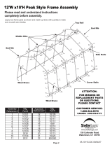
10'W x 10'H Peak Style Frame Assembly
Please read and understand instructions completely before assembly.
Layout out frame parts as shown.
10'W x 8'H Peak Style Frame Assembly
Please read and understand instructions completely before assembly.
Layout out frame parts as shown.
ATTENTION:
FOR MISSING OR
REPLACEMENT PARTS
OR QUESTIONS, PLEASE
CONTACT
CUSTOMER SERVICE:
1.800.524.9970
CANADA 1.800.559.6175
ATTENTION:
FOR MISSING OR
REPLACEMENT PARTS
OR QUESTIONS, PLEASE
CONTACT
CUSTOMER SERVICE:
1.800.524.9970
CANADA 1.800.559.6175
END RIB
CROSS
RAIL
TOP RAIL
MIDDLE RIBS
END RIB
WIND
BRACE
COVER RAIL
10' W X 8' H
10' W X 10' H
END RIB
CROSS
RAIL
TOP RAIL
MIDDLE RIBS
END RIB
WIND
BRACE
COVER RAIL
ITEM
NO.
DESCRIPTION
PART NO.
1
2
3
4
5
6
7
8
9
10
11
12
13
14
15
16
17
18
19
20
21
22
23
SWED.UPRIGHT TUBE 67 3/4"X1-5/8"D. 1 END
TOP BEND TUBE 15"X1-5/8" DIA.
SIDE BEND TUBE 15"X1-5/8" DIA.
RAFTER PIPE, 42X1190XT1,4 SWG BOTH ENDS GRY
CORNER UPRIGHT TUBE 57 3/4"X1-5/8" DIA.
BEND CORNER LEG 21"X1-5/8" DIA.
CROSS RAIL 48-1/2"X1.163",PLAIN ENDS 2 H
CROSS RAIL 50-1/2"X1.163", 1 SWDG 2 HOLE
CROSS RAIL PLAIN END 47"X1-1/8" DIA.
CROSS RAIL PLAIN ENDS 45 3/4"L, 2 HOLES
CROSS RAIL SWEDGED 48 7/8"X1-1/8" DIA.
BASE FOOT, 1-3/8 STEEL, GRY
3-WAY TOP CONNECTOR
3-WAY COVER RAIL CLAMP 1 5/8" PIPE
4-WAY COVER RAIL CLAMP
WIND BRACE FLAT ENDS 62-3/4"X1-1/8"DIA.
SHELTERLOCK ANTI-RACK DEVICE 42X28MM
BOLT, CARRIAGE,1/4"X1-5/8"
BOLT, CARRIAGE 1/4"x2"
BOLT, CARRIAGE 1/4" X 3"
BOLT, LADDER RD,F/TOPCRESTS,1/4"X3 1/2"L
NUT, HEX, 1/4-20
ANCHOR, AUGER 3"X15" WITH CABLE & CLAMP
10126
10131
10132
800464
10127
10128
02031
02030
10134
10110
10133
10113
10121
10112
10111
10135
800260
10115
10114
00670
00669
01010
00847
BOLT CAPS
24
10150
6
24
5
24
7
13
19
1
12
24
24
16
11
4
18
21/22
8
21/22
3
3
19
24
23
23
24
21/22
13
9
2
5
24
20
5
1
7
8
20
20
6
14
10
10
10
15
14
12
6
5
24
24
16
3
17
17
3
19
19
4
4
ITEM
NO.
DESCRIPTION
PART NO.
1
2
3
4
5
6
7
8
9
10
11
12
13
14
15
16
17
18
19
20
21
22
23
SWED.UPRIGHT TUBE 67 3/4"X1-5/8"D. 1 END
TOP BEND TUBE 15"X1-5/8" DIA.
SIDE BEND TUBE 15"X1-5/8" DIA.
RAFTER PIPE, 42X1190XT1,4 SWG BOTH ENDS GRY
CORNER UPRIGHT TUBE 57 3/4"X1-5/8" DIA.
BEND CORNER LEG 21"X1-5/8" DIA.
CROSS RAIL 48-1/2"X1.163",PLAIN ENDS 2 H
CROSS RAIL 50-1/2"X1.163", 1 SWDG 2 HOLE
CROSS RAIL PLAIN END 47"X1-1/8" DIA.
CROSS RAIL PLAIN ENDS 45 3/4"L, 2 HOLES
CROSS RAIL SWEDGED 48 7/8"X1-1/8" DIA.
BASE FOOT, 1-3/8 STEEL, GRY
3-WAY TOP CONNECTOR
3-WAY COVER RAIL CLAMP 1 5/8" PIPE
4-WAY COVER RAIL CLAMP
WIND BRACE FLAT ENDS 62-3/4"X1-1/8"DIA.
SHELTERLOCK ANTI-RACK DEVICE 42X28MM
BOLT, CARRIAGE,1/4"X1-5/8"
BOLT, CARRIAGE 1/4"x2"
BOLT, CARRIAGE 1/4" X 3"
BOLT, LADDER RD,F/TOPCRESTS,1/4"X3 1/2"L
NUT, HEX, 1/4-20
ANCHOR, AUGER 3"X15" WITH CABLE & CLAMP
10126
10131
10132
800464
10127
10128
02031
02030
10134
10110
10133
10113
10121
10112
10111
10135
800260
10115
10114
00670
00669
01010
00847
BOLT CAPS
24
10150
10223
25
UPRIGHT EXTENSION, 27” SWEDGED-1 SIDE 1 5/8 D.
6
24
5
24
7
13
19
1
12
24
24
16
11
4
18
21/22
8
21/22
3
3
19
24
23
23
24
21/22
13
9
2
5
24
20
5
1
7
8
20
20
6
14
10
10
10
15
14
12
6
5
24
24
16
3
17
17
3
19
19
4
4
25
25
25
25

Page 5Page 5
Page 4
05-10ET13-0A05-10ET13-0A
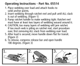
ASSEMBLY OF PEAK STYLE GARAGE SHELTER
NOTE FOR FRAME EXTENSION KIT: 10’ x 8’ is the base frame dimension. Your model may have more middle
ribs than shown in the illustrations. You will receive one extra rib for every extra 4 feet of building length that you
purchase. The basic frame assembly will remain the same. The cover will be the correct size for the length of the
building ordered.
1. PLOTTING AND SQUARING UP THE FRAME:
A. Before building your shelter, you should choose a at area
on your property and plot your shelter. Stake out the area for
the frame in the desired spot. Check that it measures 10’ in
width and the length would be determined by the size shelter
you purchased. Tie a rope diagonally from corner to corner.
B. Measure across area, end to opposite end. See Detail A.
The measurement A and B should be equal.
10'
10'
A
B
LENGTH
OF
BUILDING
DETAIL A
2. ASSEMBLE END AND MIDDLE RIBS:
DETAIL B
End Ribs
DETAIL C
Middle Ribs
#10114
2” Bolt
Item #19
All Connections
10' HIGH
8' HIGH
3. INSTALL SIDE RAILS AND SHELTERLOCK
™
STABILIZER BLOCKS:
A. Place assembled rst end rib in the staked area. Place the
ShelterLock
™
on the upright as shown in Detail D. From the
outside of the rib insert the bolt through the upright and then
through the ShelterLock
™
.
B. Place the plain end of the side rail over the bolt and nest
it into the ShelterLock
™
. Install the nut onto the bolt and
tighten. Repeat these steps for the opposite side and all of
the remaining ribs. The side rails for the last rib will have two
plain ends.
4. INSTALL WIND BRACES:
A. Attach wind brace between the end rib and the rst
middle rib as shown in Detail E. Bolts attached at the
cross rails should be inserted facing inside the shelter.
5. INSTALL TOP RAIL:
A. Place the rst top rail under each end rib and secure it
with a bolt as shown in Detail F. The same cross rail should
lay on top of the all middle ribs. Secure the rails to the frame
with the hardware indicated in Detail F. The top rail attached
to the last rib will be installed under the pipe.
DETAIL D
DETAIL E
DETAIL F
FIRST
MIDDLE
RIB
WIND BRACE
END RIB
00669
10210
Install the Top Rail
OVER all Middle Ribs
UNDER First and Last Ribs
A. Assemble end and middle ribs as shown in Detail B and Detail C.
Securely fasten all of the joints with the hardware indicated.
10121
10132
10132
10127
10127
10128
10128
10131
10132
10132
10126
10126
Fig. 2
800260
1010
10135
10135
800464
800464
800464
800464
10113
10113
10131
10132
10132
10126
10126
800464
800464
10113
10113
10223
10223
10132
10132
800464
800464
10223
10223
10128
10127
10127
10121
10128
#10114
2” Bolt
Item #19
All Connections
#10114
2” Bolt
Item #19
All Connections
#10114
2” Bolt
Item #19
All Connections
00670
02030
02030
02030
02030

Page 6
Page 7
05-10ET13-0A
05-10ET13-0A
6. SECURE BASE FEET:
A. Slide leg pipe over over the base feet, line up the holes in
the pipe with the holes in the feet and secure with the hard-
ware indicated in Detail G.
7. INSTALL AUGER ANCHORS:
A. Anchors must be placed inside shelter. Start at the corners
of the shelter. Insert a ¾” pipe or steel rod, through the eyelet
of the auger and screw the anchor into the ground. (If ground is
too hard, dig a hole with a shovel or post hole tool.)
OPTIONAL:
Fill with cement.
B. Space out the remaining anchors evenly along the length of
the shelter. Screw the anchor into the ground until the eyelet is
sticking out of the ground by 1-2” so it can be anchored to the
legs.
C. Wrap the cable provided through the eyelet of the anchor
and around the frame as indicated in Detail H. Secure the cable
with the clamps provided.
D. Repeat for middle legs by attaching cable around foot plates.
8. ZIPPER DOOR AND OR END PANEL INSTALLATION:
Secure
with bolt
and nut
DETAIL G
DETAIL H
A. Hold the end panel at the top center with the white inner
surface facing the inside of the shelter (if you have a white
shelter the inner surface has the visible weld seams).
B. Unscrew top rail from the top bend and place the webbing
in between. The top rail should pass through the loop of the
webbing. Reconnect top rail onto rib and secure it with the
screws indicated. See Detail I.
C. Remove the nut from the side rail and carefully pull
the side rail away from the ShelterLock
™
(pull away only
enough to pass the webbing through the connection). If
this connection has the wind brace on it remove the
wind brace end before pulling the side rail. Replace the
cross rail and wind brace. See Detail J. Replace the nut and
tighten. Repeat this on the other side.
D. At the bottom, where the webbing exits the pocket on
each side of end panel, pull webbing to remove the slack.
Be careful not to pull the webbing through the other side of
the panel.
E. Install the “S”- hook from the ratchet into the leg of the
shelter. Insert the webbing into the spindle of the ratchet
and pull tight. See Detail J. Wind the ratchet so that the web-
bing overlaps itself. Repeat this process on the other side of
the panel. Position the end panel so that it is centered on the
building.
F. Tighten the ratchets, alternating from one side to the other,
until the end panel is tight. Repeat these steps on the other
end of the building.
DETAIL I
INSIDE VIEW
SIDE VIEW
DETAIL J
9. INSTALLING THE COVER ON THE FRAME:
A. Lay the cover on the ground next to the
frame with the inside of the cover (the side with
the pipe pockets) facing down and the webbing
on the front and rear of the corner of the build-
ing. Position the cover so that it is centered on
the frame, front to back. See Detail K.
B. Fold over the side so the pipe pocket is now
accessible. Insert a cover pipe into the pipe
pocket slot, at the rst middle rib from the front
and the rst middle rib from the rear. Some of
the pipe will be exposed. For long buildings it
may be necessary to use additional pipes in the
middle. See Detail L. Remove pocket pipe to
install later.
C. Tie the rope on each of the exposed pipes
and throw the other end of the rope over the
frame. See Detail M.
D. Move to the other side of the frame and pull
the cover over the frame with the rope. This
may require two or more people. See Detail N.
Check that the Logo reads upright as shown.
DETAIL K
DETAIL L
DETAIL M
DETAIL N
END PANELS
NOT SHOWN
FOR CLARITY
10114
01010
Slit in fabric
folded around
frame and
cross rails
inserted
through slits
ROPE
END LEGS MIDDLE
LEGS
/