Page is loading ...

Page 3Page 2
®
GARAGE SHELTER:
™
®
GARAGE SHELTER................ .................PAGE 11
MISE EN GARDE-GARANTIE................................................................................................PAGE 12
WH..PAGE 13
3. INSTALLER LES BARRES TRANSVERSALES ET LES BLOQUES STABILISATEUR SHELTERLOCK
™
.
®
GARAGE SHELTER..................PAGE 20
PRECAUCIÓN-GARANTÍA.....................................................................................................PAGE 21
2. ENSAMBLE LAS CERCHAS TERMINALES Y LAS INTERMEDIAS..................................PAGE 24
3. INSTALE LOS LARGUEROS LATERALES Y LOS BLOQUES ESTABILIZADORES SHELTERLOCK
™
.... ...PAGE 25
THIS IS A TEMPORARY STRUCTURE AND NOT RECOMMENDED AS A PERMANENT STRUCTURE.
!
Please read instructions COMPLETELY before assembly. This Canopy MUST be anchored.
TABLE OF CONTENTS:
ÍNDICE DE MATERIAS
05-201133_13-0D
05-201133_13-0D
WARNING:
Prior to installation, consult with all local and municipal codes regarding the installation of temporary
shelters. Choose the location of your shelter carefully. Check for overhead utility lines, tree branches or
-
tools or instruments like rakes or shovels to remove snow. This could result in punctures to the cover.
CAUTION:
designed to offer protection from damage caused by the sun, light rain, tree sap, bird and animal
excrement, and light snow. It is not designed to hold loads from high winds, heavy snow or ice storms.
GUARANTEE:
Instant shelters carry a full 1 year limited warranty against defects in workmanship. Proper anchoring,
keeping cover tight and free of snow and debris is the responsibility of the consumer. SHELTERLOGIC
®
does not guarantee this temporary fabric shelter from high wind, heavy snow, and ice storms or other
acts of nature and is not responsible for damage to the unit or the contents. If extreme weather is fore-
cast, we recommend the cover be removed. Check with your insurance carrier for any damage as you
would for any other outdoor structure or personal property claims.
PROPER ANCHORING OF INSTANT GARAGE FRAME:
NOTE:
Make sure shelter frame and cover are properly anchored prior to installation. Periodically check the
shelter anchors or stakes to ensure stability of shelter. The preferred anchoring system includes the
use of auger style screw in or EZ hook anchors and cables/rope attached to each rib. Mobile home
anchors will also work. Any frame that is not anchored properly or securely has the potential to
become damaged by wind or snow and is not covered.
REPLACEMENT PARTS, ASSEMBLY, SPECIAL ORDERS:
Replacement parts and accessories are available for this and all SHELTERLOGIC
®
products. We
offer several anchoring kits for nearly any application including spare parts, as well as additional covers
and other accessories. Any Item purchased is shipped factory direct to your door, and is of high quality.
For more information, please call customer service department at 1-800-524-9970
Monday-Friday 8:30 AM-8:00 PM EST, Saturday-Sunday 8:30 AM-5:00 PM EST.
CARE AND CLEANING:
A tight cover will ensure longer life and performance. Always maintain a tight cover. Loose fabric can
accelerate deterioration of cover. Immediately remove any accumulated snow or ice from the roof
or harsh abrasive products to clean the fabric cover. Cover can be easily cleaned with mild soap and
water.
WARNINGS, CAUTIONS, CARE & CLEANING:

Page 5
12’W x 8’H (or 10’H) RoundTop
®
Frame Assembly
Please read and understand instructions completely before assembly.
Layout out frame parts as shown and match up items
with quantity to make sure no parts are missing.
Assembly
Reference #
1
2
3
4
5
8
Mfg.
Part #
10224
10225
02030
02031
10110
10111
Assembly
Reference #
9
10
11
12
13
14
15
Mfg.
Part #
10112
10205
10210
10114
10115
12'W x 8'H
ShelterLogic, LLC
150 Callender Road
Watertown, CT 06795
www.shelterlogic.com
Page 5
Page 4
05-201133_13-0D
05-201133_13-0D
12’W x 10’H (or 8’H) RoundTop
®
Frame Assembly
Please read and understand instructions completely before assembly.
Layout out frame parts as shown and match up items
with quantity to make sure no parts are missing.
ShelterLogic, LLC
150 Callender Road
Watertown, CT 06795
www.shelterlogic.com
ATTENTION:
FOR MISSING OR
REPLACEMENT PARTS
OR QUESTIONS, PLEASE
CONTACT
CUSTOMER SERVICE:
1.800.524.9970
CANADA 1.800.559.6175
Assembly
Reference #
1
2
3
4
5
8
9
10
11
12
13
14
15
Mfg.
Part #
10224
10225
10223
02030
02031
10205
10110
10111
10112
10210
10114
10115
5
4
5
3
12'W x 10'H
ATTENTION:
FOR MISSING OR
REPLACEMENT PARTS
OR QUESTIONS, PLEASE
CONTACT
CUSTOMER SERVICE:
1.800.524.9970
CANADA 1.800.559.6175
END RIB
SIDE RAIL
TOP RAIL
MIDDLE RIBS
END RIB
WIND
BRACE
WIND
BRACE
COVER RAIL
END RIB
SIDE RAIL
TOP RAIL
MIDDLE RIBS
END RIB
WIND
BRACE
COVER RAIL

ASSEMBLY OF ROUNDTOP
®
GARAGE SHELTER
05-201133_13-0D
05-201133_13-0D
NOTE FOR FRAME EXTENSION KIT: 12’ x 20’ x 8’ is the base frame dimension. Your model may have more
middle ribs than shown in the illustrations. You will receive one extra rib for every extra 4 feet of building length
that you purchase. The basic frame assembly will remain the same. The cover will be the correct size for the
length of the building ordered.
1. PLOTTING AND SQUARING UP THE FRAME:
on your property and plot your shelter. Stake out the area for
width and the length would be determined by the size shelter
you purchased. Tie a rope diagonally from corner to corner.
B. Measure across area, end to opposite end. See Detail A.
The measurement A and B should be equal.
12'
12'
A
B
LENGTH
OF
BUILDING
DETAIL A
2. ASSEMBLE END AND MIDDLE RIBS:
10224
10223
10225
10223
10224 10225
10223
10223
10224
10225
10224 10225
DETAIL B
End Ribs
DETAIL C
Middle Ribs
3-1/2” Bolt
2”
Bolt
#10210
3” Bolt
2”
Bolt
10' HIGH
8' HIGH
3-1/2” Bolt
2”
Bolt
#10210
3” Bolt
2”
Bolt
3. INSTALL SIDE RAILS AND SHELTERLOCK
™
STABILIZER BLOCKS:
ShelterLock
™
outside of the rib insert the bolt through the upright and then
through the ShelterLock
™
.
B. Place the plain end of the side rail over the bolt and nest
it into the ShelterLock
™
. Install the nut onto the bolt and
tighten. Repeat these steps for the opposite side and all of
the remaining ribs. The side rails for the last rib will have two
plain ends.
4. INSTALL WIND BRACES:
middle rib as shown in Detail E. Bolts attached at the
cross rails should be inserted facing inside the shelter.
5. INSTALL TOP RAIL:
end rib and secure it
lay on top of the all middle ribs. Secure the rails to the frame
to the last rib will be installed under the pipe.
10210
800260
01010
0
2
0
3
0
0
2
0
3
0
0
2
0
3
0
0
2
0
3
0
0
2
0
3
0
0
2
0
3
0
10205
10205
DETAIL D
DETAIL E
DETAIL F
FIRST
MIDDLE
RIB
WIND
BRACE
WIND
BRACE
END RIB
00669
10210
Install the Top Rail
OVER all Middle Ribs
UNDER First and Last Ribs
A. Assemble end and middle ribs as shown in Detail B and Detail C.
Securely fasten all of the joints with the hardware indicated.

Page 8
Page 9
05-201133_13-0D
05-201133_13-0D
6. SECURE BASE FEET:
A. Depending on the model purchased, your base feet will
bottom of the leg pole.
B. After installing the base feet, line up the holes in the leg to
the holes in the feet and secure with the hardware indicated
in Detail G.
7. INSTALL AUGER ANCHORS:
A. Anchors must be placed inside shelter. Start at the corners
of the shelter. Insert a ¾” pipe or steel rod, through the eyelet
of the auger and screw the anchor into the ground. (If ground is
too hard, dig a hole with a shovel or post hole tool.)
OPTIONAL:
Fill with cement.
B. Space out the remaining anchors evenly along the length of
the shelter. Screw the anchor into the ground until the eyelet is
sticking out of the ground by 1-2” so it can be anchored to the
legs.
C. Wrap the cable provided through the eyelet of the anchor
and around the frame as indicated in Detail H. Secure the cable
with the clamps provided.
D. Repeat for middle legs by attaching cable around foot plates.
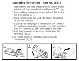
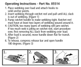
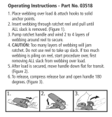
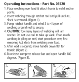
8. ZIPPER DOOR AND OR END PANEL INSTALLATION:
Secure
with bolt
and nut
DETAIL G
6. SECURE BASE FEET:
Detail G
7. INSTALL AUGER ANCHORS:
8. ZIPPER DOOR AND OR END PANEL
INSTALLATION:
Slits
A. Depending on the model purchased, your base feet will either fit onto
the outside of the leg pole, or slide into the bottom of the leg pole. After
installing the base feet line up the holes in the leg to the holes in
the feet and secure with the hardware indicated in Detail G.
A. Start at the corners of the shelter. Insert a ¾” pipe or steel rod,
through the eyelet of the auger and screw the anchor into the
ground. (Dig a hole with a shovel or post hole tool if ground is too
hard.) Optional: Fill with cement.
B. Space out the remaining anchors evenly along the length of the
shelter. Screw the anchor into the ground until the eyelet is sticking
out of the ground by 1-2” so it can be anchored to the legs.
C. Wrap the cable provided through the eyelet of the anchor and
around the frame as indicated in Detail H. Secure the cable with
the clamps provided.
A. Hold the end panel at the top center with the white inner
surface facing the inside of the shelter (if you have a white
shelter the inner surface has the visible weld seams).
B. Unscrew top rail from the top bend and place the webbing
in between. The top rail should pass through the loop of the
webbing. Reconnect top rail onto rib and secure it with the
screws indicated. See Detail I.
C. Remove the nut from the side rail and carefully pull the side
rail away from the ShelterLock
TM
(pull away only enough to
pass the webbing through the connection). If this connection
has the wind brace on it remove the wind brace end before
pulling the side rail. Replace the cross rail and wind brace.
See Detail J. Replace the nut and tighten. Repeat this on the
other side.
D. At the bottom, where the webbing exits the pocket on each
side of end panel, pull webbing to remove the slack. Be careful
not to pull the webbing through the other side of the panel.
E. Install the “S”- hook from the ratchet into the leg of the shelter.
Insert the webbing into the spindle of the ratchet and pull tight.
See Detail J. Wind the ratchet so that the webbing overlaps
itself. Repeat this process on the other side of the panel.
Position the end panel so that it is centered on the building.
F. Tighten the ratchets, alternating from one side to the other,
until the end panel is tight. Repeat these steps on the other end
of the building.
Secure with
Bolt and Nut
Detail H
END LEGS
MIDDLE
LEGS
Detail I
Slit in fabric
folded around
frame and cross
rails inserted
through slits
INSIDE VIEW
SIDE VIEW
Detail J
DETAIL H
A. Hold the end panel at the top center with the white inner
surface facing the inside of the shelter (if you have a white
shelter the inner surface has the visible weld seams).
B. Unscrew top rail from the top bend and place the webbing
in between. The top rail should pass through the loop of the
webbing. Reconnect top rail onto rib and secure it with the
screws indicated. See Detail I.
C. Remove the nut from the side rail and carefully pull
the side rail away from the ShelterLock
™
(pull away only
enough to pass the webbing through the connection). If
this connection has the wind brace on it remove the
wind brace end before pulling the side rail. Replace the
tighten. Repeat this on the other side.
D. At the bottom, where the webbing exits the pocket on
each side of end panel, pull webbing to remove the slack.
Be careful not to pull the webbing through the other side of
the panel.
E. Install the “S”- hook from the ratchet into the leg of the
shelter. Insert the webbing into the spindle of the ratchet
-
bing overlaps itself. Repeat this process on the other side of
the panel. Position the end panel so that it is centered on the
building.
until the end panel is tight. Repeat these steps on the other
end of the building.
DETAIL I
Slits
Slit in fabric
folded around
frame and
cross rails
inserted
through slits
INSIDE VIEW
SIDE VIEW
DETAIL J
9. INSTALLING THE COVER ON THE FRAME:
A. Lay the cover on the ground next to the
frame with the inside of the cover (the side with
the pipe pockets) facing down and the webbing
on the front and rear of the corner of the build-
ing. Position the cover so that it is centered on
the frame, front to back. See Detail K.
accessible. Insert a cover pipe into the pipe
may be necessary to use additional pipes in the
middle. See Detail L. Remove pocket pipe to
install later.
C. Tie the rope on each of the exposed pipes
and throw the other end of the rope over the
frame. See Detail M.
D. Move to the other side of the frame and pull
the cover over the frame with the rope. This
may require two or more people. See Detail N.
Check that the Logo reads upright as shown.
DETAIL K
DETAIL L
DETAIL M
DETAIL N
END PANELS
NOT SHOWN
FOR CLARITY
10114
01010

Page 10
Page 11
05-201133_13-0D
05-201133_13-0D
LES TRADUCTIONS FRANÇAISES
D’INSTRUCTION D’ ASSEMBLAGE
Autres brevets en instance
Lire TOUTES les instructions avant de monter.
Cet abri DOIT être bien ancré.
Avant de commencer: Il faut 2+ personnes ou plus pour le montage qui prend environ 3 heures.
Outils recommandés:
Escabot/Echelle, Maillet de caoutchouc, Couteau d' utilitaire.
10. SECURING YOUR COVER:
A. Install the “S”- hook from the ratchet assembly into the legs of
the shelter. Pull the webbing carefully to remove the slack from the
cover. Do not to pull the webbing through the opposite side of the
cover.
B. Insert the webbing through the spindle of the ratchet and pull
itself. Repeat these steps on the opposite side, then repeat this
on the back side of the shelter.
C. When all of the corners are secured, adjust the cover front to
back so that it is centered. When the cover is centered, tighten all
of the ratchets. Do this in an “X” pattern to be sure it is tightened
D. Install the cover rails (10110) by inserting them into the pipe
pockets on each side of the cover. Bolt (10115) the rails to the ribs
using the 3-way and 4-way clamps as shown in Detail P. Check
that the rails are evenly spaced 8” above the ground on both
sides. Push down on the cover rails and connectors, one at a
time, to tighten the bolted clamps and the cover.
IMPORTANT: Install bolt caps (10150) on exposed bolts on side
rails and wind braces to prevent injury.
DETAIL O
OUTSIDE
CORNER
VIEW
10115
01010
11102
10115
10111
01010
DETAIL P
NOTE: CHECK THAT
YOUR COVER IS
CORRECTLY PLACED
ON THE FRAME.
The ShelterLogic
®
logo should line
up on the left front and right rear
corners near the top rail. If the logo
is not legible and positioned as
shown as “incorrect”, the cover has
not been put on the frame correctly.
CORRECT
INCORRECT
Check and
tighten Ratchets
and Cross Rails
monthly to ensure
the cover is tight.
Cover Tightening Tip
CLAMPS
CLAMPS
CORNER LEG
MIDDLE LEG
WARNING: Serious injury to persons or property could result if cover is installed and shelter is not
completed and is left unattended. Shelter must be securely anchored until completed.
10110

05-201133_13-0D
05-201133_13-0D
3. INSTALLER LES BARRES TRANSVERSALES ET
LES BLOQUES STABILISATEUR SHELTERLOCK
™
:
A. Positionner la première ossature assemblée dans
™
en position
ShelterLock
™
.
B. Placer le bout de la barre transversale par dessus le
boulon et le positionner dans le ShelterLock
™
ainsi que le reste des ossatures. Les barres transversales
pour la dernière ossature devrait avoir 2 bouts normal.
4. INSTALLEZ LES RENFORT CONTRE VENT:
première ossatures centrale comme montré dans le
détail E. Les boulons inséré dans les barres transver
-
5. INSTALLER LA BARRE SUPÉRIEUR:
A. Positionner la première barre supérieur sous
bout
ossatures centrales.
Sécurisez les barres en utilisant la quincaillerie indiquée dans
10210
800260
01010
0
2
0
3
0
0
2
0
3
0
0
2
0
3
0
0
2
0
3
0
0
2
0
3
0
0
2
0
3
0
10205
10205
DÉTAIL D
DÉTAIL E
8. PORTE Á GLISSIÈRE ET PANNEAU ARRIÈRE:
A. Tenez le panneau arrière en haut du centre du panneau
abris blanc, le coté intérieur est le coté avec les coutures).
B. Déboulonnez la barre supérieure du connecteur et placer
la sangle entre les deux. La barre supérieur doit passer dans
Détail I.
-
passer la sangle entre le SHELTERLOCK
™
et la barre. Si
vous avez un renfort á cet endroit, enlever le avant de
retirer la barre transversale. Remettez le renfort et la
D. En bas du panneau, la où les sangles sortent de chaque
coté du panneau, tirez sur les sangles pour bien les tendres.
-
panneau. Positionner le panneau de façon bien centré sur
DÉTAIL I
Fentes
Fente dans la
toiture autour
de la char-
pente et barre
transversale
insérée dans
la fente
DÉTAIL J
OSSATURES
CENTRALES
RENFORT
CONTRE VENT
OSSATURE
DE BOUT
DÉTAIL F
00669
10210
Installez la barre supérieur
AU DESSUS des ossatures centrales et
AU DESSOUS des ossatures de bouts.
6. SÉCURISEZ LES PIEDS:
A. Selon le modèle acheté, les pieds sera installer ou sur
les poteaux.
B. Après avoir installé les pieds, alignez les trous des pieds
avec les trous des poteaux et sécurisez avec la quincaillerie
indiquée dans le détail G.
7. INSTALLATION DES ANCRES:
-
si le sol est trop dure.) FACULTATIF: Remplir de ciment.
les ancres dans le sol de façon a ce que 1” ou 2” soit en dehors
de lu sol de façon a ce que vous puissiez y accrocher les pieds.
et autour de la charpente comme montré dans le détail H.
Sécurisez le câble avec la pince fournie.
D. Répéter pour les jambes de milieu en attachant le câble
autour des plaques de pied.
Sécurisé
avec
boulons
et écrous
DÉTAIL G
6. SECURE BASE FEET:
Detail G
7. INSTALL AUGER ANCHORS:
8. ZIPPER DOOR AND OR END PANEL
INSTALLATION:
Slits
A. Depending on the model purchased, your base feet will either fit onto
the outside of the leg pole, or slide into the bottom of the leg pole. After
installing the base feet line up the holes in the leg to the holes in
the feet and secure with the hardware indicated in Detail G.
A. Start at the corners of the shelter. Insert a ¾” pipe or steel rod,
through the eyelet of the auger and screw the anchor into the
ground. (Dig a hole with a shovel or post hole tool if ground is too
hard.) Optional: Fill with cement.
B. Space out the remaining anchors evenly along the length of the
shelter. Screw the anchor into the ground until the eyelet is sticking
out of the ground by 1-2” so it can be anchored to the legs.
C. Wrap the cable provided through the eyelet of the anchor and
around the frame as indicated in Detail H. Secure the cable with
the clamps provided.
A. Hold the end panel at the top center with the white inner
surface facing the inside of the shelter (if you have a white
shelter the inner surface has the visible weld seams).
B. Unscrew top rail from the top bend and place the webbing
in between. The top rail should pass through the loop of the
webbing. Reconnect top rail onto rib and secure it with the
screws indicated. See Detail I.
C. Remove the nut from the side rail and carefully pull the side
rail away from the ShelterLock
TM
(pull away only enough to
pass the webbing through the connection). If this connection
has the wind brace on it remove the wind brace end before
pulling the side rail. Replace the cross rail and wind brace.
See Detail J. Replace the nut and tighten. Repeat this on the
other side.
D. At the bottom, where the webbing exits the pocket on each
side of end panel, pull webbing to remove the slack. Be careful
not to pull the webbing through the other side of the panel.
E. Install the “S”- hook from the ratchet into the leg of the shelter.
Insert the webbing into the spindle of the ratchet and pull tight.
See Detail J. Wind the ratchet so that the webbing overlaps
itself. Repeat this process on the other side of the panel.
Position the end panel so that it is centered on the building.
F. Tighten the ratchets, alternating from one side to the other,
until the end panel is tight. Repeat these steps on the other end
of the building.
Secure with
Bolt and Nut
Detail H
END LEGS
MIDDLE
LEGS
Detail I
Slit in fabric
folded around
frame and cross
rails inserted
through slits
INSIDE VIEW
SIDE VIEW
Detail J
DÉTAIL H
10114
01010
RENFORT
CONTRE
VENT
POTEAUX
DE BOUT
POTEAUX
CENTRAUX
VUE LATÉRALE
VUE INTÉRIEURE

05-201133_13-0D
05-201133_13-0D
8. INSTALACIÓN DE LA PUERTA DE
CREMALLERA O DEL PANEL TERMINAL:
A. Sostenga el panel terminal en la parte superior al centro
-
interior tiene visibles las uniones soldadas).
B. Desatornille el larguero superior del codo superior y
coloque el tejido en el medio. El larguero superior debe
pasar a través de la anilla del tejido. Reconecte el larguero
superior en la cercha y asegúrelo con los tornillos indicados.
C. Retire la tuerca del larguero lateral y cuidadosamente
hale el larguero lateral separándolo del ShelterLock
™
(hale
la conexión). Si esta conexión tiene colocada la rios-
tra contra viento, retire el extremo de la riostra contra
viento antes de halar el larguero lateral.
Repita para el otro lado.
D. En la parte inferior, donde el tejido sale del compartimien
-
to en cada lado del panel terminal, hale el tejido para tensar.
Tenga cuidado de no halar el tejido a través del otro lado del
panel.
E. Instale el gancho en “S” del trinquete en la pata del cobe
-
rtizo. Inserte el tejido en el huso del trinquete y hale hasta
trinquete de modo que el tejido se solape sobre sí mismo.
Repita este proceso en el otro lado del panel. Ubique el
panel terminal de modo que esté centrado en la unidad.
que el panel terminal quede ajustado. Repita estos pasos en
el otro extremo de la unidad.
DETAILLE I
Aberturas
La tela con
incisión dobl
ada alrededor
de la estructura
y los largueros
transversales
insertados a
través de las
incisiones.
VISTA INTERIOR
VISTA LATERAL
DETAILLE J
9. INSTALACIÓN DE LA CUBIERTA EN LA ESTRUCTURA:
A. Coloque la cubierta en la tierra al lado de la
estructura con la parte interior de la cubierta
(el lado con los compartimientos para el tubo)
orientada hacia abajo y el lado del tejido del
frente y posterior de la esquina de la unidad.
Coloque la cubierta de modo que esté centrada
en la estructura, desde el frente hacia atrás.
B. Doble el costado de modo que el
compartimiento del tubo quede ahora accesible.
Inserte un tubo de cubierta en la ranura del
compartimiento del tubo en la primera cercha
intermedia desde el frente y la primera cercha
intermedia desde la parte posterior. Parte del
tubo queda expuesto. Para unidades largas
puede ser necesario utilizar tubos adicionales en
el tubo del compartimiento para instalarlo más
tarde.
C. Ate la cuerda en cada uno de los tubos expu-
estos y pase el otro extremo de la cuerda sobre
D. Cámbiese al otro lado de la estructura y hale
la cubierta sobre la estructura con la cuerda.
Este procedimiento puede requerir de dos
quede según se ilustra.
DETAIL K
DETAIL L
DETAIL M
DETAIL N
LOS PANELES
DE EXTREMO
NO SE ILUS-
TRAN PARA
FACILIDAD DE
COMPRENSIÓN
6. ASEGURE LAS PATAS DE BASE:
A. Dependiendo del modelo que haya comprado, la pata de
base encajará en la parte externa del poste o se deslizará
dentro de la parte inferior del poste.
B. Después de instalar las patas de base, alinee los
agujeros en la pata con los de las patas base y asegure
7. INSTALE LOS ANCLAJES DE BARRENA:
A. Los anclajes deben ubicarse dentro del cobertizo. Comience en
las esquinas del cobertizo. Inserte un tubo de 1,9 cm o una varilla
de acero a través de la armella de la barrena y atornille el anclaje
en la tierra. (Cave un agujero con una pala o herramienta para
cavar postes si la tierra está demasiado dura).
OPCIONAL: Llene con cemento.
B. Separe uniformemente los anclajes restantes a lo largo del
cobertizo. Atornille el anclaje a la tierra hasta que la armella salga
de la tierra 2,5-5,1 cm de modo que puede anclarse a las patas.
C. Enrolle el cable que se suministra a través de la armella del
detallada H. Asegure el cable con las abrazaderas que se
suministran.
D. Repita para piernas medianas conectando cable alrededor
de platos de pie.
Fije con
perno y
tuerca
DETAILLE G
6. SECURE BASE FEET:
Detail G
7. INSTALL AUGER ANCHORS:
8. ZIPPER DOOR AND OR END PANEL
INSTALLATION:
Slits
A. Depending on the model purchased, your base feet will either fit onto
the outside of the leg pole, or slide into the bottom of the leg pole. After
installing the base feet line up the holes in the leg to the holes in
the feet and secure with the hardware indicated in Detail G.
A. Start at the corners of the shelter. Insert a ¾” pipe or steel rod,
through the eyelet of the auger and screw the anchor into the
ground. (Dig a hole with a shovel or post hole tool if ground is too
hard.) Optional: Fill with cement.
B. Space out the remaining anchors evenly along the length of the
shelter. Screw the anchor into the ground until the eyelet is sticking
out of the ground by 1-2” so it can be anchored to the legs.
C. Wrap the cable provided through the eyelet of the anchor and
around the frame as indicated in Detail H. Secure the cable with
the clamps provided.
A. Hold the end panel at the top center with the white inner
surface facing the inside of the shelter (if you have a white
shelter the inner surface has the visible weld seams).
B. Unscrew top rail from the top bend and place the webbing
in between. The top rail should pass through the loop of the
webbing. Reconnect top rail onto rib and secure it with the
screws indicated. See Detail I.
C. Remove the nut from the side rail and carefully pull the side
rail away from the ShelterLock
TM
(pull away only enough to
pass the webbing through the connection). If this connection
has the wind brace on it remove the wind brace end before
pulling the side rail. Replace the cross rail and wind brace.
See Detail J. Replace the nut and tighten. Repeat this on the
other side.
D. At the bottom, where the webbing exits the pocket on each
side of end panel, pull webbing to remove the slack. Be careful
not to pull the webbing through the other side of the panel.
E. Install the “S”- hook from the ratchet into the leg of the shelter.
Insert the webbing into the spindle of the ratchet and pull tight.
See Detail J. Wind the ratchet so that the webbing overlaps
itself. Repeat this process on the other side of the panel.
Position the end panel so that it is centered on the building.
F. Tighten the ratchets, alternating from one side to the other,
until the end panel is tight. Repeat these steps on the other end
of the building.
Secure with
Bolt and Nut
Detail H
END LEGS
MIDDLE
LEGS
Detail I
Slit in fabric
folded around
frame and cross
rails inserted
through slits
INSIDE VIEW
SIDE VIEW
Detail J
DETAILLE H
10114
01010
PATAS
TERMINALES
PATAS DEL
MEDIO
/