Page is loading ...

Description Part # Qty.
Cover Rail Plain Ends 45" 3/4"L
48" 1/2"L
50" 1/2"L
10110 10
Middle Upright Tube 56"L 10273 8
Wind Brace (Flat Ends) 10205 2
Bent Corner Leg 10226 4
Side Bend Plain 10225 6
Side Bend Swedged 10224 6
8
4-Way Cover Rail Clamp 10111
3-Way Cover Rail Clamp
10112
16
1/4" x 3" Bolt
10210 14
1/4" x 3" Round Head Bolt
669 4
Cross Rail Plain Ends 2031
2030
3
Cross Rail Swedged 12
1
Description of Parts Part # Qty.
One-Piece Cover
4
Protective Corner Boots
4
10040
Ratchet
1/4" x 2" Bolt 10114 24
1/4" x 1 5/8" Bolt
10115
2A1114
800196
20
1/4" Nut 1010 62
Bolt Caps
10150 16
Base Feet
10270 8
6
822
Temporary 30" Auger Anchors
Cable - 1' Lengths
Cable Clamps
04-51331-0B 07/12/07
Model #51331
Model #51341
English
Manufactured Under
U.S. Patents
D415,571 D409,310
D430,306 D414,564
Other Patents Pending
www.shelterlogic.com
150 Callender Road
Watertown, CT 06795
Assembly Manual Parts List
12'x20'x8' Run-In Shed
Adjustable Wrench
or
Socket Set with
7
/
16
" Socket
Rubber Mallet
Recommended Tools
Before You Start
2 Person recommended for assembly
Estimated assembly time = 2 Hours
Page 1

Page 2
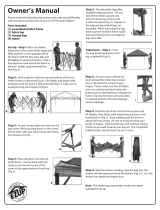
1
1
1
1
1
1
2
2
2
2
2
2
5
5
5
5
5
5
5
5
13
12
12
12
12
13
13
13
13
13
13
13
16
16
16
16
16
16
10
15
15
15
15
15
15
9
3
8
8
8
8
9
6
6
05-51331-0B 06/07/07
12'x20'x8' RoundTop
®
Frame Assembly
Please read and understand instructions completely before assembly.
www.shelterlogic.com
150 Callender Road
Watertown, CT 06795
ATTENTION:
FOR MISSING OR
REPLACEMENT PARTS
OR QUESTIONS,
PLEASE CONTACT
CUSTOMER SERVICE:
1.800.524.9970
Assembly
Reference #
1
2
3
4
5
6
7
8
9
10
11
12
13
14
15
16
Quantity
of Parts
6
6
4
8
12
3
10
16
8
2
8
4
14
24
20
12
Mfg.
Part #
10224
10225
10226
10273
2030
2031
10110
10111
10112
10205
10270
669
10210
10114
10115
800260
1.
Layout out frame parts as shown.
2.
Match up items with quantity to make sure
no parts are missing.
End Rib
End Rib
Middle Ribs
Wind Brace
Wind Brace
Cover Rails
Side
Rails
Top
Rails

Page 3
Basic Frame Assembly
STEP 1 ASSEMBLE END RAIL
Fig. 1
STEP 2 ASSEMBLE MIDDLE RIB
Fig.2
Fig.1
Fig.2
STEP 3 INSTALL SHELTERLOCK STABILZER
Fig. 3A
Fig.3A
10210
800260
01010
2030
2030
Fig.3B
2030
2030
2030
2030
Stand end rib vertically against a solid structure. Place ShelterLock
Stabilizer Block (#800260) between Cross Rail and rib using ¼" x 3" L
(#10210) bolt through the rib and stabilizer with bolt head on the
outside of the rib. Place plain end of Cross Rail (#2030) onto the bolt
and nest into the ShelterLock Stabilizer Block. Secure with nut
(#01010). Assemble opposite Side Rail in the same manner. Con-
tinue to add all ribs, ShelterLock Stabilizer Block and Side Rails in the
same manner.
Attach Wind Brace to lower end of second Middle Rib. Using ¼" x 2" L
bolt and nut attach other end of Wind Brace to middle of End Rib
using ¼" x 2" L nut and bolt. Bolt head must be on the outside of rib.
Assemble other Wind Brace in the same manner.
Fit together an end rib using the following parts:
(1) #10224 Bent Tube Swedged
(1) #10225 Bent Tube Plain and
(2) #10226 Bent Corner Leg. Using
(2) #10114 1/4" x 2" L Carriage Bolts and
(2) #1010 1/4" Nuts
Securely fasten the joints of the Corner Legs to the bends. Assemble
both end ribs.
#10114
2" Bolts
#10210
3" Bolts
Assemble middle ribs using the following parts:
(1) #10224 Bent Tube Swedged
(1) #10225 Bent Tube Plain and
(2) #10273 Middle Upright Tube
Using (2) #10114 1/4" x 2" L Carriage Bolts (1) #669 1/4" x 3" Round
Head Bolt and (3) #1010 1/4" nuts, securely fasten the joints of the egs to
the bends. Assemble all middle ribs.
#10114
2" Bolts
#669
3" Bolts
STEP 3 INSTALL WIND BRACE
Fig. 3B
10205
10205
Wind
Brace
Wind
Brace
10225
10224
10226
10226
10225
10224
10273
10273

Page 4
Install the Top Rail
OVER all Middle Ribs
UNDER First & Last Ribs
STEP 5 ATTACH & SECURE
BASE FEET- Fig. 5
STEP 4 INSTALLING TOP RAIL
Fig 4.
STEP 7 ANCHORING SHELTER
Fig. 7&8
Fig.4
Fig.5
Fig.7 Fig.8
Base Feet will either fit outside or inside the frame leg poles
(based on model). Place a base foot plate inside or outside
each of the middle leg poles, lining up the pre-drilled holes.
Insert
1
/
4
" x 2" L Bolts (#10114) through the leg and foot and
secure with
1
/
4
" nuts.
Auger Anchors On Packed or loose dirt or grass Surfaces.
1. Sink Augers into the ground at the End Rib Corner Leg inside the
shelter by turning the auger clockwise until level with the leg bends
2. Secure the anchors to the corner leg bends using the cable and camp
by looping cable around the leg bend. Secure with Clamps. (Fig 7)
3. Repeat process attaching remaining auger anchors to middle rib legs
looping cable around the upright above the foot plate (Fig 8)
Note: Anchors must be placed inside of shelter.
2031
2031
2031
1. Start with (1) Plain Cross Rail Tube (#2031)
Under the first End rib.
2. Attach another Cross Rail Tube (#2031) over the
middle ribs.
3. End with (1) Cross Rail Tube (#2031) under the
rear End Rib.
NOTE: Use the Special Round Head
1
/
4
" x 3" Bolts
(#669) for securing the top rail to the Middle Ribs
only. Use the standard
1
/
4
" x 3" Bolts (#10210) for
securing the top rail to the end ribs.
End with
(1) #2030
STEP 6 PLOTTING THE FRAME
Fig. 6
Before anchoring the shelter and putting on the cover the frame
should be plotted. These steps should be completed:
1. All ribs measure 12’ from outside of pipe to outside of
opposing pipe.
2. Total footprint of the unit should be 12' W X 20' L.
3. To square unit (Fig. 6) Install 4 stakes in ground 12' W X 20' L.
Tie a string kitty-corner to each stake. The distance from the
intersection of strings to each corner should be equal.
Fig.6
Depending on the model you have purchased, your Base Feet
will either fit onto the outside of the Leg Poles, or slide inside
the Leg Poles. After installing Base Feet Plates onto bottom
of the Middle Leg Poles, be sure to line up the pre-drilled hole
in the leg with the pre-drilled hole in the Base Foot. Insert
1/4" x 2" bolts all the way through leg and foot, to other side,
secure with nuts.
12'
12'
20'
Secure with
Bolt & Nut
Stakes

Page 5
STEP 8 SECURE THE COVER / RATCHET TITE
Fig. 10
Check and tighten Ratchets
and Cross Rail bolts monthly
to ensure the cover is tight.
Outside Corner View
Fig. 13
Fig. 10
corner leg
clamps
10115
1010
10112
Fig.11
middle leg
clamps
10115
10111
1010
Fig.12
NOTE: Bolt through clamps and cover rails for corner leg and middle leg detail.
1. Pull the cover over the frame from the side noting that the welded-in webbing should be at
the front and rear of the shelter.
2. Note- the white interior with pocket and cut outs running along the sides should face inside
and be placed near ground level.
3. ShelterLogic Logo should appear on the left front and right rear corners as indicated in
Fig 10.
4. Insert “S” hook from Ratchet Tite into the hole in the corner leg bends at each corner
5. Insert the webbing from the cover into the spindle of the ratchet and tighten on each corner.
Adjust as necessary.
6. Once cover is even, finish tightening ratchets alternating from corner to corner to ensure an
even cover tie down.
10110
Cover Rail
10110
Cover Rail
COVER TIGHTENING TIP
NOTE: ShelterLogic logo should line up on the left front and right rear corners near the top rail. If it is not legible
and positioned as above- the cover is not on the frame correctly.
IS YOUR COVER PULLED CORRECTLY ON THE FRAME?
Fig. 13
STEP 9
ATTACH & SECURE
CROSS RAILS
Fig. 11&12
1. With cover tight and even add
the cross rails and connectors on
one side of the frame by placing
Cover Rail (10110) into pockets
between the cut outs.
2. Attach the cross rails to the
frame using the 3 way and 4 way
cover rail clamps around the uprights
and fasten with
1
/
4
" x 1
5
/
8
" L bolts
(# 10115) and
1
/
4
" nuts (#1010).
3. Make sure rails are evenly
spaced and at the same level. Push
down on the connectors one at a
time and tighten bolts for optimal
tension on the cover
Warning: Serious injury to persons or property could result if cover is installed and shelter is not completed and is
left unattended. Shelter must be tied down and anchor securely until completed.
CORRECT
INCORRECT

STEP 10 ATTACH THE
PROTECTIVE BOOTS
Fig. 14
Page 6
Fig. 14
WARNING
Prior to installation, consult with all local and municipal codes regarding the installation of temporary
shelters. Choose the location of your shelter carefully. Check for overhead utility lines, tree branches or
other structures. Do NOT install near roof lines or other structures that could shed snow, ice, or excessive
run-off onto your shelter. Do NOT hang objects from the roof structure or support cables. Do NOT smoke
our use open flame devices in or around the shelter. Do NOT store flammable liquids (gasoline, kerosene,
propane, barbeque grills, fire pits, deep fryers or smokers inside the shelter. Do NOT use hard edged tools
or instruments like rakes or shovels to remove snow. This could result in punctures in the cover.
CAUTION
This product is classified as a temporary fabric shelter and is intended to protect what is stored in it
against basic environmental elements, including the effects of sun, rain, tree sap, bird and animal
excrement and light snow. It is NOT designed to hold the loads from high winds, heavy snow or ice
storms. Proper anchoring is the responsibility of the consumer. Please read and understand the
installation details and warnings prior to final and permanent installatioin. If you have any questions,
call the customer service number listed on Page 1. Any shelter that is not anchored securely and properly
has the potential to fly away. ShelterLogic cannot be responsible for any shelter that blows away. NOTE:
Your shelter’s cover can be quickly removed and stored prior to severe weather conditions. If strong
winds or severe weather is forecast in your area, we recommend that you remove the cover.
CARE & CLEANING
A tight cover will ensure longer life and performance. Inspect and retighten the ratchet tie-downs monthly
as needed. Always maintain a tight cover. Loose fabric can accelerate deterioration of the cover.
Immediately remove any accumulated snow or ice from the roof structure with a broom, mop or other
soft sided instrument. Do NOT use “protect and shine” or harsh or abrasive products to clean the fabric
cover. Mild soap and water is recommended to clean the fabric cover of your shelter.
Find the open side of the Protective Boot and open it.
Insert the foot of the Corner Leg into the Protective Boot.
When the foot is all the way in the boot insert the top edge
of the boot into the hem of the cover (Fig 14).
When complete, secure the hook & loop fastener on the
open side of the boot to close It.
WARNINGS, CAUTIONS, CARE & CLEANING
/