Page is loading ...

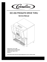
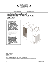
VISUAL MERCHANDISERS
COR7VM, COR12VM, COR17VM, COR23VM,
COR35VMSD, COR45VMSD, COR49VMD, COR67VMST
Service Manual
Release Date: May 24, 2005
Publication Number: 630460243SER
Revision Date: NA
Revision: A
Visit the IMI Cornelius web site at www.cornelius.com
for all your Literature needs.
®

SERVICE MANUAL
The products, technical information, and instructions contained in this manual are subject
to change without notice. These instructions are not intended to cover all details or varia-
tions of the equipment, nor to provide for every possible contingency in the installation,
operation or maintenance of this equipment. This manual assumes that the person(s)
working on the equipment have been trained and are skilled in working with electrical,
plumbing, pneumatic, and mechanical equipment. It is assumed that appropriate safety
precautions are taken and that all local safety and construction requirements are being
met, in addition to the information contained in this manual.
To inquire about current revisions of this and other documentation or for assistance with
any Cornelius product contact:
www.cornelius.com
800-238-3600
Trademarks and copyrights:
Aurora, Cornelius, Decade, Hydro Boost, Sitco, Spirit, UF-1, Vanguard, Venture, Olym-
pus, and Vista are registered trademarks of IMI Cornelius Inc.
Optifill trademark is pending.
This document contains proprietary information and it may not be
reproduced in any way without permission from Cornelius.
Printed in U.S.A.
Copyright © 2005, All Rights Reserved, IMI Cornelius, Inc.

Visual Merchandiser Service Manual
© 2005, IMI Cornelius Inc. - i - Publication Number: 630460243SER
TABLE OF CONTENTS
Features of the Unit . . . . . . . . . . . . . . . . . . . . . . . . . . . . . . . . . . . . . . . . . . . . . . . . . . 1
Cleaning and Preventive Maintenance . . . . . . . . . . . . . . . . . . . . . . . . . . . . . . . . . . . 1
Fluorescent Lamp and Ballast Replacement . . . . . . . . . . . . . . . . . . . . . . . . . . . . . . 2
To remove the motor cover . . . . . . . . . . . . . . . . . . . . . . . . . . . . . . . . . . . . . . . . . 2
Ballast Replacement . . . . . . . . . . . . . . . . . . . . . . . . . . . . . . . . . . . . . . . . . . . . . . . . . 3
Required tool . . . . . . . . . . . . . . . . . . . . . . . . . . . . . . . . . . . . . . . . . . . . . . . . . . . . 3
To remove the ballast . . . . . . . . . . . . . . . . . . . . . . . . . . . . . . . . . . . . . . . . . . . . . 3
To replace the fluorescent lamp . . . . . . . . . . . . . . . . . . . . . . . . . . . . . . . . . . . . . 4
Temperature Control Replacement . . . . . . . . . . . . . . . . . . . . . . . . . . . . . . . . . . . . . . 6
Required tool . . . . . . . . . . . . . . . . . . . . . . . . . . . . . . . . . . . . . . . . . . . . . . . . . . . . 6
To remove the temperature control . . . . . . . . . . . . . . . . . . . . . . . . . . . . . . . . . . . 6
Evaporator Fan Motor Replacement . . . . . . . . . . . . . . . . . . . . . . . . . . . . . . . . . . . . . 9
Required tools . . . . . . . . . . . . . . . . . . . . . . . . . . . . . . . . . . . . . . . . . . . . . . . . . . . 9
To disconnect the evaporator fan motor electrical terminals . . . . . . . . . . . . . . . 10
To remove the evaporator fan motor . . . . . . . . . . . . . . . . . . . . . . . . . . . . . . . . . 11
Condensing Unit Fan Motor Replacement . . . . . . . . . . . . . . . . . . . . . . . . . . . . . . . 13
Required tools . . . . . . . . . . . . . . . . . . . . . . . . . . . . . . . . . . . . . . . . . . . . . . . . . . 13
To remove the motor cover . . . . . . . . . . . . . . . . . . . . . . . . . . . . . . . . . . . . . . . . 13
To pull out the condensing unit . . . . . . . . . . . . . . . . . . . . . . . . . . . . . . . . . . . . . 14
To replace the condensing unit fan motor . . . . . . . . . . . . . . . . . . . . . . . . . . . . . 15
Starting Relay, Overload Protector, and Start Capacitor Replacement . . . . . . . . . 17
Required tool . . . . . . . . . . . . . . . . . . . . . . . . . . . . . . . . . . . . . . . . . . . . . . . . . . . 17
To remove the motor cover . . . . . . . . . . . . . . . . . . . . . . . . . . . . . . . . . . . . . . . . 17
To pull out the condensing unit . . . . . . . . . . . . . . . . . . . . . . . . . . . . . . . . . . . . . 18
To remove the electrical box . . . . . . . . . . . . . . . . . . . . . . . . . . . . . . . . . . . . . . . 20
To replace the relay . . . . . . . . . . . . . . . . . . . . . . . . . . . . . . . . . . . . . . . . . . . . . 21
To replace the overload protector . . . . . . . . . . . . . . . . . . . . . . . . . . . . . . . . . . . 22
To replace the starting capacitor . . . . . . . . . . . . . . . . . . . . . . . . . . . . . . . . . . . . 22
To install the electrical box . . . . . . . . . . . . . . . . . . . . . . . . . . . . . . . . . . . . . . . . 23
Door and Spring Hinge System . . . . . . . . . . . . . . . . . . . . . . . . . . . . . . . . . . . . . . . . 25
Required tools . . . . . . . . . . . . . . . . . . . . . . . . . . . . . . . . . . . . . . . . . . . . . . . . . . 25
To remove the motor cover . . . . . . . . . . . . . . . . . . . . . . . . . . . . . . . . . . . . . . . . 25
To remove the door . . . . . . . . . . . . . . . . . . . . . . . . . . . . . . . . . . . . . . . . . . . . . . 26
To install the door . . . . . . . . . . . . . . . . . . . . . . . . . . . . . . . . . . . . . . . . . . . . . . . 29
To assemble spring hinge components . . . . . . . . . . . . . . . . . . . . . . . . . . . . . . 34
Glass Door Pane Replacement . . . . . . . . . . . . . . . . . . . . . . . . . . . . . . . . . . . . . . . . 39
To remove the motor cover and door . . . . . . . . . . . . . . . . . . . . . . . . . . . . . . . . 39
Required tools . . . . . . . . . . . . . . . . . . . . . . . . . . . . . . . . . . . . . . . . . . . . . . . . . . 39
To remove the glass door pane . . . . . . . . . . . . . . . . . . . . . . . . . . . . . . . . . . . . 39
To install the door . . . . . . . . . . . . . . . . . . . . . . . . . . . . . . . . . . . . . . . . . . . . . . . 42
Refrigeration System . . . . . . . . . . . . . . . . . . . . . . . . . . . . . . . . . . . . . . . . . . . . . . . . 42
Compressor . . . . . . . . . . . . . . . . . . . . . . . . . . . . . . . . . . . . . . . . . . . . . . . . . . . . 42
Starter relay . . . . . . . . . . . . . . . . . . . . . . . . . . . . . . . . . . . . . . . . . . . . . . . . . . . . 42

Visual Merchandiser Service Manual
Publication Number: 630460243SER - ii - © 2005, IMI Cornelius Inc.
Thermal protector . . . . . . . . . . . . . . . . . . . . . . . . . . . . . . . . . . . . . . . . . . . . . . . 42
Condenser . . . . . . . . . . . . . . . . . . . . . . . . . . . . . . . . . . . . . . . . . . . . . . . . . . . . . 42
Condenser fan motor . . . . . . . . . . . . . . . . . . . . . . . . . . . . . . . . . . . . . . . . . . . . 43
Evaporator . . . . . . . . . . . . . . . . . . . . . . . . . . . . . . . . . . . . . . . . . . . . . . . . . . . . . 43
Evaporator fan motor . . . . . . . . . . . . . . . . . . . . . . . . . . . . . . . . . . . . . . . . . . . . 43
Capillary tube . . . . . . . . . . . . . . . . . . . . . . . . . . . . . . . . . . . . . . . . . . . . . . . . . . 43
Drier . . . . . . . . . . . . . . . . . . . . . . . . . . . . . . . . . . . . . . . . . . . . . . . . . . . . . . . . . 43
Accumulator . . . . . . . . . . . . . . . . . . . . . . . . . . . . . . . . . . . . . . . . . . . . . . . . . . . 43
Temperature control . . . . . . . . . . . . . . . . . . . . . . . . . . . . . . . . . . . . . . . . . . . . . 43
Cooling cabinet . . . . . . . . . . . . . . . . . . . . . . . . . . . . . . . . . . . . . . . . . . . . . . . . . 44
The Refrigeration Cycle . . . . . . . . . . . . . . . . . . . . . . . . . . . . . . . . . . . . . . . . . . . . . 44
Wiring Diagram 115 V/60 Hz/1 Phase . . . . . . . . . . . . . . . . . . . . . . . . . . . . . . . . . . 45
Troubleshooting . . . . . . . . . . . . . . . . . . . . . . . . . . . . . . . . . . . . . . . . . . . . . . . . . . . 46
Possible causes and solutions . . . . . . . . . . . . . . . . . . . . . . . . . . . . . . . . . . . . . 46

Visual Merchandiser Service Manual
© 2005, IMI Cornelius Inc. - 1 - Publication Number: 630460243SER
FEATURES OF THE UNIT
CLEANING AND PREVENTIVE MAINTENANCE
Weekly or sooner, as required:
1. Disconnect the power source before cleaning. Remove all products and place in a proper cooler.
2. Clean the interior and exterior with a mild soap or detergent solution and then rinse with a warm
baking soda solution (one cup of baking soda to one gallon of warm water). Dry the interior
completely before replacing products.
3. Clean the condenser unit periodically by vacuuming the unit compartment, especially the
condenser unit coil (it looks like a small auto radiator). If the condenser coil has accumulated dirt
and grease (possible in heavy traffic areas or a kitchen), use a strong cleaning solution. If you find
any oil in the condensing unit compartment, call a qualified service person immediately.
4. Empty out and clean the drain pan located next to the condensing unit as required. Check regularly
for excessive water accumulation.
5. Plug in the cabinet and wait until the proper temperature is achieved before reloading the cabinet
with product.
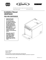
FIGURE 1
Fluorescent interior light
Strong body with 1 3/4”
thick walls, injected with
CFC-free polyurethane
foam
Forced-air evaporator
for quick temperature
pull down
NSF compliant
interior cabinet
Heavy duty R-134a
condensing unit with zero
maintenance condenser
Heavy duty hinges
Double-pane low-e glass
door for high ambient
conditions
Durable PVC frame
Exterior cabinet made of
galvanized, pre-painted
steel, with baked polyester
paint
Reinforced heavy-duty
shelves
Reinforced, 16-gauge,
galvanized steel base

Visual Merchandiser Service Manual
Publication Number: 630460243SER - 2 - © 2005, IMI Cornelius Inc.
FLUORESCENT LAMP AND BALLAST REPLACEMENT
If any electrical problems arise, a wiring diagram is included with each cabinet to aid in tracing the source
of trouble and making the necessary repairs.
To remove the motor cover
3. Remove the condensing unit motor cover by pulling it up and out.
CAUTION - Make sure the power supply is
turned off before making any electrical
repairs.
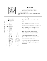
1. Open the door.
FIGURE 2
2. Use a #2 Phillips screwdriver to remove the flat-head screw
holding condensing the unit motor cover.
FIGURE 3
FIGURE 4

Visual Merchandiser Service Manual
© 2005, IMI Cornelius Inc. - 3 - Publication Number: 630460243SER
BALLAST REPLACEMENT
Required tool
• one #2 Phillips screwdriver with a 4” long blade
To remove the ballast
1. Push down with your fingers on the plastic tabs that hold the male and female connectors in
position. Then pull out the male connector (connected to the ballast).
2. Use a Phillips screwdriver to remove the single screw holding the ballast to the metal bracket. The
ballast sits on a metal bracket to make replacement easier.
FIGURE 5
FIGURE 6

Visual Merchandiser Service Manual
Publication Number: 630460243SER - 4 - © 2005, IMI Cornelius Inc.
3. To remove the ballast, lift the ballast wires over the metal bracket which holds the back end of the
ballast.
4. To reinstall a new ballast reverse steps 1 through 3.
To replace the fluorescent lamp
FIGURE 7
1. Pull one end of the lamp holder base half way out.
FIGURE 8
2. Pull the other end of the lamp holder base half way out.
FIGURE 9

Visual Merchandiser Service Manual
© 2005, IMI Cornelius Inc. - 5 - Publication Number: 630460243SER
4. Remove the lamp holder bases from each end of the lamp.
6. To install a new lamp, reverse steps 1 through 5.
3. Once the two bases have been pulled half way out, use both
hands to pull out the entire lamp assembly
FIGURE 10
FIGURE 11
5. Remove the plastic cover from the lamp. Now you can
replace the lamp.
FIGURE 12

Visual Merchandiser Service Manual
Publication Number: 630460243SER - 6 - © 2005, IMI Cornelius Inc.
TEMPERATURE CONTROL REPLACEMENT
If any electrical problems arise, a wiring diagram is included with each cabinet to aid in tracing the source
of trouble and making the necessary repairs.
Required tool
• one #2 Phillips screwdriver with a 4” long blade
To remove the temperature control
With the temperature control mounting plate removed from the baffle, you can see the thermostat,
light, and fan motor connectors.
CAUTION - Make sure the power supply is
turned off before making any electrical
repairs.
1. Remove the two Phillips head screws that hold the
temperature control mounting plate (located on the baffle).
FIGURE 13
FIGURE 14
Evaporator fan motor connections
Fluorescent lamp connections
Temperature control connections

Visual Merchandiser Service Manual
© 2005, IMI Cornelius Inc. - 7 - Publication Number: 630460243SER
3. Carefully pull the bulb sensor out of the temperature control well. There is a patch of permagum at
the opening of the well which seals the bulb sensor from humidity.
2. Disconnect the electrical connections from the temperature
control.
FIGURE 15
FIGURE 16
Temperature control sensing bulb
Temperature control well

Visual Merchandiser Service Manual
Publication Number: 630460243SER - 8 - © 2005, IMI Cornelius Inc.
The bulb sensor has a slight curve to make a tight fit inside
the temperature control well.
FIGURE 17
4. Remove the temperature control knob by pulling it outward.
FIGURE 18
5. Use a Phillips screwdriver to remove the two Phillips head
screws the hold the temperature control to its mounting
plate.
FIGURE 19

Visual Merchandiser Service Manual
© 2005, IMI Cornelius Inc. - 9 - Publication Number: 630460243SER
EVAPORATOR FAN MOTOR REPLACEMENT
If any electrical problems arise, a wiring diagram is included with each cabinet to aid in tracing the source
of trouble and making the necessary repairs.
Required tools
To replace the evaporator fan motor, you need:
• one #2 Phillips screwdriver with 4” blade
• one side-cutting pliers
• one 1/4” socket screwdriver
6. With the two Phillips head screws removed, you can now
install a new temperature control by reversing steps 1
through 5.
FIGURE 20
CAUTION - Make sure the power supply is
turned off before making any electrical
repairs.

Visual Merchandiser Service Manual
Publication Number: 630460243SER - 10 - © 2005, IMI Cornelius Inc.
To disconnect the evaporator fan motor electrical terminals
With the temperature control mounting plate removed from the baffle, you can see the thermostat, light,
and fan motor connectors.
1. Remove the two Phillips head screws that hold the
temperature control mounting plate (located on the baffle).
FIGURE 21
FIGURE 22
2. Disconnect the fan motor electrical connector.
FIGURE 23
Evaporator fan motor connections
Fluorescent lamp connections
Temperature control connections

Visual Merchandiser Service Manual
© 2005, IMI Cornelius Inc. - 11 - Publication Number: 630460243SER
3. Remove the rubber grommet, located in the plastic bushing near at the right air diffuser.
To remove the evaporator fan motor
FIGURE 24
1. Use a Phillips screwdriver to remove the four screws holding
the evaporator fan grill at the baffle.
FIGURE 25
2. Remove the fan blade. Use the side-cutting pliers to
unscrew the nut-type washer that holds the fan motor in
place.
FIGURE 26

Visual Merchandiser Service Manual
Publication Number: 630460243SER - 12 - © 2005, IMI Cornelius Inc.
3. Pass the electrical wire of the motor through the plastic bushing on the air diffuser.
6. Replace the fan motor with another of the same model. Reinstall the fan motor by reversing steps 1
through 5.
FIGURE 27
4. Use a Phillips screwdriver to remove the four screws holding the base of the fan motor to the top of
the internal cabinet.
FIGURE 28
5. Use a 1/4” socket screwdriver to remove the three socket head screws holding the fan motor to its
base.
FIGURE 29
Plastic bushing on the air diffuser
Four Phillips head screws
Three socket head screws

Visual Merchandiser Service Manual
© 2005, IMI Cornelius Inc. - 13 - Publication Number: 630460243SER
CONDENSING UNIT FAN MOTOR REPLACEMENT
If any electrical problems arise, a wiring diagram is included with each cabinet to aid in tracing the source
of trouble and making the necessary repairs.
Required tools
The following tools are required to repair the spring hinge system or assemble a new door:
• one Phillips #2 screwdriver with 4” blade
• one 3/8” open end or box end wrench
• one 7/16” open end or box end wrench
• one adjustable wrench, 4” or 6”
• one measuring tape
To remove the motor cover
CAUTION - Make sure the power supply is
turned off before making any electrical
repairs.
1. Open the door.
FIGURE 30
2. Use a #2 Phillips screwdriver to remove the flat-head screw
holding condensing the unit motor cover.
FIGURE 31

Visual Merchandiser Service Manual
Publication Number: 630460243SER - 14 - © 2005, IMI Cornelius Inc.
3. Remove the condensing unit motor cover by pulling it up and out.
To pull out the condensing unit
1. Use a 1/2” open or box end wrench to remove the bolts that hold the rails that support the
condensing unit.
FIGURE 32
FIGURE 33
2. Slowly push the condensing unit from the rear of the cabinet. Be sure the suction line and the
capillary tubing do not break.
FIGURE 34

Visual Merchandiser Service Manual
© 2005, IMI Cornelius Inc. - 15 - Publication Number: 630460243SER
3. Pull the condensing unit about 13 inches from the base of the cabinet to provide access to the
condensing unit fan motor, relay, overload protector, and capacitor.
To replace the condensing unit fan motor
2. Disconnect the fan motor electrical connectors.
FIGURE 35
1. Untie the fan motor electrical wire.
FIGURE 36
FIGURE 37

Visual Merchandiser Service Manual
Publication Number: 630460243SER - 16 - © 2005, IMI Cornelius Inc.
6. Use the side cutting pliers to remove the fan blade.
3. Use a 7/16” open end or box end wrench to remove the four
nuts and bolts that hold the base of the fan motor to the rails
of the condensing unit.
FIGURE 38
4. Tilt the fan motor from one corner in the direction of the
arrow to remove the fan motor from the condenser shroud.
FIGURE 39
5. Pull the fan motor out in the direction of the arrow.
FIGURE 40
FIGURE 41
/