Crestron QM-FTMCSC-NB Installation guide
- Category
- Numeric keypads
- Type
- Installation guide
This manual is also suitable for

Crestron QM-FTMCSC
FlipTop Media Center
with Storage Compartment
Operations & Installation Guide

This document was prepared and written by the Technical Documentation department at:
Crestron Electronics, Inc.
15 Volvo Drive
Rockleigh, NJ 07647
1-888-CRESTRON
All brand names, product names and trademarks are the property of their respective owners.
©2007 Crestron Electronics, Inc.

Crestron QM-FTMCSC FlipTop Media Center with Storage Compartment
Contents
FlipTop Media Center with Storage Compartment: QM-FTMCSC 1
Introduction ...............................................................................................................................1
Features and Functions................................................................................................ 1
Internal Block Diagram ............................................................................................... 4
Specifications ..............................................................................................................5
Physical Description....................................................................................................7
Industry Compliance ................................................................................................. 14
Setup ........................................................................................................................................15
Network Wiring.........................................................................................................15
QuickMedia Wiring................................................................................................... 15
Identity Code ............................................................................................................. 16
Installation................................................................................................................. 17
Hardware Hookup .....................................................................................................22
Configuration Software ...........................................................................................................24
Earliest Version Software Requirements for the PC ................................................. 24
Configuring with SystemBuilder...............................................................................24
Configuring with SIMPL Windows .......................................................................... 25
Example Program...................................................................................................... 27
Adjusting the QM-FTMCSC Microphone Inputs...................................................... 27
Uploading and Upgrading........................................................................................................ 30
Establishing Communication.....................................................................................30
Programs and Firmware ............................................................................................30
Program Checks ........................................................................................................ 31
Problem Solving ......................................................................................................................32
Troubleshooting......................................................................................................... 32
Check Network Wiring..............................................................................................33
Reference Documents................................................................................................ 34
Further Inquiries ........................................................................................................34
Future Updates ..........................................................................................................35
Appendix A: International Receptacles ..................................................................................36
Appendix B: QuickMedia Installation and Compensation ..................................................... 37
Installation Notes....................................................................................................... 37
Compensation............................................................................................................ 37
Compatibility Charts ................................................................................................. 39
Return and Warranty Policies .................................................................................................. 41
Merchandise Returns / Repair Service ...................................................................... 41
CRESTRON Limited Warranty.................................................................................41
Operations & Installation Guide – DOC. 6307B Contents • i


Crestron QM-FTMCSC FlipTop Media Center with Storage Compartment
FlipTop Media Center with
Storage Compartment: QM-FTMCSC
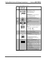
Introduction
Features and Functions
The QM-FTMCSC FlipTop Media Center is part of the Crestron MediaManager™
line of network devices, room control systems and signal routing solutions. It is
available in six different models (hereinafter referred to as QM-FTMCSC except
where noted).
Models
DESCRIPTION MODEL NUMBER COLOR
QM-FTMCSC-B Black Domestic Models
with Keypad
QM-FTMCSC-BALUM Brushed Aluminum
QM-FTMCSC-NB-B Black Domestic Models
without Keypad
QM-FTMCSC-NB-BALUM Brushed Aluminum
QMI-FTMCSC-B Black International Models
with Keypad
QMI-FTMCSC-BALUM Brushed Aluminum
Functional Summary
• Stylish flush-mount FlipTop housing
• Built-in engravable* keypad with 10 to 20 buttons and LEDs and dual
bargraphs (keypad models only)
• Composite, S-video, RGB/component and stereo audio inputs
• Signal sensing for RGB, component, composite and S-video
• 3 x 1 video switch (one composite, one S-video and one RGBHV
connector)
• 3 x 1 audio switch (two mic connectors, two for S-video audio
and two for composite video audio) with audio breakaway
• One AC power pass through (power cord included)
• Two mic inputs with phantom power (on the bottom)
• One QuickMedia RJ-45 connector (on the bottom)
• Two Cresnet
®
connectors (on the bottom)
• Computer connections on the underside include cables that feed
through the box and cable management plate
* As an option, custom-engraved buttons can be designed and obtained by using the Crestron Engraver
software. Version 2.3.3 and Crestron Database 16.3.4 or later are available from the Crestron website
(http://www.crestron.com
).
Operations & Installation Guide – DOC. 6307B FlipTop Media Center with Storage Compartment: QM-FTMCSC • 1

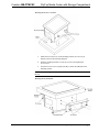
FlipTop Media Center with Storage Compartment Crestron QM-FTMCSC
FlipTop Housing
Handsomely finished in either black anodized or brushed aluminum, the
QM-FTMCSC mounts flush in any tabletop surface for a clean, professional
appearance. The sleek design of the “FlipTop” lid features an integrated keypad
(keypad models only) to provide programmable pushbutton control at every interface
location. Wiring for the QM-FTMCSC is extremely simple requiring just a single
CresCAT™-QM cable (sold separately).
Multimedia Interface
Individual inputs are provided for composite, S-video and RGB/component signals,
each with corresponding stereo audio, to accept connections from portable AV
devices and computers. For complete connectivity, the QM-FTMCSC also includes
an AC power receptacle.
Cable Storage Compartment
Connectivity for computer signals is facilitated using easy pull-out RGB and audio
cables (included), which attach to inputs hidden beneath the table surface and stow
neatly within the FlipTop compartment when not in use. Excess cable simply drops
out of sight below the box through grommeted holes provided in the bottom plate.
Network connectivity is easily included using any third-party LAN cable.
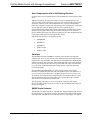
Integrated Keypad (optional)
The QM-FTMCSC can be ordered with or without a keypad. This customizable
keypad provides 10 to 20 programmable pushbuttons for control of AV, lighting and
other functions. All button caps are engravable and include LED feedback indicators.
Two LED bargraphs are also provided to display level settings and other parameters.
To prevent accidental button presses, the keypad is automatically disabled whenever
the lid is not fully opened.
AV Switcher and Mic Preamp
The built-in 3 x 1 switcher includes audio breakaway to allow the three program
audio inputs to be switched independent of the video and RGB inputs. Additionally,
two gated microphone inputs are included via terminal block connectors located
below the table surface. Both dynamic and condenser type microphones are
supported with software switchable 48V phantom power available at both
microphone inputs. Balanced or unbalanced line level sources such as wireless
microphones can also be accommodated. Input gain and gating controls for each
microphone/line input are fully adjustable at setup and can also be controlled in real
time from a keypad or touchpanel.
QuickMedia™ Transport
Using Crestron’s revolutionary QuickMedia (QM) transport, all input signals are
transmitted from the QM-FTMCSC to any QuickMedia Receiver or Distribution
Center over a single inexpensive CAT5e type cable. Computer resolutions up to
1920 x 1200 pixels at 60 Hz are supported over cable runs up to 450 feet (137
meters). Audio signals are transmitted digitally with high performance 24-bit
resolution. QuickMedia dramatically simplifies system design and installation,
affording a higher level of performance at a lower overall cost.
NOTE: For QuickMedia wiring use CresCAT-QM, CresCAT-IM or quality
Cat5e/CAT6 cable. The maximum aggregate cable length and delay skew between
any QM transmitter (origination point) and QM receiver (endpoint) is 450 feet (137
2 • FlipTop Data Center with Storage Compartment: QM-FTMCSC Operations & Installation Guide – DOC. 6307B

Crestron QM-FTMCSC FlipTop Media Center with Storage Compartment
meters) and 22 ns. A maximum of two QM midpoint devices may be inserted in a
given QM signal path (exceptions apply, refer to each respective product manual for
full details).
MediaManager™ System Integration
Whether using just one FlipTop box or several, complete system operation can be
made transparent to the end user with all signal routing occurring smoothly under the
command of the MediaManager control system. Built-in video sensing on every
video/RGB input can be utilized to trigger automatic input selection and power
control. Complete MediaManager systems are easy to design, program and adjust
from start to finish using Crestron SystemBuilder™ software.
Cresnet
®
Cresnet is the communications backbone for many Crestron touchpanels, keypads,
lighting controls and other devices. The Cresnet bus is a simple, yet flexible 4-wire
network that provides rock-solid bidirectional communication and power for
numerous Cresnet devices.
Operations & Installation Guide – DOC. 6307B FlipTop Media Center with Storage Compartment: QM-FTMCSC • 3

FlipTop Media Center with Storage Compartment Crestron QM-FTMCSC
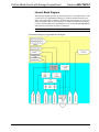
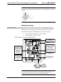
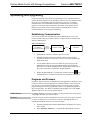
Internal Block Diagram
The following diagram represents the interfacing abilities of the QM-FTMCSC. This
Cresnet device uses QuickMedia technology to facilitate simplified connection of
audio, video and computer equipment. All media and control signals are routed via a
single QuickMedia cable for easy installation. A complete integrated room solution
is created with the addition of a QuickMedia receiver (such as the QM-RMCRX-BA,
sold separately) and optional keypads or touchpanels.
NOTE: The QM-FTMCSC is compatible with 2-Series control systems only.
Internal Block Diagram of the QM-FTMCSC (with Keypad)
4 • FlipTop Data Center with Storage Compartment: QM-FTMCSC Operations & Installation Guide – DOC. 6307B

Crestron QM-FTMCSC FlipTop Media Center with Storage Compartment
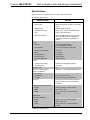
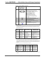
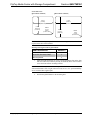
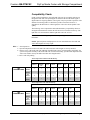
Specifications
Specifications for the QM-FTMCSC are listed in the following table.
QM-FTMCSC Specifications
SPECIFICATION DETAILS
RGB/Video
Signal Types
RGB and composite, S-video or component
video
1
RGB Formats RGBHV, RGBS or RG
s
B
Video/HDTV Formats NTSC or PAL, HDTV up to 1080i/1080p
1
Gain 0 dB (75 ohm termination)
Maximum Resolution
1920 x 1200 @ 60 Hz (at unity gain) with
maximum cable length of 450 feet (137
meters) and maximum compensation at
receiver
Audio
Features
3 x 1 stereo audio switcher,
2-channel gated mic preamp
Mic Input Gain 0 to 100% (40 dB range) plus mute
Gate Level (Threshold) 0 to 100%
Attack 0 to 100 ms
Decay (Release) 0 to 5000 ms
A-D Conversion 24-bit, 48 kHz
Frequency Response 20 Hz to 20 kHz
Power
Cresnet Power Usage 8 Watts (0.33 Amp @ 24 Volts DC)
Heat Dissipation 27 BTU/Hr
Default Net ID 0A
Minimum 2-Series Control
System Update File
2, 3
Version 3.137 (for QM-RMCRX-BA) or later
Environmental
Temperature 41° to 104°F (5° to 40°C)
Humidity 10% to 90% RH (non-condensing)
Enclosure
Black painted metal with black anodized or
brushed aluminum cover; flush tabletop
mountable
Dimensions (Domestic Models)
Height 5.39 in (13.69 cm) – with lid closed
Width 6.75 in (17.14 cm)
Depth
5.71 in (14.50 cm) – without mounting
brackets
Dimensions
(International Models)
Height 5.58 in (14.17 cm) – with lid closed
Width 8.50 in (21.58 cm)
Depth
6.67 in (16.95 cm) – without mounting
brackets
(Continued on following page)
Operations & Installation Guide – DOC. 6307B FlipTop Media Center with Storage Compartment: QM-FTMCSC • 5

FlipTop Media Center with Storage Compartment Crestron QM-FTMCSC
QM-FTMCSC Specifications (Continued)
SPECIFICATION DETAILS
Weight (Domestic Models) 4.05 lbs (1.84 kg)
Weight (International Models) 4.80 lbs (2.18 kg)
Available Models (Domestic)
QM-FTMCSC-B
QuickMedia FlipTop Media Center with
Keypad, Black Anodized
QM-FTMCSC-BALUM
QuickMedia FlipTop Media Center with
Keypad, Brushed Aluminum
QM-FTMCSC-NB-B
QuickMedia FlipTop Media Center,
no Keypad, Black Anodized
QM-FTMCSC-NB-BALUM
QuickMedia FlipTop Media Center,
no Keypad, Brushed Aluminum
Available Models (International)
QMI-FTMCSC-B
QuickMedia FlipTop Media Center with
Keypad, Black Anodized
QMI-FTMCSC-BALUM
QuickMedia FlipTop Media Center with
Keypad, Brushed Aluminum
Available Accessories
FT-BTNB-L (1) Large engravable button cap
4
FT-BTNB-S (2) Small engravable button caps
4
International Adaptors for
QMI-FTMCSC models
Refer to “Appendix A: International
Receptacles” on page 36.
1. Component video or HDTV may require a suitable VGA-to-component adaptor or breakout cable (not
included).
2. The latest software versions can be obtained from the Crestron website. Refer to the NOTE following
these footnotes.
3. Crestron 2-Series control systems include the AV2 and PRO2. Consult the latest Crestron Product
Catalog for a complete list of 2-Series control systems.
4. Keypad models only.
NOTE: Crestron software and any files on the website are for authorized Crestron
dealers and Crestron Authorized Independent Programmers (CAIP) only. New users
may be required to register to obtain access to certain areas of the site (including the
FTP site).
6 • FlipTop Data Center with Storage Compartment: QM-FTMCSC Operations & Installation Guide – DOC. 6307B

Crestron QM-FTMCSC FlipTop Media Center with Storage Compartment
Physical Description
This section provides information on the connections, controls and indicators
available on your QM-FTMCSC.
QM-FTMCSC Physical View (Top Open) QMI-FTMCSC Physical View (Top Open)
QM-FTMCSC Overall Dimensions (Top View) QMI-FTMCSC Overall Dimensions (Top View)
5.08 in
(12.89 cm)
6.75 in
(17.14 cm)
5.71 in
(14.50 cm)
6.83 in
(17.34 cm)
8.50 in
(21.58 cm)
6.67 in
(16.95 cm)
Operations & Installation Guide – DOC. 6307B FlipTop Media Center with Storage Compartment: QM-FTMCSC • 7

FlipTop Media Center with Storage Compartment Crestron QM-FTMCSC
QM-FTMCSC-NB (Top View)
NOTE: The physical dimensions of the NB models are identical to the models with
keypad.
QM-FTMCSC Overall Dimensions (Front View) QMI-FTMCSC Overall Dimensions (Front View)
5.21 in
(13.24 cm)
6.25 in
(15.86 cm)
7.04 in
(17.88 cm)
8.00 in
(20.31 cm)
8 • FlipTop Data Center with Storage Compartment: QM-FTMCSC Operations & Installation Guide – DOC. 6307B

Crestron QM-FTMCSC FlipTop Media Center with Storage Compartment
QM-FTMCSC (Bottom View) QMI-FTMCSC (Bottom View)
QM-FTMCSC Overall Dimensions (Rear View) QMI-FTMCSC Overall Dimensions (Rear View)
(13.69 cm)
Operations & Installation Guide – DOC. 6307B FlipTop Media Center with Storage Compartment: QM-FTMCSC • 9

FlipTop Media Center with Storage Compartment Crestron QM-FTMCSC
QM-FTMCSC Overall Dimensions (Side View) QMI-FTMCSC Overall Dimensions (Side View)
QM-FTMCSC Connectors, Controls & Indicators
(Top View)
QM-FTMCSC Connectors, Controls & Indicators
(Bottom View)
5
6 7
4
2
3
1
1413121110
9
8
15
10 • FlipTop Data Center with Storage Compartment: QM-FTMCSC Operations & Installation Guide – DOC. 6307B

Crestron QM-FTMCSC FlipTop Media Center with Storage Compartment
Connectors, Controls & Indicators
#
CONNECTORS
1
,
CONTROLS &
INDICATORS
DESCRIPTION
1 KEYPAD
2
Programmable keypad allowing variable
combinations of large and small engravable
buttons, 10 minimum (all large) to 20
maximum (all small); ships with 10 large
buttons (small buttons and engraving sold
separately)
(1) red LED per button, programmable
2 PWR LED
2
(1) green LED, indicates 24 Volts DC power
supplied from Cresnet control network
3 NET LED
2
(1) yellow LED, indicates communication with
Cresnet system
4 BARGRAPHS
2
(2) red 8-segment LED bargraphs,
programmable
5
(QM)
125V
(1) grounded AC socket, AC power pass-
through outlet
Maximum load: 10 Amps @ 125 Volts AC,
50/60 Hz
5
(QMI)
MAX 250V
(1) grounded AC socket, AC power pass-
through outlet
Specify socket type: PWR-AU-B
(Australia/China), PWR-EU-B (Europe
“Schuko”), PWR-FR-B (France), PWR-IT-B
(Italy) or PWR-UK-B (UK)
Maximum load: 10 Amps @ 250 Volts AC,
50/60 Hz
6
S-VIDEO
12
34
S-VIDEO
LR
(1) 4-pin mini DIN female, S-video (Y/C)
input
Input impedance: 75 ohms
Maximum input: level: 1 V
p-p
Signal sensing on Y
S-video DIN connector pin assignments
PIN DESCRIPTION
1 Luminance Ground
2 Chrominance Ground
3 Luminance
4 Chrominance
AUDIO (S-VIDEO)
(2) RCA female
Unbalanced stereo line level audio input
Input impedance: 10k ohms
Maximum input level: 2 V
rms
(Continued on following page)
Operations & Installation Guide – DOC. 6307B FlipTop Media Center with Storage Compartment: QM-FTMCSC • 11

FlipTop Media Center with Storage Compartment Crestron QM-FTMCSC
Connectors, Controls & Indicators (Continued)
#
CONNECTORS
1
,
CONTROLS &
INDICATORS
DESCRIPTION
7
VIDEO
VIDEO
LR
(1) RCA female, composite video input
Input impedance: 75 ohms
Maximum input level: 1 V
p-p
Includes signal sensing
AUDIO (VIDEO)
(2) RCA female
Unbalanced stereo line level audio input
Input impedance: 10k ohms
Maximum input level: 2 V
rms
8
(QM)
125 V
(1) 9 foot grounded AC line cord
Passes through to front panel AC power
outlet
8
(QMI)
MAX 250 V
(1) IEC socket
Passes through to front panel AC power
outlet
9
NET
(2) four-position terminal block connectors for
data and power. Connects to Cresnet control
network.
Pin 1 (24) Power (24 Volts DC)
Pin 2 (Y) Data
Pin 3 (Z) Data
Pin 4 (G) Ground
10
SETUP LED &
BUTTON
(1) red LED and miniature pushbutton, used
for touch-settable ID (TSID)
Used for setting network ID during initial
configuration or when the device is being
added/replaced.
11
QM
3
8
1
(1) 8-wire RJ-45 female, QuickMedia output
port
Connects to QM input port of any
QuickMedia device via CresCAT-QM or
CresCAT-IM cable
4
12
MIC/LINE (1 – 2)
G
-+-
+
(2) 5-pin 3.5 mm detachable terminal blocks
Balanced microphone/line inputs
Balanced mic input level: -60 to - 20 dBV
nominal
Balanced line input level: -28 to + 12 dBV;
4 V
rms
maximum
Unbalanced line input level: -34 to + 6 dBV;
2 V
rms
maximum
Mic input impedance: 10k ohms, accepts 60
to 600 ohm source
Line input impedance: 22k ohms balanced,
11k ohms unbalanced
Phantom power: 10 mA (total) @ 48 Volts
DC, software enabled to both MIC inputs
(Continued on following page)
12 • FlipTop Data Center with Storage Compartment: QM-FTMCSC Operations & Installation Guide – DOC. 6307B

Crestron QM-FTMCSC FlipTop Media Center with Storage Compartment
Connectors, Controls & Indicators (Continued)
#
CONNECTORS
1
,
CONTROLS &
INDICATORS
DESCRIPTION
13
COMPUTER
5
Pin 1
Pin 6
Pin 15
(1) DB15HD female
RGB(VGA)/component video
6
input
Formats: RGBHV, RGBS, RG
s
B, YP
b
P
r
Input impedance: 75 ohms
H/V sync impedance: 1k ohms
Maximum input level: 1 V
p-p
Maximum H/V sync level 5 V
p-p
Signal detection on H, Y and G
s
Connects to 6 foot VGA patch cable
(included)
14
AUDIO
(1) 3.5 mm TRS mini phone jack
Unbalanced stereo line-level audio input
Input impedance: 10k ohms
Minimum input level: 1 V
rms
Connects to 6 foot mini-TRS audio patch
cable (included)
15
GROUND
(1) 6-32 screw, chassis ground lug
1. Interface connectors for NET and MIC/LINE ports are provided with the unit.
2. Keypad models only.
3. The eight-pin RJ-45 QuickMedia transport port accepts CAT5E/CAT6 carrying audio, video and
microphone signals. The QM input port conforms to the 568B wiring standard. Refer to the following
table for connector pinouts.
RJ-45 PIN
NUMBER
WIRE COLORS
(EIA 568B)
QM ASSIGNMENT: RGB
QM ASSIGNMENT:
COMPOSITE, S-VIDEO,
COMPONENT AND AUDIO
1 WHITE/ORANGE
- RGB RED
- CHROMINANCE (- P
r
)
2 ORANGE
+ RGB RED
+ CHROMINANCE (+ P
r
)
3 WHITE/GREEN
- RGB GREEN
- LUMINANCE (- Y)
4 BLUE
+ DIGITAL AUDIO
+ AUDIO
5 WHITE/BLUE
- DIGITAL AUDIO
- AUDIO
6 GREEN
+ RGB GREEN
+ LUMINANCE (+ Y)
7 WHITE/BROWN
- RGB BLUE
- COMPOSITE (- P
b
)
8 BROWN
+ RGB BLUE
+ COMPOSITE (+ P
b
)
4. For QuickMedia wiring use CresCAT-QM, CresCAT-IM or quality CAT5e/CAT6 cable; the
maximum aggregate cable length and delay skew between any QM transmitter (origination point) and
receiver (endpoint) is 450 feet (137 meters) and 22 ns; a maximum of two QM midpoint devices may
be inserted in a given QM signal path (exceptions apply, refer to each respective product manual for
full details).
5. Refer to the following table for RGB DB15HD pin assignments:
PIN FUNCTION PIN FUNCTION PIN FUNCTION
1 Red Video 6 Red Ground 11 No Connect
2 Green Video 7 Green Ground 12 Monitor Sense 1
3 Blue Video 8 Blue Ground 13 Horizontal Sync
4 Reserved 9 No Connect 14 Vertical Sync
5 Ground 10 Ground 15 Monitor Sense 2
6. Component video or HDTV may require a suitable VGA-to-component adapter or breakout cable (not
included).
Operations & Installation Guide – DOC. 6307B FlipTop Media Center with Storage Compartment: QM-FTMCSC • 13

FlipTop Media Center with Storage Compartment Crestron QM-FTMCSC
Industry Compliance
This product (QM- only) is Listed to applicable UL Standards and requirements by
Underwriters Laboratories Inc.
(E300530)
As of the date of manufacture the QMI-FTMCSC has been tested and found to
comply with specifications for CE marking and standards per EMC and
Radiocommunications Compliance Labelling.
NOTE: This device complies with part 15 of the FCC rules. Operation is subject to
the following two conditions: (1) this device may not cause harmful interference and
(2) this device must accept any interference received, including interference that may
cause undesired operation.
This equipment has been tested and found to comply with the limits for a Class B
digital device, pursuant to part 15 of the FCC Rules. These limits are designed to
provide reasonable protection against harmful interference in a residential
installation. This equipment generates, uses and can radiate radio frequency energy
and if not installed and used in accordance with the instructions, may cause harmful
interference to radio communications. However, there is no guarantee that
interference will not occur in a particular installation. If this equipment does cause
harmful interference to radio or television reception, which can be determined by
turning the equipment off and on, the user is encouraged to try to correct the
interference by one or more of the following measures:
Reorient or relocate the receiving antenna.
Increase the separation between the equipment and receiver.
Connect the equipment into an outlet on a circuit different from that to
which the receiver is connected.
Consult the dealer or an experienced radio/TV technician for help.
14 • FlipTop Data Center with Storage Compartment: QM-FTMCSC Operations & Installation Guide – DOC. 6307B

Crestron QM-FTMCSC FlipTop Media Center with Storage Compartment
Setup
Network Wiring
When wiring the network, consider the following:
• Use Crestron Certified Wire.
• Use Crestron power supplies for Crestron equipment.
• Provide sufficient power to the system.
CAUTION: Insufficient power can lead to unpredictable results or damage
to the equipment. Please use the Crestron Power Calculator to help calculate
how much power is needed for the system
(http://www.crestron.com/calculators
).
• For larger networks, use a Cresnet Hub/Repeater (CNXHUB) to maintain
signal quality.
For more details, refer to “Check Network Wiring” on page 33.
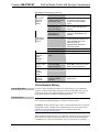
QuickMedia Wiring
The Crestron QuickMedia cable (sold under the name “CresCAT-QM”) contains one
CAT5E cable and one Cresnet cable in Siamese jackets. Installation of any QM
device is as simple as installing CresCAT-QM wires from the output of one device to
the input of another. Installations are flexible, affordable and fast. For more
information, refer to the latest revision of the Crestron MediaManager Applications
Guide (Doc. 6244), which is available for download from the Crestron website
(www.crestron.com/manuals
).
CresCAT-QM Cable
CresCAT-QM
Cable
NOTE: Do not untwist the two wires in a single pair for more than 1/3-1/2”
(0.84-1.27 cm) when making a connection. The twists are critical to canceling out
interference between the wires.
Operations & Installation Guide – DOC. 6307B FlipTop Media Center with Storage Compartment: QM-FTMCSC • 15

FlipTop Media Center with Storage Compartment Crestron QM-FTMCSC
The aggregate cable length of a signal path originating at a QM-FTMCSC and
terminating at a QM receiver must not exceed 450 feet (137 meters). Video signals
may experience a loss of quality over very long lengths of cable. This phenomenon is
due to the added resistance and capacitance of longer cable lengths and is not
peculiar to either Crestron and/or QuickMedia systems. To ensure sufficient
bandwidth, the maximum aggregate cable length should not exceed 450 feet. The use
of lower-resolution signals may allow increased cable length but must be tested by
the installer with the sources to be used. The QM pin assignment is based on the
EIA/TIA 568B RJ-45 Jack standard.
NOTE: When using CresCAT-QM wiring, four additional wires are included for
making Cresnet connections.
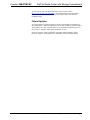
When connecting multiple QM devices, the route between a QM origination point
(transmitter) and a QM endpoint (receiver) cannot have more than two midpoints
(e.g. QM-MD7x2 or other QM switchers). Refer to the following diagram when
configuring a QM network.
NOTE: The aggregate length from transmitter to receiver cannot have a delay skew
or more than 22 ns.
NOTE: When used with a QM-RMCRX, delay skew should not exceed 15 ns.
QM Network Topology
QM-RMCRX-BA
QM-TX
QM
QM
QM
QM
QM
Origination Points Endpoints
QM
Midpoints
QM-FTMCSC
QM-MD7x2QM-MD7x2
QM-WMC
QM-RX
Identity Code
The Net ID of the QM-FTMCSC has been factory set to 0A. The Net IDs of multiple
QM-FTMCSC devices in the same system must be unique. Net IDs are changed
from a personal computer (PC) via the Crestron Toolbox (refer to “Establishing
Communication” on page 30).
When setting the Net ID, consider the following:
• The Net ID of each unit must match an ID code specified in the SIMPL™
Windows
®
program.
• Each network device must have a unique Net ID.
For more details, refer to the Crestron Toolbox help file.
16 • FlipTop Data Center with Storage Compartment: QM-FTMCSC Operations & Installation Guide – DOC. 6307B
Page is loading ...
Page is loading ...
Page is loading ...
Page is loading ...
Page is loading ...
Page is loading ...
Page is loading ...
Page is loading ...
Page is loading ...
Page is loading ...
Page is loading ...
Page is loading ...
Page is loading ...
Page is loading ...
Page is loading ...
Page is loading ...
Page is loading ...
Page is loading ...
Page is loading ...
Page is loading ...
Page is loading ...
Page is loading ...
Page is loading ...
Page is loading ...
Page is loading ...
Page is loading ...
Page is loading ...
Page is loading ...
-
 1
1
-
 2
2
-
 3
3
-
 4
4
-
 5
5
-
 6
6
-
 7
7
-
 8
8
-
 9
9
-
 10
10
-
 11
11
-
 12
12
-
 13
13
-
 14
14
-
 15
15
-
 16
16
-
 17
17
-
 18
18
-
 19
19
-
 20
20
-
 21
21
-
 22
22
-
 23
23
-
 24
24
-
 25
25
-
 26
26
-
 27
27
-
 28
28
-
 29
29
-
 30
30
-
 31
31
-
 32
32
-
 33
33
-
 34
34
-
 35
35
-
 36
36
-
 37
37
-
 38
38
-
 39
39
-
 40
40
-
 41
41
-
 42
42
-
 43
43
-
 44
44
-
 45
45
-
 46
46
-
 47
47
-
 48
48


Crestron QM-FTMCSC-NB Installation guide
- Category
- Numeric keypads
- Type
- Installation guide
- This manual is also suitable for
Ask a question and I''ll find the answer in the document
Finding information in a document is now easier with AI
Related papers
-
Crestron QMI-FTMC Installation guide
-
-
-
-
-
-
-
-
-
Other documents
-
 Cables Direct UT-899002 Datasheet
-
Unbranded 10103 Installation guide
-
 DOC-BOX 10102 Installation guide
-
ATEN 2X-031G Quick start guide
-
 Calculated Industries 6260 User manual
-
 John Deere Products & Services AC-6000SB User manual
-
luminii RGBW-SR Installation guide
-
 Crestron electronic MPS-250 User manual
-
 Crestron electronic TPS-GA-TPI User manual
-
 Crestron electronic TPS-15L User manual


