Page is loading ...

Crestron QM-MDM3X1
3 x 1 QuickMedia™ Mini-Switcher
Operations & Installation Guide

This document was prepared and written by the Technical Documentation department at:
Crestron Electronics, Inc.
15 Volvo Drive
Rockleigh, NJ 07647
1-888-CRESTRON
All brand names, product names and trademarks are the property of their respective owners.
©2007 Crestron Electronics, Inc.

Crestron QM-MDM3X1 3 x 1 QuickMedia™ Mini-Switcher
Contents
3 x 1 QuickMedia™ Mini-Switcher: QM-MDM3X1 1
Introduction ...............................................................................................................................1
Features and Functions................................................................................................ 2
Applications.................................................................................................................2
Specifications ..............................................................................................................3
Physical Description....................................................................................................5
Industry Compliance ................................................................................................... 7
Setup .......................................................................................................................................... 8
Network Wiring........................................................................................................... 8
QuickMedia Wiring..................................................................................................... 8
Identity Code ............................................................................................................... 9
Installation................................................................................................................. 10
Hardware Hookup .....................................................................................................13
Programming Software............................................................................................................14
Earliest Version Software Requirements for the PC ................................................. 14
Programming with Crestron SystemBuilder.............................................................. 14
Programming with SIMPL Windows ........................................................................ 14
Example Program...................................................................................................... 16
Uploading and Upgrading........................................................................................................ 17
Establishing Communication.....................................................................................17
Programs and Firmware ............................................................................................17
Program Checks ........................................................................................................ 18
Problem Solving ......................................................................................................................19
Troubleshooting......................................................................................................... 19
Check Network Wiring..............................................................................................19
Reference Documents................................................................................................ 20
Further Inquiries ........................................................................................................20
Future Updates ..........................................................................................................21
Return and Warranty Policies .................................................................................................. 22
Merchandise Returns / Repair Service ...................................................................... 22
CRESTRON Limited Warranty.................................................................................22
Operations & Installation Guide – DOC. 6608A Contents • i


Crestron QM-MDM3X1 3 x 1 QuickMedia™ Mini-Switcher
3 x 1 QuickMedia™
Mini-Switcher: QM-MDM3X1
Introduction
The QM-MDM3X1 is a compact 3 x 1 QuickMedia™ switcher designed to expand
the input capacity of a single QM-RMCRX-BA receiver or any device with a
QuickMedia (QM) input port. It attaches directly to the top of a QM-RMCRX-BA,
providing inputs for up to three QuickMedia Wall Plates, FlipTop Boxes and other
QM transmitters. It can also be installed beneath a table or in a closet to provide
localized switching of any three QM sources.
The QM-MDM3X1 behaves as a midpoint QM device just like any other QM
switcher. All signal routing is provided over inexpensive CAT5e type cable via
Crestron’s exclusive QuickMedia transport, supporting the distribution of high
resolution RGB, video, stereo audio and microphone signals up to a total of 450 feet
(137 meters) end to end. Up to two QM-MDM3X1s or other QuickMedia switchers,
distribution centers and distribution amplifiers may be cascaded in a given
QuickMedia signal path to support larger system configurations.
Regardless of the configuration, complete system operation can be made transparent
to the end user with all signal routing occurring smoothly under the command of the
MediaManager control system. Audio breakaway capability allows audio signals to
be selected independent of video signals.
Four built-in Cresnet
®
ports provide for distribution of Cresnet control signals and
power. The QM-MDM3X1 can furnish up to 41 Watts of Cresnet power when
powered by a dedicated PW-2420RU power supply (sold separately) or 16 Watts if
powered by a PW-2410RU (sold separately). The QM-MDM3X1 may also be
powered from any 2-Series control system or Cresnet power supply via the Cresnet
network.
NOTE: For QuickMedia wiring use CresCAT-QM, CresCAT-IM or quality
CAT5e/CAT6 cable with a maximum delay skew of 15 ns per 100 m. The maximum
aggregate cable length and delay skew between any QM transmitter (origination
point) and QM receiver (endpoint) is 450 feet (137 meters) and 22 ns. A maximum
of two QM midpoint devices may be inserted into a given QM signal path.
Exceptions apply; refer to each respective product manual for details.
Operations & Installation Guide – DOC. 6608A 3 x 1 QuickMedia™ Mini-Switcher: QM-MDM3X1 • 1

3 x 1 QuickMedia™ Mini-Switcher Crestron QM-MDM3X1
Features and Functions
• Compact 3 x1 QuickMedia™ switcher
• Provides easy input expansion for any QM receiver
• Mounts directly to pole mounted QM-RMCRX-BA
• Low profile design allows installation in furniture or closet
• Built-in Cresnet
®
power distribution
• Audio breakaway capability
Applications Applications
The following diagrams show a QM-MDM3X1 in a lecture hall and a business
application.
The following diagrams show a QM-MDM3X1 in a lecture hall and a business
application.
QM-MDM3X1 in a Lecture Hall Application QM-MDM3X1 in a Lecture Hall Application
2 • 3 x 1 QuickMedia™ Mini-Switcher: QM-MDM3X1 Operations & Installation Guide – DOC. 6608A

Crestron QM-MDM3X1 3 x 1 QuickMedia™ Mini-Switcher
QM-MDM3X1 in a Business Application
Specifications
Specifications for the QM-MDM3X1 are listed in the following table.
QM-MDM3X1 Specifications
SPECIFICATION DETAILS
Video/RGB
Switcher
3 x 1 selector switch; routes any of (3) QM
video input signals to (1) QM output
Gain 0 dB
Audio
Switcher
3 x 1 selector switch; routes any of (3) QM
audio input signals to (1) QM output
Gain 0 dB
Power
Power Consumption 9 Watts (0.375 Amps) @ 24 Volts DC
Recommended Power Supply
PW-2410RU or PW-2420RU (sold
separately)
(Continued on following page)
Operations & Installation Guide – DOC. 6608A 3 x 1 QuickMedia™ Mini-Switcher: QM-MDM3X1 • 3

3 x 1 QuickMedia™ Mini-Switcher Crestron QM-MDM3X1
QM-MDM3X1 Specifications (Continued)
SPECIFICATION DETAILS
Power (Continued)
Available Cresnet Power
16 Watts using PW-2410RU or
41 Watts using PW-2420RU
Cresnet Power Usage
9 Watts (0.375 Amps) @ 24 Volts DC with
no power supply connected to the 24 VDC
connector
Default Net ID 32
Minimum 2-Series Control
System Update File
1, 2
Version 3.137 or later
Environmental
Temperature 32º to 104ºF (0º to 40ºC)
Humidity 10% to 90% RH (non-condensing)
Heat Dissipation 50 BTU/Hr
Enclosure
Chassis
Steel, black matte powder coat finish,
convection cooled, vented top and sides
with allowance for proper ventilation of
attached QM-RMCRX-BA
Mounting
Freestanding, surface mount or attachment
to top of QM-RMCRX-BA (adhesive feet,
(4) “L” brackets and (4) strap brackets
included)
Dimensions
Height 1.17 in (2.96 cm)
Width 7.69 in (19.52 cm)
Depth 5.24 in (13.30 cm)
Weight 1.74 lbs (0.79 kg)
1. The latest software versions can be obtained from the Crestron website. Refer to the NOTE following
these footnotes.
2. Crestron 2-Series control systems include the AV2 and PRO2. Consult the latest Crestron Product
Catalog for a complete list of 2-Series control systems.
NOTE: Crestron software and any files on the website are for authorized Crestron
dealers and Crestron Authorized Independent Programmers (CAIP) only. New users
may be required to register to obtain access to certain areas of the site (including the
FTP site).
4 • 3 x 1 QuickMedia™ Mini-Switcher: QM-MDM3X1 Operations & Installation Guide – DOC. 6608A

Crestron QM-MDM3X1 3 x 1 QuickMedia™ Mini-Switcher
Physical Description
This section provides information on the connections, controls and indicators
available on your QM-MDM3X1.
QM-MDM3X1 Physical View (Front)
QM-MDM3X1 Physical View (Rear)
QM-MDM3X1 Overall Dimensions (Front View)
1.17 in
(2.96 cm)
QM-MDM3X1 Overall Dimensions (Top View)
5.24 in
(13.30 cm)
7.69 in
(19.52 cm)
Operations & Installation Guide – DOC. 6608A 3 x 1 QuickMedia™ Mini-Switcher: QM-MDM3X1 • 5

3 x 1 QuickMedia™ Mini-Switcher Crestron QM-MDM3X1
QM-MDM3X1 (Rear View)
1 2
3
4
5
7
8
6
Connectors, Controls & Indicators
#
CONNECTORS
1
,
CONTROLS &
INDICATORS
DESCRIPTION
1
QM IN (1 – 3)
(3) 8-wire RJ-45 female QuickMedia input
ports;
Connect to QM output ports of up to (3) QM
transmitters or other QuickMedia devices via
CresCAT-QM cable.
2, 3
2
QM OUT
(1) 8-wire RJ-45 female QuickMedia output
port;
Connects to QM input port of QM-RMCRX-
BA or other QuickMedia device via
CresCAT-QM cable.
2
3
SETUP
(button and LED)
(1) Miniature pushbutton and red LED, used
for touch-settable ID (TSID)
Used for setting network ID during initial
configuration or when the device is being
added/replaced.
4
G
(1) 6-32 screw, chassis ground lug.
5
NET
4
Four-position terminal block connector for
data and power. Connects to Cresnet control
network;
Normally provides Cresnet distribution
between QM-RMCRX-BA master port and
(3) QM transmitters.
Pin 1 (24) Power (24 Volts DC)
Pin 2 (Y) Data
Pin 3 (Z) Data
Pin 4 (G) Ground
6 PWR LED
(1) Green LED, indicates 24 Volts DC power
supplied from external power supply or
Cresnet control network.
7 NET LED
(1) Yellow LED, indicates communication
with Cresnet system.
8
24 VDC
4
(1) 2.1 mm barrel DC power jack,
24 Volt DC power input;
(power supply sold separately);
Passes through to NET ports to power
additional Cresnet devices.
6 • 3 x 1 QuickMedia™ Mini-Switcher: QM-MDM3X1 Operations & Installation Guide – DOC. 6608A

Crestron QM-MDM3X1 3 x 1 QuickMedia™ Mini-Switcher
1. Interface connectors for NET ports are provided with the unit.
2. For QuickMedia wiring use CresCAT-QM, CresCAT-IM or quality CAT5e/CAT6 cable with a
maximum delay skew of 15 ns per 100 m. The maximum aggregate cable length and delay skew
between any QM transmitter (origination point) and QM receiver (endpoint) is 450 feet (137 meters)
and 22 ns. A maximum of two QM midpoint devices may be inserted into a given QM signal path.
Exceptions apply; refer to each respective product manual for details.
3. The eight-pin RJ-45 QuickMedia transport port accepts CAT5E/CAT6 carrying audio, video and
microphone signals. The QM input port conforms to the 568B wiring standard. Refer to the following
table for connector pinouts.
RJ-45 PIN
NUMBER
WIRE COLORS
(EIA 568B)
QM ASSIGNMENT: RGB
QM ASSIGNMENT:
COMPOSITE, S-VIDEO,
COMPONENT AND AUDIO
1 WHITE/ORANGE
- RGB RED
- CHROMINANCE (- P
r
)
2 ORANGE
+ RGB RED
+ CHROMINANCE (+ P
r
)
3 WHITE/GREEN
- RGB GREEN
- LUMINANCE (- Y)
4 BLUE
+ DIGITAL AUDIO
+ DIGITAL AUDIO
5 WHITE/BLUE
- DIGITAL AUDIO
- DIGITAL AUDIO
6 GREEN
+ RGB GREEN
+ LUMINANCE (+ Y)
7 WHITE/BROWN
- RGB BLUE
- COMPOSITE (- P
b
)
8 BROWN
+ RGB BLUE
+ COMPOSITE (+ P
b
)
4. The QM-MDM3X1 can be powered via the 24 VDC jack or the NET port. Crestron recommends
using one or the other but not both. Be sure to use a Crestron approved power supply as another may
cause damage.
Industry Compliance
As of the date of manufacture, the QM-MDM3X1 has been tested and found to
comply with specifications for CE marking and standards per EMC and
Radiocommunications Compliance Labelling.
NOTE: This device complies with part 15 of the FCC rules. Operation is subject to
the following two conditions: (1) this device may not cause harmful interference and
(2) this device must accept any interference received, including interference that may
cause undesired operation.
This equipment has been tested and found to comply with the limits for a Class B
digital device, pursuant to part 15 of the FCC Rules. These limits are designed to
provide reasonable protection against harmful interference in a residential
installation. This equipment generates, uses and can radiate radio frequency energy
and if not installed and used in accordance with the instructions, may cause harmful
interference to radio communications. However, there is no guarantee that
interference will not occur in a particular installation. If this equipment does cause
harmful interference to radio or television reception, which can be determined by
turning the equipment off and on, the user is encouraged to try to correct the
interference by one or more of the following measures:
Reorient or relocate the receiving antenna.
Increase the separation between the equipment and receiver.
Connect the equipment into an outlet on a circuit different from that to
which the receiver is connected.
Consult the dealer or an experienced radio/TV technician for help.
Operations & Installation Guide – DOC. 6608A 3 x 1 QuickMedia™ Mini-Switcher: QM-MDM3X1 • 7

3 x 1 QuickMedia™ Mini-Switcher Crestron QM-MDM3X1
Setup
Network Wiring
When wiring the network, consider the following:
• Use Crestron Certified Wire.
• Use Crestron power supplies for Crestron equipment.
• Provide sufficient power to the system.
CAUTION: Insufficient power can lead to unpredictable results or damage
to the equipment. Please use the Crestron Power Calculator to help calculate
how much power is needed for the system (www.crestron.com/calculators
).
• For larger networks, use a Cresnet Hub/Repeater (CNXHUB) to maintain
signal quality.
For more details, refer to “Check Network Wiring” on page 19.
QuickMedia Wiring
The Crestron QuickMedia cable (sold under the name “CresCAT-QM”) contains one
CAT5E cable and one Cresnet cable in Siamese jackets. Installation of any QM
device is as simple as installing CresCAT-QM wires from the output of one device to
the input of another. Installations are flexible, affordable and fast. For more
information, refer to the latest revision of the Crestron MediaManager Applications
Guide (Doc. 6244), which is available for download from the Crestron website
(www.crestron.com/manuals
).
CresCAT-QM Cable
CresCAT-QM
Cable
NOTE: Do not untwist the two wires in a single pair for more than 1/3-1/2”
(0.84-1.27 cm) when making a connection. The twists are critical to canceling out
interference between the wires.
8 • 3 x 1 QuickMedia™ Mini-Switcher: QM-MDM3X1 Operations & Installation Guide – DOC. 6608A

Crestron QM-MDM3X1 3 x 1 QuickMedia™ Mini-Switcher
The aggregate cable length of a signal path originating at a QM transmitter and
terminating at a QM receiver (with a QM-MDM3X1 in between) must not exceed
450 feet (137 meters). Video signals may experience a loss of quality over very long
lengths of cable. This phenomenon is due to the added resistance and capacitance of
longer cable lengths and is not peculiar to either Crestron and/or QuickMedia
systems. To ensure sufficient bandwidth, the maximum aggregate cable length
should not exceed 450 feet. The use of lower-resolution signals may allow increased
cable length but must be tested by the installer with the sources to be used. The QM
pin assignment is based on the EIA/TIA 568B RJ-45 Jack standard. Check your
specific device, some (those without delay skew compensation) can use only 300 feet
(90 meters) or less based upon resolution.
NOTE: When transmitting S-video, luminance uses the green video pathway and
chrominance uses the red video pathway. When transmitting composite video, the
signal is carried on the blue video pathway.
NOTE: When using CresCAT-QM wiring, four additional wires are included for
making Cresnet connections.
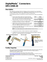
When connecting multiple QM devices, the route between a QM origination point
(transmitter) and a QM endpoint (receiver) cannot have more than two midpoints
(e.g. QM-MDM3X1 or other QM switchers). Refer to the following diagram when
configuring a QM network.
NOTE: The aggregate length from transmitter to receiver cannot have a delay skew
of more than 22 ns.
QM Network Topology
TPS-12G/15G-QM-L
QM-TX
QM
QM
QM
QM
Origination Points Endpoint
QM
Midpoints
QM-FTDC
QM-MDM3x1QM-MD7x2
QM-WMC
Identity Code
The Net ID of the QM-MDM3X1 has been factory set to 32. The Net IDs of multiple
QM-MDM3X1 devices in the same system must be unique. Net IDs are changed
from a personal computer (PC) via the Crestron Toolbox (refer to “Establishing
Communication” on page 17).
When setting the Net ID, consider the following:
• The Net ID of each unit must match an ID code specified in the SIMPL™
Windows
®
program.
• Each network device must have a unique Net ID.
For more details, refer to the Crestron Toolbox help file.
Operations & Installation Guide – DOC. 6608A 3 x 1 QuickMedia™ Mini-Switcher: QM-MDM3X1 • 9

3 x 1 QuickMedia™ Mini-Switcher Crestron QM-MDM3X1
Installation
The QM-MDM3X1 is designed to mount directly on top of a QM-RMCRX-BA (sold
separately) or to the underside of a horizontal surface such as a desktop. It can also
be used freestanding.
Tools required:
• Phillips screwdriver
• Drill/driver (for underside mounting only)
Supplied Hardware for the QM-MDM3X1
DESCRIPTION PART NUMBER QUANTITY
Mounting bracket
(for attachment to QM-RMCRX-BA)
2018547 4
Mounting bracket
(for underside mounting)
2009632 4
Adhesive feet 2002389 4
Attaching to QM-RMCRX-BA
To attach the QM-MDM3X1 to the top of a QM-RMCRX-BA, use the following
procedure:
1. Attach the four adhesive “feet” provided with the QM-MDM3X1 to the
bottom surface, one in each corner.
2. Remove the front and rear screws from both side panels of the
QM-MDM3X1 and the front and rear screws from both side panels of the
QM-RMCRX-BA, as shown in the diagram on the following page.
3. Place the QM-MDM3X1 on top of the QM-RMCRX-BA and install the two
mounting brackets on each side of the pair, using the side panel screws from
step 2.
10 • 3 x 1 QuickMedia™ Mini-Switcher: QM-MDM3X1 Operations & Installation Guide – DOC. 6608A

Crestron QM-MDM3X1 3 x 1 QuickMedia™ Mini-Switcher
Attaching QM-MDM3X1 to a QM-RMCRX-BA
Mounting Bracket (4)
(2018547)
Underside Mounting
To attach the QM-MDM3X1 to the underside of a horizontal surface, use the
following procedure:
QM-MDM3X1 Bracket Dimensions for Underside Mounting
4.47 in
(11.33 cm)
8.54 in
(21.69 cm)
1. Remove the front and rear screws from both side panels of the
QM-MDM3X1, as shown in the diagram on the following page.
2. Install the two L-shaped mounting brackets on each side of the
QM-MDM3X1, using the side panel screws from step 1.
Operations & Installation Guide – DOC. 6608A 3 x 1 QuickMedia™ Mini-Switcher: QM-MDM3X1 • 11

3 x 1 QuickMedia™ Mini-Switcher Crestron QM-MDM3X1
3. Use four #6 hardware screws (not supplied) to secure the unit to the
underside of the surface.
Underside Mounting the QM-MDM3X1
Mounting Bracket (4)
(2009632)
NOTE: Do not over-tighten the screws as this may damage the surface and/or the
unit.
NOTE: To prevent overheating, do not operate this product in an area that exceeds
the environmental temperature range listed in the specifications table. Consideration
must be given if installed in a closed or multi-unit rack assembly, inside a closed
desk or in a closed podium since the operating ambient temperature of these
environments may be greater than the room ambient temperature. Contact with
thermal insulating materials should be avoided on all sides of the unit.
NOTE: When mounting the QM-MDM3X1 to the underside of a surface, to ensure
proper ventilation, make sure to orient the unit so the ventilation holes on the top
face upward. Similarly, when mounting to a vertical surface, orient the unit so the
ventilation holes on one of the sides face upward.
12 • 3 x 1 QuickMedia™ Mini-Switcher: QM-MDM3X1 Operations & Installation Guide – DOC. 6608A

Crestron QM-MDM3X1 3 x 1 QuickMedia™ Mini-Switcher
Hardware Hookup
Connect the Device
Make the necessary connections as called out in the illustration that follows this
paragraph. Refer to “Network Wiring” on page 8 before attaching the 4-position
terminal block connector. Apply power after all connections have been made.
Hardware Connections for the QM-MDM3X1
CRESNET:
CONNECT TO CRESNET
CONTROL NETWORK
24V DC:
FROM 24 VOLT DC
POWER SUPPLY
QM IN:
QUICKMEDIA PORTS CARRY
AUDIO, VIDEO, RGB AND
MICROPHONE SIGNALS
QM OUT:
QUICKMEDIA PORT CARRIES
AUDIO, VIDEO, RGB AND
MICROPHONE SIGNALS
GROUND
NOTE: For optimum performance, Crestron strongly recommends using
CresCAT-QM cable, available from Crestron. Other high-quality/low skew
CAT5e/CAT6 wiring may also be used with varying performance.
NOTE: Ensure the unit is properly grounded.
NOTE: The maximum continuous current from equipment under any external load
conditions shall not exceed a current limit that is suitable for the minimum wire
gauge used in interconnecting cables. The ratings on the connecting unit’s supply
input should be considered to prevent overloading the wiring.
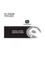
Ground Wire Connections
Proper grounding is required. Connect the ground from the QM-MDM3X1 to earth
ground. Connect the Cresnet shield at the QM-RMCRX-BA to the chassis ground
provided on the QM-RMCRX-BA. The QM-RMCRX-BA chassis must also be
connected to an earth ground (building steel). Refer to the following grounding
diagram.
Ground Wire Connections
QM-RMCRX-BA
QM-MDM3X1
24
Y
Z
G
Shield
Ground
Wire to
Earth
Ground
Ground
Terminal
to Earth
Ground
Cresnet
Ground Wire
NOTE: Do not connect the shield to earth ground at the QM-MDM3X1.
Operations & Installation Guide – DOC. 6608A 3 x 1 QuickMedia™ Mini-Switcher: QM-MDM3X1 • 13

3 x 1 QuickMedia™ Mini-Switcher Crestron QM-MDM3X1
Programming Software
Have a question or comment about Crestron software?
Answers to frequently asked questions (FAQs) can be viewed in the Online Help
section of the Crestron website. To post a question or view questions you have
submitted to Crestron’s True Blue Support, log in at http://support.crestron.com.
First-time users will need to establish a user account.
Earliest Version Software Requirements for the PC
NOTE: Crestron recommends that you use the latest software to take advantage of
the most recently released features. The latest software is available from the Crestron
website.
Crestron has developed an assortment of Windows
-based software tools to develop
a Cresnet system. For the minimum recommended software versions, visit the
version tracker page of the Crestron website (www.crestron.com/versiontracker
).
Programming with Crestron SystemBuilder
Crestron SystemBuilder is the easiest method of programming but does not offer as
much flexibility as SIMPL Windows. For additional details, download
SystemBuilder from the Crestron website and examine the extensive help file.
Programming with SIMPL Windows
NOTE: While SIMPL Windows can be used to program the QM-MDM3X1, it is
recommended to use SystemBuilder for configuring a QuickMedia system.
SIMPL Windows is Crestron’s premier software for programming Crestron control
systems. It is organized into two separate but equally important “Managers”.
Configuration Manager
Configuration Manager is the view where programmers “build” a Crestron control
system by selecting hardware from the Device Library.
• To incorporate the QM-MDM3X1 into the system, drag the QM-MDM3X1
from the Cresnet Control Modules | QM Series folder of the Device Library
and drop it in the System Views.
14 • 3 x 1 QuickMedia™ Mini-Switcher: QM-MDM3X1 Operations & Installation Guide – DOC. 6608A

Crestron QM-MDM3X1 3 x 1 QuickMedia™ Mini-Switcher
Locating the QM-MDM3X1 in the Device Library
• The system tree of the control system displays the device in the appropriate
slot with a default Net ID as shown in the following illustration.
C2Net Device, Slot 9
• Additional QM-MDM3X1 devices are assigned different Net ID numbers as
they are added.
• If necessary, double click a device to open the “Device Settings” window
and change the Net ID, as shown in the following figure.
“QM-MDM3X1 Device Settings” Window
Operations & Installation Guide – DOC. 6608A 3 x 1 QuickMedia™ Mini-Switcher: QM-MDM3X1 • 15

3 x 1 QuickMedia™ Mini-Switcher Crestron QM-MDM3X1
• The ID code specified in the SIMPL Windows program must match the Net
ID of each unit. Refer to “Identity Code” on page 9.
Program Manager
Program Manager is the view where programmers “program” a Crestron control
system by assigning signals to symbols.
The symbol can be viewed by double clicking on the icon or dragging it into Detail
View. Each signal in the symbol is described in the SIMPL Windows help file (F1).
Example Program
An example program for the QM-MDM3X1 is available from the Crestron website
(www.crestron.com/exampleprograms).
16 • 3 x 1 QuickMedia™ Mini-Switcher: QM-MDM3X1 Operations & Installation Guide – DOC. 6608A
/