Page is loading ...

Since its introduction to the modeling scene in 1973, the Kadet series has set the
industry standard for R/C trainers. More people have learned to fly with a Kadet
than any other trainer in history. Its popularity led directly to the development of
the Kadet Junior, the Kadet Senior, and the Kadet Seniorita. The Kadet Mark II is
a refined development of the famed Kadet Mark I trainer and is intended specially
for 4-channel flight training. If you have the assistance of a skilled R/C flier during
the initial test and training flights, then full 4-channel control with ailerons can be
used from the beginning, although some R/C instructors feel it is best to get in some flying on rudder first before advancing
to ailerons. If no expert assistance, is available for first flights, our recommendation is that you begin with 3 channels only,
with rudder as the main turning control instead of ailerons. Then, after you gain confidence, go to 4
-channel control with
ailerons.
Be sure to read the "Basics of Radio Control" booklet included with this kit. It will provide you with the basic knowledge that
you will need to be successful in the challenging hobby of radio controlled model aircraft. From the selection of radio
equipment to that first exciting flight, the "Basics of Radio Control" will be invaluable to beginners and more experienced
pilots as well.
Radio Equipment Requirements
Selection of radio equipment should be based on the amount of money you wish to spend, the type of airplanes you intend
to fly, and your future goals in the hobby. Although the Kadet can be flown on two, three, or four channels, a good four-
channel radio will last for years and can be used in more advanced models when your flying skills improve. Be certain that
the frequency transmitted by your radio is approved for use in R/C model aircraft. Using a frequency assigned to surface
vehicles (cars, boats) not only endangers your model to interference from model car or boat drivers (who may not even be
in sight), it is also against the law.

.
Engine Size
We are of the opinion that R/C trainers should
have adequate power for such things as grass
field takeoffs, beating their way upwind, etc. For
cruising around and learning to fly, throttle back
with the knowledge that power is available when
needed. Therefore, we generally think that a .29
to .40 size engine is best for the Mark II. If a .25
is used, the model should be kept light, without
a lot of heavy finish. A .25 would also serve
adequately on two or three channels.
Remember that a muffler will reduce engine
power and allowance should be made for this. If
you live at high altitude, engines will not develop
power equivalent to that delivered at sea level.
A Note on Mufflers
Unless you are one of the lucky few who has a flying site miles away
from any sort of civilization, you should use an effective muffler on
your engine. The sound of an unmuffled R/C engine can be
annoying to anyone within earshot. The last thing you want to do is
turn potentially friendly neighbors into enemies that could, in the
worst case, go so far as to have all flying activity at your field shut
down.
Most manufacturers supply good mufflers with their engines. If for
some reason you have an engine without a muffler, or the supplied
muffler doesn't fit the Kadet, you can use one of the many
aftermarket mufflers. Tatone's Extended Peace Pipe muffler, Mac's
Scotsman or Expansion mufflers, DuBro's Muff-I-Aire and Mini-Muff-
I-Aire, as well as others will all fit the Kadet.
Recommended Glues
There are so many different glues available today for model construction that it can be confusing for the newcomer. To
simplify matters, most glues can be classified as one of these basic types:
1. Fast-drying cyanoacrylate adhesives (CA) or "super glues" such as SIG CA, Hot Stuff, Jet, etc .....
2. Easy-to-use water-base wood glues such as SIG-BOND (yellow) and SIG SUPER-WELD (white).
3. Super strong two-part epoxy glues such as SIG KWIK-SET (5-minute cure) and SIG EPOXY (3-hour cure).
4. Traditional solvent-base model cements such as SIG-MENT.
Each of these types has different characteristics and advantages. Often times, the choice of which type to use is strictly a
matter of personal preference based on your prior experience with a previous model. Some of the steps in the book call
out the type of glue to use for that particular assembly. In other areas you can use your own judgement as to which type is
best suited to the purpose and to your building schedule. For general construction of the Kadet Mark II, we recommend the
use of cyanoacrylate adhesives or SIG-BOND. Even if you plan to use CA, SIGBOND will come in handy for gluing parts
such as wing leading edge sheeting or center sheeting where you need to apply glue to several parts in one operation.
You should also have on hand some epoxy glue, both 5-minute and slow dry, for areas subject to high stress or joints
involving metal parts.
Cyanoacrylate adhesives have become very popular with modelers because of their fast drying times. With CA, you can
virtually build a structure from start to finish without having to wait for the glue to dry. Most brands, including SIG CA, come
in three different viscosities: thin, medium, and thick.
Thin CA has a watery consistency and uses capillary action to penetrate and soak. into a joint. Since it is so thin
and dries so quickly, the parts to be joined must be in firm contact with each other before application of the glue.
Use thin CA for the initial assembly of balsa parts over the plans.
Medium viscosity CA (SIG CA PLUS) can also be used for initial assembly in the same manner as the thin, but it
takes a little longer to dry. Joints made initially with thin CA should be reglued with medium CA for additional
strength. Medium CA should also be used when gluing plywood, spruce, or hardwoods.
Thick CA is good for gluing doublers to fuselages and forming fillets in high stress areas.
The drying time for all CA's can be speeded up by spraying an accelerator (such as SIG KWIK
-
SHOT) right on the joint.
CAUTION:
Some people have experienced allergic reactions when exposed to epoxy or cyanoacrylate
glues. This is very rare. However, it is always important that such glues, and also paints,
thinners, and solvents, be used with adequate ventilation to carry fumes away.

.
You Can't Get Along Without A Good Sanding Block
An assortment of different size sanding blocks are indispensable tools for
model construction. A good general purpose block can be made by
wrapping a 9" x 11" sheet of sandpaper around a piece of hardwood or
plywood. Use three screws along one edge to hold the overlapped ends of
the sandpaper. Put 80-grit paper on the block during general construction.
Switch to 220 grit paper for final sanding just before covering.
In addition to the large block, there are places where a smaller one is
handy. (See photos 17 and 24.) Also, a sandpaper "file" can be made by
gluing sandpaper to a flat spruce stick for working in tight places.
Cutting Out Printed Parts
A jig saw is best for this job. Cut just outside the lines, leaving all of the black line
on the part. When fitting the part into place on the model, use the sanding block
to bring the edges to an exact fit. If a modeling knife is used to cut out the parts,
don't cut too close to the lines -
leave some extra wood outside the line and finish
the edge with the sanding block.
About The Building Sequence
The quickest and most efficient way to complete a model is to work on several pieces at the same time. While the glue is
drying on one section, you can start on or proceed with another part. Work can even go forward on several sections of the
same assembly at the same time, such as the front and rear sections of the fuselage.
Keep in mind that the number sequence used in these instructions was chosen as the best way to explain the building of
each major component and is not intended to be followed in exact one-two-three fashion. Start on the wing at No.1 and
after doing as many steps as is convenient, flip over to "FUSELAGE CONSTRUCTION" and do a step or two there, then
over to "TAIL CONSTRUCTION" and so forth. You will, of course, arrive at points where you can go no farther until
another component is available. Plan ahead, read the instructions completely and study the full size plans before
beginning construction.
Notes Before Beginning Construction
Any references to right or left refers to your right or left as if you were seated in
the cockpit.
To build good flying models, you need a good straight building board. Crooked
models don't fly well! The building board can be a table, a workbench, a reject
"door core" from the lumber yard, or whatever - as long as it is perfectly flat and
untwisted. Cover the top surface of the building board with a piece of celotex-
type
wall board or foam board, into which pins can be easily pushed. Don't hesitate to
use plenty of pins during assembly to hold drying parts in correct position.
When pinning and gluing parts directly over the full-
size plans, cover the plan with
wax paper or plastic kitchen wrap to prevent gluing the parts to the plans.
Don't use a ball point pen for making marks on the model during construction. If
not sanded off, these ink marks will show through the model's final finish. Use a
pencil instead of a pen.
Pins can be pushed through all pieces in the kit without any lasting damage.
Don't be afraid to use plenty of pins when planking with SIG-BOND.

.
Leave all die-cut parts in the sheets until needed in construction. Then remove the pieces from the sheets carefully. If
difficulty is encountered, do not force the part from the sheet - use a modeling knife to cut it free.
The die-cut balsa wing ribs are identified within the wing construction section. The die-cut plywood parts can be identified
using the plans and the "Key To Plywood Parts". Mark the identification numbers on the corresponding parts before
removing them from the die-cut sheets.
All of the other parts can be identified by the "Complete Kit Parts List". Sort the different sizes of sticks and sheets into
individual piles to avoid confusion during building. Cut all long pieces of balsa first, followed by medium lengths, before
cutting up any full-length strips into short pieces. Pick out the two hardest 1/4" sq. balsa sticks to use as pushrods.
NOTE: Save any scrap balsa and plywood until the model is completely done. Some of it may be called for during
construction.
COMPLETE KIT PARTS LIST
Printed Balsa Sheets
1 3/32"x6"x36" SHEET #1; Left
Fuse Side, FF, DGF, FP, WT
1 3/32"x6"x36" SHEET #2;
Right Fuse Side, FF; F-1B,
DGF, WT
1 1/4"x3"x18" SHEET #3; R-1, R-2,
R-3, DG, FB
1 3/32"x3"x4-
1/2" SHEET #4, WF,
F-2
Die-Cut Balsa Sheets
4 3/32"x3"x18" SHEET #5; W2
Wing Ribs
1 3/32"x3"x18" SHEET #6;
W1 Wing Ribs
Sheet Balsa
2
1/16"x3"x36" Stabilizer Sheeting
(or 3 ea. 1/16"x3"x24")
3 3/32"x1-1/2"x30" Trailing
Edge Bottom Planking
8 3/32"x3"x30" Planking for Wing
Leading Edge, Center Section,
Wingtip, and Fuselage Top and
Bottom
1 1/8"x3"x24" Cabin Doublers,
First Piece Aft of Lite-Ply Floor
1 1/8"x3-9/16"x9" Spar Web
Material
1 1/4"x3"x3-5/16" LGB
Block Balsa
2 3/4"x2"x3" Wing Fairing Blocks 1 3/4"x4"x3-1/4" Windshield
Block WS
Stick Balsa
4 3/32"x3/16"x36" Capstrips 2
3/32"x1"x36" Trailing Edge
Top Planking
4 1/8"x3/8"x36" Stabilizer Frame 4 13/64"x13/64"x36" Rear Wing
Spar, Trailing Edge Spar,
Fuselage Stringers
8 1/4"x1/4"x36" Top Front Wing
Spars, Fuselage Structure,
Crosspieces
1 1/4"x1/2"x12" Fuselage
Structure (Top of cabin,
one fuselage side.)
3 1/4"x1/2"x36" Bottom Front Wing
Spars, Spar Doublers, Fuselage
Structure
1 3/4"xTriangle x6" Firewall
Braces
Special Shaped Balsa
2 3/16"x3/8"x1/4"x28" Leading
Edge
1 1/4"x2"x8" Tapered Sheet
for Rudder
1 1/4"x2"x24" Tapered Sheet for
Elevator
1 5/16"x1-1/8"x7" Center Section
Trailing Edge
2 5/16"x1-1/8"x24" Ailerons 2 3/8"x3/4"x3" FT (Sawn
Wedges)
Hardwood
2 1/4" dia.x5-1/4" Wing Hold-On
Dowels
1 3/8"x3/8"x4" Basswood
Cowl Mounting Block
Material
Die-Cut Plywood
1 3/32"x3"x7-
1/2" Dihedral Braces
WP and WPB
1 3/32"x4-1/2"x9-1/4"
Firewall Parts F-1A and F-
1C
1 1/8"x3-3/4"x11-1/4" FN Nose
Doublers
1 1/8"x12-1/2"x4-1/2" Cabin
Formers F-3 and F-4
Sawn Plywood
1 3/32"x2-1/2"x3-1/2"; LGP
Landing Gear Plate
1 1/8"x4"x12"; Cabin
Bottom
Miscellaneous
1 .090x1-1/2"x15-9/16" Formed
Aluminum Main Landing Gear
1 Formed Nose Gear Wire 1 Left-Hand Formed Aileron Horn
with Brass Bearing
1 Right-
Hand Formed Aileron Horn
with Brass Bearing
1 Injection Molded Plastic Cowling 1 2"x24" Glass Cloth Tape
for Wing Center Joint
1 Full-Size Printed Plan 1 36 Page Photo-Illustrated
Instruction Booklet
1 "Basics of Radio Control" Booklet 1 3"x4-1/2" Stik-Tite Decal

.
Hardware
4 4-40x3/8" Mounting Bolts for Nose
Gear Bearing
4 4-40x3/4" Mounting Bolts for
Main Landing Gear
4 6-32x3/4" Mounting Bolts
for Engine Mounts
2 8-32x1-1/2" Mounting Bolts
for Wheel Axles
4 No.2x1/2" Sheet Metal Screws for
Control Horns
4 No.4x1/2" Sheet Metal Screws
for Cowling
1 6-32x1/4" Self-Tapping Bolt
for Steering Arm
4 8-32 Hex Nuts for Axle Bolts
8 4-40 Blind Nuts for Nose Gear Bearing
and Landing Gear
4 6-32 Blind Nuts for Engine
Mounts
2 Molded Glass Filled Engine
Mounts
1 5-32" Molded Nylon Nose
Gear Bearing
1 5/32" Molded Nylon Nose Gear
Steering Arm with Brass Insert
1 Medium Molded Nylon Control
Horn for Rudder
1 Large Molded Nylon Control
Horn for Elevator
2 4-40 Molded Nylon Aileron
Connectors
4 2-56x10" Threaded RlC Rods
(2Iailerons, 1/rudder, 1/elevator)
4 2-56 R/C Links (may be metal
or nylon)
12 Easy Hinges 1 Push rod Connector
Assembly
WING CONSTRUCTION
1.
Cut 9 1/16" off the end of each of two pieces 1/4"x1/2"x36" main spar stock. Glue
these pieces to the remainder as center section spar doublers. Cut two pieces of
1/4" square stock 28 5/8" long. Cut two other pieces 9 1/16" long. Glue the 9 1/16"
pieces to the 28 5/8" pieces in the same way as shown in Picture 1 of the
1/4"x1/2" bottom front spar.
2.
These cross section drawings show the placement of the doublers.
3.
Place two of the 3/32"x3"x36" pieces of wing sheeting wood on the plan with one end on the wing center line. Trim off the
other end of the wood at the outer edge of the last wing rib. Save the scrap pieces.
4.
Place the two 3/32"x1-1/2"x36" pieces of wing sheeting wood on the plan with one end on the wing center line. Trim off the
other end of the wood at the outer edge of the last wing rib. Save the scrap pieces.
5.
a. Pin one of the 3" wide pieces to
the plan.
b. Pin one of the 1 Y2" wide pieces
to the plan
6.
a. Use some end scrap to make the
tip planked section. (Be sure you
first cut long pieces from the
scrap for the center section
before using the remaining scrap
for the tip.)
b. Glue the seams between these
pieces when pinning them down
to the plan.
c. Cut cap strips to fit between the
sheets.
About Wing Dihedral and Ailerons
We receive occasional comments that the Kadet appears to have too much
dihedral for the ailerons to work effectively. While individual builders have
reduced the dihedral on their own initiative (and the Kadet flies OK with less
dihedral), we do not believe this course is either advisable or necessary for
beginners. Reducing the dihedral will make the model roll easier but it also
decreases hands-
off stability and this is not a good situation for a novice RC flier.
During the first periods of learning to fly RC, beginners should not attempt to roll
their Kadet but should concentrate on practicing good turns. When the student
pilot can easily handle the Kadet in take-off, level flight, and landing, only then
should stunts be attempted.

.
7. Leave the center section bottom planking pieces until later, after the wing is
assembled.
8.
Stack all of the ribs and pin them together. Use scrap wood in the spar holes to
align the ribs accurately. Sand the ribs even. Even the front and back also. The rib
sanding process may reduce the height of the ribs slightly and thereby reduce the
height of the spar slots. Before unpinning the rib stack, check the spar slots with a
piece of spar wood. Deepen the slot, if necessary, so that the spar will go
completely into the ribs. Do not oversize the slots.
NOTE: The 3/16" sq. provided in the kit for the wing is intentionally slightly
oversize to allow for shaping the trailing edge to correct airfoil contour. The 3/16"
sq. can be confused with 1/4". Segregate the two sizes of sticks before cutting
pieces from them.
9.
Four W-l ribs are supplied on a die cut sheet. For the two W-IA ribs required, take two of the W-2 ribs and convert them to
W
-
IA ribs by use of the pattern shown above.
10.
a. Pin and glue the front spar assembly previously done in Step 1 to the front bottom planking. Cut the spar to be the
same length as the planking sheet.
b. Using several ribs as a locating guide so that the rear spar is correctly spaced to accept all of the ribs easily, pin and
glue the 3/16" sq. rear spar on the rear bottom planking. Cut the spar to be the same length as the planking sheet.
11.
Glue and pin the ribs in place. Glue them to the planking and cap strips as well as to the spars.
12.
Using the dihedral gauge as a guide, glue the center W-l rib to the spars and planking at a slight angle. Pin to hold it at this
angle until the glue dries.
Note About 3" Sheet Width
Balsa sheet width varies from 3" to 3 1/16". Therefore the 1/4"x1/2" bottom spar may be entirely on the
sheet or protruding off of it slightly, as shown in the step-by-step drawings that follow. This small variation
in width causes no problem in the assembly of the wing.

.
13.
Pin and glue the 3/16" sq. back edge of
the wing on to the back of the ribs and to
the planking.
NOTE: At the tip end leave 3/16" square
sticking out to be trimmed to fit the wing
tip later in step 18.
NOTE: These diagrams are for reference only and are intended to aid your
understanding of the wing construction.
Leading Edge
1 Glue the bottom
spar and the rear
spar at the same
time- to the bottom
planking sheets.
2 Glue the ribs in
place on the spars
and to the bottom
planking and the
cap strip.
3 Glue the shaped
leading edge to the
bottom planking.
4 Glue the 1/4"
square top spar
into the ribs.
5 Apply Sig-Bond to
the leading edge
ribs and top front
spar. Pin and glue
the planking to the
leading edge first.
Use pleanty of
pins.
6 Bend the planking
sheet down to the
ribs and the top front
spar. Use pins to
hold it down. If
necessary, wet the
top of the wood with
a sponge to make it
pliable. Don't use water unless required to get the wood in place.
7 Later, when the
wing is completed
and removed from
the building board,
shape the leading
edge to airfoil
contour.
14.
Pin and glue the 1/4"x3/8" special
shaped leading edge in place on the
front of the ribs and to the planking.
NOTE: At the tip end leave the leading
edge long enough to be trimmed later to
fit the wing tip WT in step 18.
15.
Cut out the WT wingtip pieces from the
printed balsa sheets #1 and #2. Finish
evenly to the outside line with a sanding
block.

.
16. Trim a bevel on the top and bottom
using the inside line of the gray shaded
portion as a guide for cutting.
Trailing Edge
1 The rear planking
and the spar setup
are done in the same
manner as step one
of the leading edge.
Then glue the ribs to
the spars, the bottom
planking and the
bottom cap strips.
2 Add the 3/16" square
back edge of the
wing, gluing it to the
planking and the
backs of the ribs.
3 Sand down the 3/16"
square back edge of
the wing to conform
to the top line of the
ribs.
4 Pin and glue the
3/32"x1" wide top
rear planking in
place on the ribs and
the 3/16" square
back.
5 Complete the wing
assembly by adding
the top capstrips on
all ribs which do not
have planking on
them.
17.
Finish the beveled edges with a small
sanding block.
18.
a. Use the Tip Guide pattern to set
the angle of WT. If WT does not
sit properly in place at this angle,
sand to fit snugly against the rib
and bottom planking.
b.
Trim the end of the 3/16" sq. back
edge of the wing to fit against
WT.
c. Glue WT to the wing
19.
Using the prepared top spar (Paragraph 1), cut the end at an angle to fit against WT. (The Tip Guide can be used for this
angle also.)

.
20.
a. Glue the spar into the rib
notches.
b. Glue the angled end against WT.
21.
Sand the ribs and the bevel on WT to a
good match. Use paper on the block to
keep from cutting down the ribs while
WT is being shaped.
22.
Sand the rest of the wing lightly with a large block. Do not oversand.
23.
A small sanding block is handy to touch up the ribs.
24.
The 3/16" sq. back piece should be beveled slightly on the top to follow the wing contour.
25.
Cut seven 1
-
1/4" wide strips from the 1/8" x 3
-
9/16" x 9" balsa included in the kit.
26.
Trim each piece of web to fit snugly
between the ribs.
27.
a. Use the odd piece for the narrow
spaced ribs in the center.
b. Glue the web pieces to the spars
and to the bottom planking.
c. Webbing ends here at the 4th rib
from the center.
28.
Trim the tops of the web pieces so that they are even with the top of the main spar.
29.
Sand the web pieces smooth.
30.
a. Glue the spar and web.
b.
Put glue on each rib between the spar and the leading edge and on the leading edge also.
31.
Pin the leading edge 3/32"x3"x36" top planking sheet in place starting at the leading edge. Use plenty of pins to hold it to
the ribs, the tip and the spar. If it will not easily bend in place from the leading edge to the spar, wet the top of the sheet with
a cotton swab to make it more pliable and curl it into place. Don't wet it unless it is necessary.

.
32.
Glue the 3/32"x1"x36" rear top planking sheet in place. Use the waste end for other planking.
33.
Add a piece of 3/32"x3"x36" planking sheet to the top of the wing tip.
34.
Complete the wing tip planking by fitting pieces of 3/32" planking into the remaining opening.
35.
a. Pin and glue the 3/32" x 3/16" cap strips onto the top of each rib.
b.
The three center section ribs are not cap stripped.
NOTE:
In preparing the Mark II for production, an improvement was made in wing center section
construction, so your model will not look exactly like the prototype Mark II on the label.
36.
Plank the center in the same way as the
tip with 3/32" sheet.
NOTE:
Some photos showing
methods of construction are of
other models, but the
procedure is the same for the
Kadet MK II.
37.
Remove the wing from the board and
trim off the planking scrap.
38.
Sand the tip planking flush with WT.
39.
Carve the leading edge to airfoil contour.

.
/tr>
40. Sand the leading edge smooth using a long sanding block. Take your time with this step and try to keep the shape uniform
along the entire leading edge.
41.
Round the edge of the tip so it will not be knife sharp.
42.
a. Sand the top of the cap strips and planking even.
b.
Do the same thing on the bottom.
Repeat steps 1 through 42 for the opposite wing half.
43.
Set the wing halves on a flat surface with one tip blocked up and the other half flat
on the table.
44.
Raise the one tip 4" at the last W-2 rib. If the joint in the center does not match
perfectly, sand one or both center ribs until it does. Glue the halves together with
epoxy glue. Have a "wet" joint to insure that the glue will fill any gaps in the seam.
It is particularly necessary that the planking sheets, the spars and the leading and
trailing edges are thoroughly glued to each other. Take up the wing as soon as
the glue has set. It is easier to remove the excess that has squeezed out of the
joint if it is peeled off before it cures completely.
45.
Check the servo and/or servo tray you intend to use for the ailerons, and saw out
an opening in the W-1 ribs to accommodate it. The plans show a 2-3/8" hole
between WP and WPB, which is large enough to fit most standard servos (see the
fuselage side view). If your aileron servo is exceptionally large, the opening may
need to be longer.
46.
Cut the slots in the other W
-
l ribs for WP.

.
47.
a. Epoxy glue WP to the spars, ribs & planking.
b. Add WPB. (May need sanding to fit, depending on location.)
c. Frame sides of servo compartment with scrap leading edge wood.
d. Hardwood blocks for servo mount screws.
48.
Cut, pin and glue pieces of 3/32" planking sheet to the bottom of the center
section of the wing, leaving the servo hole open. Sand center section bottom
smooth.
49.
A typical R/C servo installed in the Kadet wing.
NOTE: Skip this instruction if you are going to have ailerons and go to picture 50. If you are not going to have ailerons, refer
to this picture and drawing then skip pictures 50, 51, 52, 53 and 54.
Wing Without Ailerons
If desired, the wing can be built
without ailerons for use on 3
channels. If this is desired, simply
glue the aileron stock to the back of
the wing to form a trailing edge as
shown in the accompanying
drawing.
50.
Two pieces of aileron stock form the
trailing edge of the center section. They
must be hollowed out to fit over the
aileron horn and brass tube bearing.
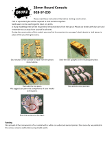
Aileron Horns
The aileron horns are bent in a
steel jig by hydroulic power.
However, due to variations in
spring tension in the wire, there
may be slight variations in the horn
angle. Set the pair of horns side by
side, as shown in the photo. If one
is not bent as far as the other, give
it a twist forward, using two pair of
pliers. Careful! It is easy to
overbend.
51.
Glue the brass tube bearings on the
back of the wing with epoxy glue.

.
52. Epoxy the pieces of trailing edge stock
over the aileron horn, taking care not to
get glue on the horn itself. It is a good
idea to put a film of vaseline on the horn
(not the bearing - which should stick to
the wood) to prevent sticking.
INSTALLING EASY HINGES
Using a No.11 X-Acto blade (or similar) cut a slot approximately 1/2" in depth
and slightly wider than the hinge. After all slots have been cut, insert an Easy
Hinge halfway into each slot in one of the pieces to be hinged. Then carefully
slide the matching model part onto the other half of the hinges. You'll find it
easiest to slide the part onto the hinges at an angle, one hinge at a time.
At this point the surface to be hinged is attached but not glued. Align the two
surfaces and adjust the gap between them as required. For best control
response, the gap should be as small as possible but big enough to allow the
control surface to move to the maximum deflection that you will require.
Place three or four drops of any brand of cyanoacrylate adhesive (thinnest
variety) directly onto the Easy Hinge in the gap. You will notice that the glue is
quickly wicked into the slot as it penetrates both the wood and the hinge.
Continue this process, gluing the same side of all of the hinges. Then turn the
surfaces over and repeat the gluing process on the other side of each hinge.
After the glue has cured, approximately three minutes, the joint can be flexed.
You may notice a slight stiffness in the joint. This can be eliminated by flexing
the surface to full deflection each direction a couple of dozen times. Don't
worry about shortening the life of the hinge as they are almost indestructible.
53.
a. Draw a centerline on the front of the 5/16"x1-1/8" shaped aileron stock and shaping lines on top and bottom, as
indicated on the cross-section drawing.
b. Carve and sand the front of the aileron stock to shape, so that it can move up and down without bumping the
aileron. (Check before gluing in place.)
c. Slot the aileron to receive the aileron horn wire.
d. Drill a 3/32" hole in the aileron to take the arm of the aileron horn wire.
NOTE: At this point it is best to apply the fiberglass tape to the wing center joint (see below) and cover both the wing and
the ailerons (see the Covering and Finishing instructions). Covering the parts separately is particularly advisable in the
case of plastic film covering so that you have access to the edges of the parts with your iron.

.
54.
a. Cut the hinge slots in the wing and ailerons to accept the Easy Hinges.
(See above for detailed information on installing the hinges.) Don't apply
glue to the hinges yet! Trial fit the ailerons to-be certain they are ready for
permanent installation on the wing.
b. Put a 1-1/2" wide strip of wax paper about 3" long, between the wing and
the aileron horn wire to keep the glue that is put into the aileron from being
squeezed onto the wing during assembly. Apply 5-minute epoxy to the slot
and hole in the aileron. Slide the aileron onto the horn and the hinges all at
the same time. Check the positioning of the aileron before the glue sets to
be certain it is located properly.
c.
Just before the glue sets up, pull the ends of the strip of wax paper over the
horn wire, squeezing the glue into a rounded shape and forming a skin
over the wire. After the glue stiffens, any excess that is squeezed up over
the aileron can be picked or trimmed off before it is fully cured.
d. Apply thin CA glue to the hinges as described in the Hinging Section.
APPLYING THE FIBERGLASS WING CENTER TAPE
a. Cut strips of 2" tape for the top and bottom of the wing center joint.
b. Coat the wing center section with epoxy glue, about 1-1/4" on each side of the joint, and lay the tape
on top of the glue.
c. Holding one end of the tape so it won't slip, "squeegee" the glue through the tape, with a small paddle
made from a scrap of balsa. Scrape over the tape several times with the squeegee paddle to smooth
the tape and remove excess glue.
NOTE: Glue a piece of
thin scrap plywood or
plastic on the trailing
edge at the point the
wing rubber bands go
over the edge to keep
them from cutting into
the wing. This should
be done after covering.

.
FUSELAGE CONSTRUCTION
Different engine brands vary considerably in the distance from their mounting lugs to the needle valve body (spraybar) in
the carburetor. The ideal location for the fuel tank is to have the center line of the tank about 1/4" to 3/8" below the needle
valve body. This position helps provide a reliable idle when the fuel tank is nearly empty and less change in mixture as the
fuel level drops.
A 10 oz. tank is shown on the plan for those who wish to have long flight duration with large engines. We believe the
Sullivan RST 8 oz. tank is the best size for the average Kadet flier and this is the size we provide in the Kadet accessory
kit (available at extra cost).
Beginners find that the concentration and tension of learning to fly is tiring if a flight is prolonged much beyond 7 or 8
minutes. Some flight instructors feel that skills are developed better in shorter flights of 5 or 6 minutes. And novices often
find that 5 minutes can seem twice as long. Therefore, we recommend that a 10 ounce tank be used only on .35 and .40
sized engines. Even with these engines, an 8 ounce tank will give satisfactory flying time. The typical flight with the Kadet
is done with the motor partly throttled so long runs per ounce of fuel are usual. A .40 will run over 10 minutes on 8 ounces,
a .35 more than 12 minutes.
Measure the distance called "X" on the accompanying drawing from the engine
you will be using. For example, let's assume that distance "X" turns out to be 1". If
this engine were used in a model with no downthrust, then the engine thrust line
would also be the fuselage datum line. But, since the Kadet MK II has downthrust
incorporated into the fuselage construction, the engine will actually be
approximately 3/32" lower than 1" in the area of the needle valve, so this must be
taken into account.
Subtract 3/32" from measurement "X" to produce measurement "Y" or in our
example, 29/32".
To find the hole center measurement "Z"
for a 10 oz. Sullivan tank cap hole in the
fIrewall, subtract 1/4" to 3/8" from "Y".
Example:
1" (X) - 3/32" = 29/32" (Y) -
1/4" to 3/8" =
21/32" (Z). Place the hole center for the
10 oz. tank 21/32" to 17/32" above the
horizontal datum line of the firewall.
NOTE:
The builder does not have to do anything about measuring or incorporating the downthrust. Just use the printed parts
furnished and it is automatically built in as you construct the fuselage.
The highest that the tank hole center can be placed for a 10 ounce RST tank without fuselage modification is 3/4" above
the horizontal datum line. (The top of the tank will then be touching the center stringer of the fuselage.)
The highest that the tank hole center can be placed for an 8 ounce RST tank without fuselage modification is 7/8" above
the horizontal datum line. It is unlikely that any standard engine would require it to be any higher than this, but if so it could
be raised 3/16" higher by leaving out the center 3/16" stringer of the top or by cutting a notch into it.
Use Sullivan RST tanks with the wide side down. Don't use the "vent bubble" molded into the narrow side. It is not
necessary for good operation of the tank. The height of the 10 oz. RST is 2-1/8" so the tank centerline is 1-1/4" below the
tank top. The 8 oz. centerline is 15/16" below the tank top. When using the recommended 8 oz. Sullivan RST tank it is
possible to raise it higher in the fuselage when required by a high needle valve location than can be done with a 10 oz.
However, since we are working with the centerline on both sides, the dimension "Z" will be the same for either tank.
Once the datum lines and location of the tank hole have been drawn on the front of F-IA, proceed with the firewall
assembly as detailed in the following paragraphs.

.
TIPS ON TANKS
We occasionally receive suggestions from builders that a removable hatch be
designed into the model for access to the gas tank. Our opinion is this is not
the best method in most cases. The hatch opening makes the nose weaker
and there is no good way to keep oil leaking in around the hatch. A method of
fastening has to be built into the fuselage to hold a hatch in place.
Modern plastic tanks are virtually indestructable under normal use and
bursting or cracking is almost unknown. If you use Sig Heat Proof Silicone
tubing (which will not harden or deteriorate in fuel) in the plastic tank, the tank
will seldom have to be removed. We have models in which tank has been
installed for three or four years without ever needing removal. So it is quite
practical to put the tank in semi-permanently. Check the models at a contest -
you'll find that the majority have sealed noses, as does this kit.
Read this before you drill the 1" hole in the firewall.
Some fliers prefer not to bring the tank cap through the firewall as is shown in the construction sequence in these
instructions. Instead they drill two holes for the vent tubes only and make the vent tubes long enough to extend through
the firewall. This method requires little sealing but it is more difficult to install and remove the tank. The best way to
manage this is to feed long pieces of fuel line through the holes and attach them to the tank in the cabin area. Steer the
tank into the nose as the tubes are pulled back through the holes. If you are undecided as to which method you should
use, our advice is that large hole installation shown in the construction pictures is the best for beginners.
Put scrap wood supports under and at the back of the tank. The front is supported by the 1/4" hole in the firewall. Seal
the tank cap in the hole with G.E. Silicone Bathtub Seal (available at hardware stores) or Devcon Seal-It. Put an oil-proof
finish on the firewall and in the hole before sealing the tank cap. Get some of the sealer on the sides of the hole and also
put a bead over the edge of the cap at the front. Should you need to remove the tank, break out the scrap wood
supports in the rear and push out the silicon rubber seal around the front cap. Reach into the fuselage and guide the
tank outside.
Some builders, after putting their receiver battery in a plastic sack, taping it shut, wrapping it in a foam rubber package
and stuffing it into the nose under the tank, then stuff paper toweling or foam rubber in to fill the nose compartment and
keep everything firmly in place.

.
After installation, put fuel tubing on the vent tube and run it to the outside of the cowling on the bottom, so that fuel
overflow is not blown over the wing-fuselage joint, where it may leak into the fuselage. The best way to fill the tank is to
take off the fuel line to the needle vlave and pump the fuel in there until it runs out the vent. Be sure and use a filter on
your fuel supply can, and it is a good idea to have a filter between the tank and the needle valve also.
Pressure Feed
If the engine you are using is equipped with a muffler pressure tap, make use
of it for a more even fuel feed and reliable operation. The hookup for pressure
feed is shown in the picture. To fill the tank, remove the fuel line from the
engine and pump the fuel in. When the tank is full, it will overflow through the
muffler pressure line. Use transparent or translucent fuel line so you can see
the fuel starting to overflow when the tank is full. Should some fuel happen to
get in the muffler, drain it out before starting the engine. Do not try to fill the
tank in reverse from the pressure line, the tank will not fill properly and fuel
may be forced into the engine.
Firewall Assembly
55.
a. Smooth and even F-IA and F-IC with the sandpaper block.
b. Glue them together with epoxy glue as shown in the accompany drawing
to make the firewall. If they should be warped, clamp them together with
"c" clamps or put the assembly in a vise while the glue is setting
c. Mark the vertical and horizontal datum line.
56.
Place the motor you will use on the firewall and draw lines as a guide for
positioning the glass-filled motor mounts. (Different motors have different
mounting dimensions.)
57.
a. Line up the marks on the side of the mount with the horizontal line you
have drawn on the firewall as shown in photo 57.
NOTE: Read "Tips On Tanks" before cutting out a tank hole.
58.
a.
Locate the center of the tank cap
hole and draw a 1" circle on the
wood.
b. Drill a series of holes on the
inside of the circle.
59.
Break out the wood and sand the edges
smooth with sandpaper wrapped
around a dowel.
60.
a. Drill out the motor holes on the firewall with a 11/64" drill bit for the 6-32 blind nuts.
b.
Position the nylon nose gear bearing on the firewall, punch the holes with an ice pick or awl and drill out with a 7/64"
bit to pass the 4-40 bolts.
c. Turn the firewall over and drill out the backs of the 7/64" nosegear bearing holes with a bit to take the shanks of the
4-40 blind nuts. To complete the holes, take a modeling knife and round off the edges on the back of the firewall so
that the rounded off part of the blind nut will fit down into the hole when it is pulled tight against the firewall.
d.
Drill out the backs of the motor mount holes with a bit to take the shanks of the 6
-
32 blind nuts.

.
61. Be sure and epoxy the blind nuts to the back of the firewall so they will not come
out later when it may be necessary to take off the mounts. Don't get epoxy into
the threads of the bolts. Pull the blind nut points tight into the wood with the bolts
before the glue sets up.
With the mounts and nose gear bracket in place, cut off the mounting bolts for
both flush with the face of the blind nuts on the back of the firewall. This is to
prevent any chance of the bolt ends puncturing the tank or rubbing on the
batteries.
62.
a. Put the spinner backplate that will be used on the motor. (Note: Some
backplates have a recess in the back as does this Goldberg spinner used
on the prototype Kadet Mark II. This is why the measurement must be
taken from the spinner backplate itself and not the prop drive washer on
the motor.
b. Position the motor on the mounts so the spinner backplate will be 3 1/2"
from the face of the firewall. It is handy to tack the motor in position with
some spots of epoxy, brought up over the edge of engine to grip it good or
put a strip of double-faced masking tape between the engine and the
mounts. This will keep it from slipping during the next step.
63.
NOTE: Read "Cowling Installation" at step 124
Mark the engine mounting holes as shown in photo #63. Remove the engine, and mounts from the
firewall, and drill at the marks with a bit that's just large enough to clear your engine mounting
bolts. (Hint: if you are not used to doing this sort of job, don't try to punch and drill all 4 holes at
once. Punch and drill only one hole. Then put the motor back on the mounts, secured by the first
bolt. Punch and drill a 2nd hole, repeat the procedure, then a third hole, etc. With this process you
are much less likely to make a drilling mistake that will ruin the mounts.) Drilling our mounts will
not be a problem if a good quality high-speed drill bit is used, operated at neither too fast or too
slow a speed and with moderate pressure.
Re-install the motor mounts to the firewall, then bolt the engine in place. SIGSH109 6-32x3/4" socket head bolts for long
engines and SIGSH652 Aircraft Lock Nuts, or SIGSH104 4-40 x 3/4" and SIGSH651 Aircraft Lock Nuts for small engines
are recommended for mounting. They are not furnished in this kit. It helps with this method to file a flat place on the bottom
of the mount, so the locknut will set flush with the bottom of the mount.
NOTE: If the fuselage sizes are bowed or warped, it will not be a problem. Pinning them down to a flat building board and
gluing on the structure will flatten them out.
64.
a. Drill or cut out the dowel holes in the fuselage sides so that they will be located after the inner doubler is installed.
b. Trim off the fuselage sheet even with the back end of the fuselage and glue the rear fuselage extension in place.
Use a straight edge to make certain it is lined up straight with the rest of the fuselage side.
65.
Glue on the 1/4" sq. balsa pieces around the edges of the fuselage sides as indicated on the printed sheets. Also cut and
glue the 1/4"x1/2" balsa strip located under the wing.

.
66. a. Pin and glue pieces of 1/8" x 3/8" balsa in place.
b. Note the gap left for F-3.
c. Glue die cut Lite-Ply nose doubler FN on the nose.
CAUTION: Epoxy is recommended for FN. Water base glues such as Sig Bond,
Tite Bond, Elmer's etc. may cause curling because of the large area being glued.
Spread a thin film of epoxy with a paddle. Don't use a large amount of glue - it will
add weight to the model.
67.
a. The balsa cabin doublers are cut
from 1/8" x 3" sheet. (Note:
Because sheet wood varies in
actual width, the dotted lines
printed on the fuselage side may
not line up exactly with the
sheets. It makes no difference -
just install the sheets butted
against each other.
b. A gap is left for cabin former F-3.
68.
a. Glue the 1/4"x1/2" balsa strip at
the end of the second 1/8"
doubler sheet piece.
69.
a. Continue on back, adding pieces
as indicated.
b. Leave a gap for F-4.
70.
a. Cut the 1/4" sq. balsa side stiffeners a little overlength and finish to an
exact fit using a sanding block. Always try for good joints without gaps -
they are stronger than trusting the glue to fill the gap. If you have a perfect
fit, you can use thin CA to glue the parts; otherwise, use medium CA. Slow
CA or epoxy will fill gaps in an emergency, but remember those joints will
be heavier than joints made with thin CA or Sig-Bond.
b. Cut FB out of the printed tail parts sheet.
71.
Glue the parts in place.
72.
Cut the fuselage sides from the sheet with a modeling knife. Don't cut too close, leave a bit for sanding, cutting too close
can result in too deep a cut that is harder to fix than taking down the side a little with the sanding block.
73.
Finish the side to exact contour by use of the sanding block. Place the two sides together and match them by sanding as
required to make them duplicates.

.
74.
Add DCF and DC.
75.
Put 5 minute epoxy on F3 and glue in place on one of the sides. As the glue sets up, use a triangle to get F3 exactly
perpendicular. Other glue can be used if you secure the former in place while it is drying.
76.
Repeat the procedure with F
-
4.
77.
Pin the fuselage side to the top view plan along the flat part between the nose and the landing gear plate position.
78.
Epoxy glue the remaining side to F3 and F4. Pin in place and check for square with a triangle.
79.
The bottom at the rear is joined with a piece of scrap 3/32" sheet. (It is shown here after being glued in and dry. Don't take
up the fuselage from the plan to put this piece in, but fit it in from above before the top crosspiece is put in.)
80.
a. Pull the rear end together by using square weights or something similar (pieces of scrap iron shown here) that is
perpendicular and yet heavy enough not to move.
b.
Pin and glue the rear cross pieces in place.
81.
Glue in the four remaining 1/4" sq. balsa rear fuselage cross pieces.
82.
Use pins and masking tape to hold the rear fuselage together until the glue dries.
83.
a. Drill through the 1/4"x1/2" balsa strip.
b.
Trial fit the 1/4" dia.x5
-
1/4" rear hold
-
down dowel, but don't glue it in place until after covering.
/