Page is loading ...

INSTALLATION INSTRUCTIONS
AND USER MANUAL
RESIDENTIAL USE ONLY
INSTALLER : LEAVE THIS MANUAL WITH CONSUMER.
HOMEOWNER : USE AND CARE INFORMATION
ON PAGES 24 to 31.
READ AND SAVE THESE INSTRUCTIONS
05438 rev. 08
MODELS
HEPA 3.2* and THH 1.0*
VB0049
VB0058
*Patents pending
NOTE : HEPA 3.2 model available in Canada only.

ABOUT THIS MANUAL
First, we want to congratulate you on your purchase of this excellent unit which will allow you and your family to enjoy clean and healthy
air throughout your home for years to come!
The illustrations in this publication are typical ones. Some details of your unit may be slightly different than the ones shown.
Please take note that this manual uses the following symbols to emphasize particular information :
NOTE: Indicates supplementary information needed to fully complete an instruction.
We welcome any suggestions you may have concerning this manual and/or the unit, and we would appreciate hearing your comments
on ways to better serve you. Please contact us at the address listed in the warranty text, at the end of this manual.
WARNING
Identifies an instruction which, if not followed, might cause serious personal injuries including possibility of death.
CAUTION
Denotes an instruction which, if not followed, may severely damage the unit and/or its components.
- 2 -
ABOUT THESE UNITS
WARNING
TO REDUCE THE RISK OF FIRE, ELECTRIC SHOCK, OR INJURY TO PERSON(S) OBSERVE THE FOLLOWING :
1. This unit is intented for residential installation only.
2. Installation must be done in accordance with all applicable codes and standards, including fire-rated
construction codes and standards.
3. This unit is not designed to provide combustion and/or dilution air for fuel-burning appliances.
4. Do not install in a cooking area or connect directly to an appliance.
5. Before replacing filters, servicing or cleaning unit, disconnect the power cord from electrical outlet.
6. When cutting or drilling into wall or ceiling, do not damage electrical wiring or other hidden utilities.
7. Do not use this unit with any solid-state speed control device other than wall controls no. 04862 or no. 05439
(for HEPA 3.2 unit) and no. 04391, no. 05536 , Altitude or Platinum (for THH 1.0 unit) (all control devices sold
separately).
8. This unit must be grounded. The power supply cord has a 3-prong grounding plug for your personal safety. It
must be plugged into a mating 3-prong grounding receptacle, grounded in accordance with the national electrical
code and local codes and ordinances. Do not remove the ground prong. Do not use an extension cord.
9. This unit must be installed in a weatherized location out of direct sunlight and protected from the elements.
10. Use this unit only in the manner intended by the manufacturer. If you have questions, contact the manufacturer
at the address or telephone number listed in this document.
11. For general filtration and ventilation use only. Do not use to exhaust hazardous or explosive materials
and vapors.
12. When performing installation, servicing or cleaning the unit, it is recommended to wear safety glasses and gloves.
13. When applicable local regulations comprises more restrictive installation and/or certification requirements,
the aforementioned requirements prevail on those of this document and the installer agrees to conform to
these at his own expenses.
CAUTION
1. Intended for residential installation only in accordance with the requirements of NFPA 90B.
2. Do not run any air ducts directly above or closer than 2 ft (0.61 m) to any furnace or its supply plenum, boiler,
or other heat producing appliance.
2.1 For HEPA 3.2 unit only
, if a duct has to be connected to the furnace return plenum, it must be connected
not closer than 2 ft (0.61 m) from this plenum connection to the furnace.
2.2 For THH 1.0 unit only
, if a duct has to be connected to the furnace return plenum, it must be connected
not closer than 9’10” (3 m) from this plenum connection to the furnace.
3. The ductwork is intended to be installed in compliance with all applicable codes.
4. To avoid premature clogged filters, turn OFF the unit during construction or renovation.
5. Please read the unit specification label on the product for further information and requirements.
!
!

1. TECHNICAL DATA . . . . . . . . . . . . . . . . . . . . . . . . . . . . . . . . . . . . . . . . . . . . . . . . . . . . . . .4
1.1 PERFORMANCE CHARTS . . . . . . . . . . . . . . . . . . . . . . . . . . . . . . . . . . . . . . . . . . . . . . . . . . . . . . . . . . . . . .4
1.2 SPECIFICATIONS . . . . . . . . . . . . . . . . . . . . . . . . . . . . . . . . . . . . . . . . . . . . . . . . . . . . . . . . . . . . . . . . . . . .4
1.3 D
IMENSIONS . . . . . . . . . . . . . . . . . . . . . . . . . . . . . . . . . . . . . . . . . . . . . . . . . . . . . . . . . . . . . . . . . . . . . . .5
1.4 MOUNTING AND SERVICING CONSIDERATION . . . . . . . . . . . . . . . . . . . . . . . . . . . . . . . . . . . . . . . . . . . . . . . .5
2. HEPA 3.2 UNIT INSTALLATION OVERVIEW . . . . . . . . . . . . . . . . . . . . . . . . . . . . . . . . . .6
3. THH 1.0 UNIT INSTALLATION OVERVIEW . . . . . . . . . . . . . . . . . . . . . . . . . . . . . . . . . . .7
4. UNIT INSTALLATION . . . . . . . . . . . . . . . . . . . . . . . . . . . . . . . . . . . . . . . . . . . . . . . . . .8-19
4.1 INSPECT THE CONTENT OF THE BOX . . . . . . . . . . . . . . . . . . . . . . . . . . . . . . . . . . . . . . . . . . . . . . . . . . . . . .8
4.2 LOCATING AND MOUNTING THE UNIT . . . . . . . . . . . . . . . . . . . . . . . . . . . . . . . . . . . . . . . . . . . . . . . . . . . . . .8
4.3 M
OUNT THE PORTS ON THE UNIT . . . . . . . . . . . . . . . . . . . . . . . . . . . . . . . . . . . . . . . . . . . . . . . . . . . . . . . .8
4.4 MOUNT THE NAMEPLATE ON THE UNIT . . . . . . . . . . . . . . . . . . . . . . . . . . . . . . . . . . . . . . . . . . . . . . . . . . . .8
4.5 HOW TO HANG THE UNIT . . . . . . . . . . . . . . . . . . . . . . . . . . . . . . . . . . . . . . . . . . . . . . . . . . . . . . . . . . .9-10
4.6 P
LANNING OF THE HEPA 3.2 DUCTWORK . . . . . . . . . . . . . . . . . . . . . . . . . . . . . . . . . . . . . . . . . . . . . . . . .11
4.7 CALCULATING THE HEPA 3.2 DUCT SIZE . . . . . . . . . . . . . . . . . . . . . . . . . . . . . . . . . . . . . . . . . . . . . . . . .11
4.8 PLANNING OF THE THH 1.0 DUCTWORK . . . . . . . . . . . . . . . . . . . . . . . . . . . . . . . . . . . . . . . . . . . . . . . . . .12
4.9 CALCULATING THE THH 1.0 DUCT SIZE . . . . . . . . . . . . . . . . . . . . . . . . . . . . . . . . . . . . . . . . . . . . . . . . . .12
4.10 I
NSTALLING DUCTWORK AND REGISTERS . . . . . . . . . . . . . . . . . . . . . . . . . . . . . . . . . . . . . . . . . . . . . . .13-15
4.11 INSTALLING INSULATED FLEXIBLE DUCT (THH 1.0 UNIT ONLY) . . . . . . . . . . . . . . . . . . . . . . . . . . . . . . . .15-17
4.12 INSTALLING DUAL EXTERIOR HOOD (THH 1.0 UNIT ONLY) . . . . . . . . . . . . . . . . . . . . . . . . . . . . . . . . . . .17-18
4.13 C
ONNECTING THE DRAIN (THH 1.0 UNIT ONLY) . . . . . . . . . . . . . . . . . . . . . . . . . . . . . . . . . . . . . . . . . . . . .19
5. CONTROLS . . . . . . . . . . . . . . . . . . . . . . . . . . . . . . . . . . . . . . . . . . . . . . . . . . . . . . . .19-23
5.1 MAIN SWITCH . . . . . . . . . . . . . . . . . . . . . . . . . . . . . . . . . . . . . . . . . . . . . . . . . . . . . . . . . . . . . . . . . . . . .19
5.2 OPTIONAL CONTROLS . . . . . . . . . . . . . . . . . . . . . . . . . . . . . . . . . . . . . . . . . . . . . . . . . . . . . . . . . . . . . .20
5.3 D
IMENSIONS . . . . . . . . . . . . . . . . . . . . . . . . . . . . . . . . . . . . . . . . . . . . . . . . . . . . . . . . . . . . . . . . . . . . . .20
5.4 INSTALLATION OF THE OPTIONAL CONTROL . . . . . . . . . . . . . . . . . . . . . . . . . . . . . . . . . . . . . . . . . . . . . .21-23
5.5 O
PERATING THE NO. 04862 OR NO. 05439 CONTROL . . . . . . . . . . . . . . . . . . . . . . . . . . . . . . . . . . . . . . . .24
5.6 OPERATING THE NO. 04391 OR NO. 05536 CONTROL . . . . . . . . . . . . . . . . . . . . . . . . . . . . . . . . . . . . . . . .24
5.7 OPERATING THE ALTITUDE OR PLATINUM CONTROL . . . . . . . . . . . . . . . . . . . . . . . . . . . . . . . . . . . . . . . .24-27
6. WIRING DIAGRAMS . . . . . . . . . . . . . . . . . . . . . . . . . . . . . . . . . . . . . . . . . . . . . . . . . . . .28
6.1 HEPA 3.2 WIRING DIAGRAM . . . . . . . . . . . . . . . . . . . . . . . . . . . . . . . . . . . . . . . . . . . . . . . . . . . . . . . . . .28
6.2 THH 1.0 WIRING DIAGRAM . . . . . . . . . . . . . . . . . . . . . . . . . . . . . . . . . . . . . . . . . . . . . . . . . . . . . . . . . . .28
7. BALANCING PROCEDURE (THH 1.0 ONLY) . . . . . . . . . . . . . . . . . . . . . . . . . . . . . . . . .29
7.1 WHAT YOU NEED TO BALANCE THE UNIT . . . . . . . . . . . . . . . . . . . . . . . . . . . . . . . . . . . . . . . . . . . . . . . . .29
7.2 PRELIMINARY STAG ES TO BALANCE THE UNIT . . . . . . . . . . . . . . . . . . . . . . . . . . . . . . . . . . . . . . . . . . . . . .29
7.3 INSTALLATION OF FLOW COLLAR . . . . . . . . . . . . . . . . . . . . . . . . . . . . . . . . . . . . . . . . . . . . . . . . . . . . . . . .29
7.4 BALANCING PROCEDURE . . . . . . . . . . . . . . . . . . . . . . . . . . . . . . . . . . . . . . . . . . . . . . . . . . . . . . . . . . . . .29
8. MAINTENANCE . . . . . . . . . . . . . . . . . . . . . . . . . . . . . . . . . . . . . . . . . . . . . . . . . . . . . .30
8.1 SEMI-ANNUAL MAINTENANCE (ESSENTIAL) . . . . . . . . . . . . . . . . . . . . . . . . . . . . . . . . . . . . . . . . . . . . . .30-31
8.2 ANNUAL MAINTENANCE . . . . . . . . . . . . . . . . . . . . . . . . . . . . . . . . . . . . . . . . . . . . . . . . . . . . . . . . . . . . . .31
8.3 MASTER RESET (EXCEPT FOR ALTITUDE OR PLATINUM WALL CONTROL) . . . . . . . . . . . . . . . . . . . . . . . . . . .31
9. PARTS ORDERING CHART . . . . . . . . . . . . . . . . . . . . . . . . . . . . . . . . . . . . . . . . . . . . . .31
10. TROUBLESHOOTING . . . . . . . . . . . . . . . . . . . . . . . . . . . . . . . . . . . . . . . . . . . . . . . .31-32
11. WARRANTY . . . . . . . . . . . . . . . . . . . . . . . . . . . . . . . . . . . . . . . . . . . . . . . . . . . . . . . . . . .32
TABLE OF CONTENTS
- 3 -

1. TECHNICAL DATA
HEPA 3.2 FILTRATION AIR FLOW
THH 1.0 VENTILATION PERFORMANCE
1.00
0.80
0.60
0.40
0.20
0.00
VG0064
100 125 150 175 200 225 250 275 300 325
1.20
High speed
(Boost mode)
Low speed
(Normal mode)
AIR FLOW (CFM)
EXTERNAL STATIC PRESSURE
(INCH OF WATER)
E
XTERNAL STATIC PRESSURE
(INCH OF WATER)
020406080 100 120
0.00
0.20
0.40
0.60
0.80
1.00
1.20
VG0065
GROSS AIR FLOW (CFM)
Low Speed
Supply
(cfm)
Exhaust
(cfm)
1.1 PERFORMANCE CHARTS
1.2 SPECIFICATIONS
- 4 -
NOTE : All specifications are subjected to change without notice.
High Speed
Supply
(cfm)
Exhaust
(cfm)
HIGH SPEED
LOW SPEED
THH 1.0 ENERGY PERFORMANCE
EXT STATIC
PRESSURE
NET SUPPLY
AIR FLOW
GROSS AIR FLOW
SUPPLY
GROSS AIR FLOW
EXHAUST
Pa in.w.g l/s cfm m³/h l/s cfm m³/h l/s cfm m³/h
50 0.2 47 100 170 50 105 178 50 106 180
100 0.4 44 93 158 46 98 165 46 99 167
150 0.6 41 86 146 42 90 155 43 91 155
200 0.8 37 79 134 39 83 141 38 80 136
250 1.0 34 73 124 36 76 129 33 71 121
EXT STATIC
PRESSURE
NET SUPPLY
AIR FLOW
GROSS AIR FLOW
SUPPLY
GROSS AIR FLOW
EXHAUST
Pa in.w.g l/s cfm m³/h l/s cfm m³/h l/s cfm m³/h
50 0.2 23 48 82 24 51 87 26 54 92
100 0.4 21 45 76 23 48 82 23 49 83
150 0.6 19 40 68 20 43 73 19 41 70
SUPPLY
TEMPERATURE
NET AIR FLOW
POWER
CONSUMED
WATTS
SENSIBLE
RECOVERY
EFFICIENCY
APPARENT
SENSIBLE
EFFECTIVENESS
°C °F l/s cfm m³/h
HEATING
0 +32 24 52 87 116 63 85
0 +32 35 74 126 147 59 75
0 +32 44 94 158 189 57 75
-25 -13 16 35 59 114 58 95
COOLING
TOTAL RECOVERY EFFICIENCY
+35 +95 — — —
Not Tested
+35 +95 — — —
Model HEPA 3.2 THH 1.0
Weight 34 lb (15.4 kg) 41.2 lb (18.7 kg)
Performance 180 cfm low speed
320 cfm high speed
50 cfm low speed
90 cfm high speed
Oval Ports fit two 8” round ducts fit four 5” or 6” round ducts
Installation : Suspension 4 Chains, springs and hooks (included with the unit)
Electrical Supply 120 Volts AC, 60 Hz
Power Consumption ("Boost") 170 Watts 192 Watts
Power Consumption ("Normal") 105 Watts 110 Watts

- 5 -
1. TECHNICAL DATA (CONT’D)
1.3 DIMENSIONS
HEPA 3.2 THH 1.0
FRONT VIEW TOP VIEW FRONT VIEW TOP VIEW
17.8''
(452 mm)
29''
(737 mm)
22.9'' (581 mm)
VK0047A
17.8''
(452 mm)
30.2''
(767 mm)
22.9'' (581 mm)
VK0049A
1.4 MOUNTING AND SERVICING CONSIDERATIONS
• The two following pictures are showing the minimum clearance needed to open the door completely.
22.5” 15.75”
(572
MM) (400 MM)
VD0117
VD0116
22”
(559
MM)
NOTES :1. A minimum of 8” (203 mm) clearance from any obstruction on top of the unit is required for the ductwork radius turn.
2. A grounded three-prong electrical outlet has to be available within 3 feet from the unit.
8”
(203
MM)

2. HEPA 3.2 UNIT INSTALLATION OVERVIEW
VH0038
INSTALLATION TYPE SHOWN : CENTRAL DRAW POINT
SEE SECTION 4.10.2
STAND ALONE INSTALLATION
SEE SECTION 4.10.1
RETURN-RETURN INSTALLATION
SEE SECTION 4.10.3
HOW TO HANG THE UNIT
SEE SECTION 4.5
SECTION 5 : CONTROL
PLANNING OF THE HEPA 3.2
DUCTWORK, DUCT SIZE,
SEE SECTIONS 4.6 AND 4.7
VH0037
VH0047
VD0129
VC0054
- 6 -
VI0013

3. THH 1.0 UNIT INSTALLATION OVERVIEW
VH0040
INSTALLATION TYPE SHOWN : CENTRAL DRAW POINT
SEE SECTION 4.10.2
STAND ALONE INSTALLATION
SEE SECTION 4.10.1
RETURN-RETURN INSTALLATION
SEE SECTION 4.10.3
HOW TO HANG THE UNIT
SEE SECTION 4.5
CONNECTING THE DRAIN
SEE SECTION 4.13
SECTION 5 : CONTROL
VH0039
VH0043
VD0150
VO0029
VC0054
PLANNING OF THE THH 1.0
DUCTWORK, DUCT SIZE,
SEE SECTIONS 4.8 AND 4.9
VI0011
- 7 -
VD0149
OUTDOOR CONNECTION
SEE SECTIONS 4.11 AND 4.12

4
.1 INSPECT THE CONTENT OF THE BOX
• Inspect the exterior of the unit for shipping damage. Ensure there is no damage to the door, door latches, main switch, etc.
• Inspect the interior of the unit for damage. Ensure the blower assembly, insulation, prefilter, HEPA filter, heat recovery core
(THH 1.0 unit only), etc. are all intact.
• If the unit was damaged during shipping, contact your local distributor.
4.2 LOCATING AND MOUNTING THE UNIT
Choose an appropriate location for the unit.
• Within an area of the house where the ambient temperature is between 10°C (50°F) and 30°C (86°F) (basement, furnace room,
closet, etc.).
• So as to provide easy access to the interior of the unit, for filter maintenance.
• Away from hot chimneys and other fire hazards.
• Close to an exterior wall, so as to limit the length of the insulated flexible duct to and from the unit (THH unit only).
• Close to a drain. If no drain is close by, use a pail to collect run-off (THH unit only).
4.3 MOUNT THE PORTS ON THE UNIT
Mount the oval ports on the top of the unit using the screws provided in the hardware box (4 screws no. 8 x 3/4” long per port, 8” oval
ports for HEPA 3.2 unit and 5” to 6” oval ports for THH 1.0 unit).
HEPA 3.2 THH 1.0
NOTE : If an optional control has to be installed, do not install
the front oval port (1) at this time.
4.4 MOUNT THE NAMEPLATE ON THE UNIT
Select your company nameplate (Venmar or vänEE) and snap it on the unit door. Discard the
other nameplate.
CAUTION
Remove the cardboard strip inside the unit (if applicable).
WARNING
To avoid risk of suffocation, discard the plastic bag wrapping the unit.
!
VO0045
1
VO0060
1
4. UNIT INSTALLATION
VO0049
- 8 -

• Using a screwdriver, remove the 2 retaining screws of the front plate and carefully remove
the front plate from the unit.
4.5 HOW TO HANG THE UNIT
Use the 4 chains and springs in the hardware pack provided with the unit. According to your needs, you can install the unit either in vertical
or horizontal position.
4. UNIT INSTALLATION (CONT’D)
THH 1.0 UNIT ONLY
VD0129
VERTICAL POSITION
VD0130
VD0131
HORIZONTAL POSITION (LEFT SIDE)HORIZONTAL POSITION (RIGHT SIDE)
HEPA 3.2 UNIT ONLY
VD0150
CAUTION
Always install the unit vertically (with ports on top). Make sure the unit is level.
Use the 4 chains and springs in the hardware pack provided with the unit.
ALL UNITS
• Turn the switch knob to OFF position in order to unlock the door. Unlatch the door and open it.
NOTE : If preferred, the door can be removed. First, remove the stopper (A) located on the
right side of the door hinge, then, slide the door out of its hinge.
VD0170
A
VO0019
- 9 -

4. UNIT INSTALLATION (CONT’D)
4.5 HOW TO HANG THE UNIT (CONT’D)
•
Insert the 4 hooks in the square holes and fix them to the unit using 4 screws no. 8 - 32 x 3/4”.
NOTE : If an optional control has to be installed, go to Section 5 on pages 19 to 23.
If not, continue the installation.
• Reinstall the front plate, the door and the door stopper.
• Hang the unit to the floor joist, using 4 no. 8 x 1½” screws, 4 chains and 4 springs. See illustrations below.
HEPA 3.2 THH 1.0
VO0020
- 10 -
VD0132
VD0151

4. UNIT INSTALLATION (CONT’D)
NOTE : Examples 4.7.1 and 4.7.2 use imperial measures. The same calculation applies to metric measures.
4.7.1 EXAMPLE OF CALCULATION :
Problem : My installation requires two exhaust registers (one for the kitchen, one for the living
room). I will connect these registers to a main duct which will connect to the unit (high
speed performance value of 320 cfm). What size of duct should I use for the main
exhaust duct and for the two end branches leading to the registers?
(See illustration beside.)
Solution : Simplified method. (For a more detailed method of calculating duct size refer to the
ASHRAE or HRAI HANDBOOK).
Main duct :
Table above indicates a 8” Ø : recommended air flow : 260 cfm; maximum
air flow : 380 cfm. The high speed air flow of 320 cfm is close enough to the recommended
value (260) and far enough of the maximum value (380). Therefore a 8” Ø duct or larger
is an appropriate choice for the main exhaust duct.
End branches : Each end branch will have to transport an air flow of 160 cfm (320
divided by 2). Table above indicates a 6” Ø : recommended air flow : 120 cfm; maximum
air flow : 180 cfm. The high speed air flow of 160 cfm is close enough to the
recommended value (120) and far enough of the maximum value (180). Therefore a 6”
Ø duct or larger is an appropriate choice for the 2 end branches
.
4.7.2 EXAMPLE OF A DESIGN FOR A FULLY DUCTED SYSTEM FOR A UNIT HAVING A HIGH SPEED PERFORMANCE OF 320 CFM.
- 11 -
VI0012
MAIN BRANCH
8” Ø 320 CFM
END
BRANCHES
6” Ø
160 CFM
VI0013
8” Ø 320 CFM
8” Ø 320 CFM
6” Ø
160 CFM
6” Ø 160 CFM
6” Ø 160 CFM
6” Ø 160 CFM
4.6 PLANNING OF THE HEPA 3.2 DUCTWORK
• Follow the instructions in Section 4.7 below to determine the appropriate duct diameters for your system. Do not use branch lines
smaller than 6” Ø (152 mm) diameter.
• Do not use wall cavities as ducts.
• Keep it simple. Plan for a minimum of bends and joints.
• Do not ventilate crawl spaces or cold rooms.
• If the house has two floors or more, be sure to plan for at least one exhaust register at the highest lived-in level of the house.
4.7 CALCULATING THE HEPA 3.2 DUCT SIZE
Use the table below to ensure that the ducts you intend to install will be carrying air flows around the recommended values.
Avoid installing ducts that will have to carry air flows near the maximum values and never install a duct if its air flow exceed
the maximum value.
CAUTION
Do not attempt to recover the exhaust air from a dryer or a range hood. This would cause clogging of the filters.
Duct
Diameter
Recommended Air Flow Maximum Air Flow
6” (152 mm) 120 cfm 57 l/s 204 m³/h 180 cfm 85 l/s 306 m³/h
7” (178 mm) 185 cfm 87 l/s 314 m³/h 270 cfm 127 l/s 459 m³/h
8” (203 mm) 260 cfm 123 l/s 442 m³/h 380 cfm 179 l/s 645 m³/h

NOTE : Examples 4.9.1 and 4.9.2 use imperial measures. The same calculation applies to metric measures.
4.9.1 EXAMPLE OF CALCULATION :
Problem : My installation requires two exhaust registers (one for the kitchen, one for the bathroom).
I will connect these registers to a main duct which will connect to the unit (high speed
performance value of 90 cfm). What size of duct should I use for the main exhaust duct
and for the two end branches leading to the registers? (See illustration beside.)
Solution : Simplified method.
(For a more detailed method of calculating duct size refer to the
ASHRAE or HRAI HANDBOOK).
Main duct :
Table above indicates a 5” Ø duct : recommended air flow : 75 cfm;
maximum air flow : 110 cfm. The high speed air flow of 90 cfm is close enough to the
recommended value (75) and under the maximum value (110). Therefore a 5” Ø duct or
larger is an appropriate choice for the main exhaust duct.
End branches : Each end branch will have to transport an air flow of 45 cfm (90 divided
by 2). Table above indicates a 4” Ø duct : recommended air flow : 40 cfm; maximum air
flow : 60 cfm. The high speed air flow of 45 cfm is close enough to the recommended value
(40) and far enough away from the maximum value (60). Therefore a 4” Ø duct or larg-
er is an appropriate choice for the 2 end branches
.
4.9.2 EXAMPLE OF A DESIGN FOR A FULLY DUCTED SYSTEM FOR A UNIT HAVING A HIGH SPEED PERFORMANCE OF 90 CFM.
4. UNIT INSTALLATION (CONT’D)
VI0010
MAIN BRANCH
5” OR ” Ø 90 CFM
4” Ø
45 CFM
VI0011
5” Ø 90 CFM
5” Ø 90 CFM
4” Ø
45 CFM
4” Ø 45 CFM
4” Ø 45 CFM
4” Ø 45 CFM
END
BRANCHES
- 12 -
4.8 PLANNING OF THE THH 1.0 DUCTWORK
• Follow the instructions in Section 4.9 below to determine the appropriate duct diameters for your system. Do not use branch lines
smaller than 4” Ø (102 mm) diameter.
• Do not use wall cavities as ducts.
• Keep it simple. Plan for a minimum of bends and joints.
• Do not ventilate crawl spaces or cold rooms.
• If the house has two floors or more, be sure to plan for at least one exhaust register at the highest lived-in level of the house.
• Keep the length of insulated ducts to a minimum.
4.9 CALCULATING THE THH 1.0 DUCT SIZE
Use the table below to ensure that the ducts you intend to install will be carrying air flows around the recommended values.
Avoid installing ducts that will have to carry air flows near the maximum values and never install a duct if its air flow exceed
the maximum value.
CAUTION
Do not attempt to recover the exhaust air from a dryer or a range hood. This would cause clogging of the filters
and the heat recovery core.
Duct
Diameter
Recommended Air Flow Maximum Air Flow
4” (152 mm) 40 cfm 19 l/s 68 m³/h 60 cfm 28 l/s 102 m³/h
5” (178 mm) 75 cfm 35 l/s 127 m³/h 110 cfm 52 l/s 187 m³/h
6” (203 mm) 120 cfm 57 l/s 204 m³/h 180 cfm 85 l/s 306 m³/h

4. UNIT INSTALLATION (CONT’D)
4.10 INSTALLING DUCTWORK AND REGISTERS
4.10.1 STA ND ALONE SYSTEM
Stale air exhaust ductwork
WARNING
Never install a stale air exhaust register in a closed room where a combustion device operates, such as a gas
furnace, a gas water heater or a fireplace.
!
• Install the stale air exhaust registers in the areas where the contaminants are produced : kitchen, living room, etc. Position the
register as far from the stairway as possible and in such a way that the air circulates in all the lived-in spaces in the house.
NOTE : For HEPA 3.2 unit only, never install a stale air exhaust register in a bathroom.
• If a register is installed in the kitchen, it must be located at least 4 feet (1.2 m) from the range.
• Install the registers at 6 in. to 12 in. (152 mm to 305 mm) from the ceiling on an interior wall OR install it in the ceiling.
• Use the provided red sticker dots to identify the duct.
Filtered air distribution ductwork
• Install the filtered air distribution registers in the lowest level to ensure the greatest possible air circulation. Keep in mind that the
filtered air registers must be located as far as possible from the stale air registers.
• Install the register in the ceiling OR at 6 in. to 12 in. (152 mm to 305 mm) from the ceiling on an interior wall. The duct length should be at
least 15 feet (4.6 m). (The filtered air will then flow through the room and mix with room air, ensuring a continuous recirculating air flow.)
• Use the provided blue sticker dots to identify the duct.
How to connect the flexible duct to the HEPA 3.2 unit ports
• Each port is identified on top of the unit (see illustrations below). Attach the filtered air to building duct to its corresponding port,
using tie wrap (1). Then, attach the exhaust air from building duct to the other port (2).
NOTE : Use a 8’’ insulated duct if the duct will have to go through extreme temperature (e.g.: in northern area, not heated attic in
winter or attic not cooled in southern area). Also, if you plan to stop the unit for more than 12 hours, we recommend to
cover the duct with R12 insulation.
How to connect the flexible duct to the THH 1.0 unit ports
• Each port is identified on top of the unit (see illustrations below). Attach the fresh / filtered air to building duct to its corresponding
port, using tie wrap (1). Then, attach the exhaust air from building duct to the other port (2).
NOTE : Use a 5’’ or 6’’ insulated duct if the duct will have to go through extreme temperature (e.g.: in northern area, not heated attic
in winter or attic not cooled in southern area). Also, if you plan to stop the unit for more than 12 hours, we recommend to
cover the duct with R12 insulation.
VO0047
VO0048
12
VO0061
VO0062
12
- 13 -

• Attach this duct to the
FRESH AIR TO BUILDING
port (see icon
on the top of the unit), using tie wrap and duct tape. Use
the provided blue sticker dots to identify the duct.
• Locate the opening for the filtered air ductwork (HEPA 3.2
unit) or fresh/filtered air ductwork (THH 1.0 unit) on the
furnace/air handler return duct at a minimum linear
distance of 2’ (0.61 m) upstream (return side : A+B+C).
4.10 INSTALLING DUCTWORK AND REGISTERS (CONT’D)
4.10.2 C
ENTRAL DRAW POINT
NOTE FOR THH 1.0 UNIT ONLY : For this type of installation, it is not essential that the furnace blower runs when the unit is in
operation, but we recommend it.
Filtered air (HEPA 3.2 unit) distribution ductwork (Return side connection)
4. UNIT INSTALLATION (CONT’D)
- 14 -
WARNING
When performing duct connections, always use approved tools and materials. Respect all corresponding laws
and/or safety regulations. Please refer to your local building code.
!
VD0114
A
B
C
VD0153
A
B
C
VO0047
VO0061
Stale air exhaust ductwork
Same as for Stand Alone System, described in point 4.10.1.

4. UNIT INSTALLATION (CONT’D)
4.10 INSTALLING DUCTWORK AND REGISTERS (CONT’D)
4.10.3 R
ETURN-RETURN
NOTE FOR THH 1.0 UNIT ONLY : To avoid the cross-contamination and achieve highest efficiencies, the furnace/air handler
blower must always be ON (or the unit efficiency will be affected).
Filtered air (HEPA 3.2 unit) or fresh/filtered air (THH 1.0) distribution ductwork (Return side connection)
Same as for Central Draw Point, described in point 4.10.2.
Stale air exhaust ductwork (Return side connection)
HEPA 3.2 THH 1.0
• Locate the take-off duct opening at least 3’ (0.9m) from the
filtered air (HEPA 3.2 unit) or fresh/filtered air (THH 1.0 unit)
ductwork connection. Proceed as for the filtered air
ductwork, but instead of using the blue dot sticker to identify
the duct, use the red dot.
• Attach this duct to the
EXHAUST AIR FROM BUILDING
port (see
icon on the top of the unit) using tie wrap and duct tape.
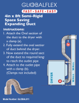
4.11 INSTALLING INSULATED FLEXIBLE DUCTS (THH 1.0 UNIT ONLY)
Use the following procedure for connecting the insulated flexible ducts to the Tandem® transition* (
EXHAUST AIR TO OUTSIDE
and
FRESH AIR FROM OUTSIDE
).
• The joist opening needed to install the Tandem transition must be 9¾” (248 mm)
minimum. Also, the maximum height of the Tandem transition is 8¾” (222 mm). See
Tandem transition end view beside.
*Patented.
NOTE : If the joists are perpendicular to the ducts, or if the connection to the exterior hood is in a limited area, your installation will
need two exterior hoods instead of one. In this case, do not use the Tandem transition. Identify each insulated duct. For
fresh air from outside duct, use the blue sticker dots (one dot at each end). For exhaust air to outside duct, use the red
sticker dots (one dot at each end). Then, go to point 4.11.2 and refer to the optional single hood enclosed instructions.
MINIMUM 3’ (0.9 M)
FROM FILTERED
AIR DUCTWORK
CONNECTION
VO0048
WARNING
When performing duct connections, always use approved tools and materials. Respect all corresponding laws
and/or safety regulations. Please refer to your local building code.
!
- 15 -
VD0154
MINIMUM 3’ (0.9 M) FROM
FRESH / FILTERED AIR
DUCTWORK CONNECTION
VO0062
CAUTION
Make sure the vapor barrier on the insulated ducts does not tear during installation.
VD0118A
8¾”
222 mm
9¾”
248 mm

4.11 INSTALLING INSULATED FLEXIBLE DUCTS (THH 1.0 UNIT ONLY) (CONT’D)
4.11.1 C
ONNECTION TO TANDEM TRANSITION
1. For each duct, pull back the insulation to expose the interior flexible duct.
2. Connect the interior flexible duct to the smaller part of the Tandem transition (5’’ oval) using a 24’’ tie wrap.
NOTE : If you are using a 6’’ diameter insulated duct, use the bigger part of the Tandem transition (6’’ oval).
3. Pull the insulation over the joint. Pull the vapor barrier over the insulation.
4. Apply duct tape gently to the joint in order to make an airtight seal
. See figures below.
Identify each insulated duct. For fresh air from outside duct, use the blue sticker dots (one dot at each end). For exhaust air to outside
duct, use the red sticker dots (one dot at each end). Be careful to identify the exhaust air to outside duct (red dot) at the upper
section of the transition.
4.11.2 CONNECTION TO THE 5’’ TO 6’’ OVAL PORTS OF THE UNIT
Use the following procedure for connecting the insulated flexible ducts to the 5’’ to 6’’ oval ports of the unit (
EXHAUST AIR TO OUTSIDE
and
FRESH AIR FROM OUTSIDE
).
1. Pull back the insulation to expose the flexible duct.
2. Connect the interior flexible duct to the smaller part of the port (5’’ oval) using a 24’’ tie wrap.
NOTE : If you are using a 6’’ diameter insulated duct, use the bigger part of the port
(6’’ oval).
3. Pull the insulation over the joint and tuck it between the inner and outer rings of the
port. Pull the vapor barrier over the insulation and over the outer ring of the port.
4. UNIT INSTALLATION (CONT’D)
VJ0025
VJ0022
VJ0023
VJ0024
1
2
3
4
- 16 -
VJ0017
VJ0016
VJ0018

4.11 INSTALLING INSULATED FLEXIBLE DUCTS (THH 1.0 UNIT ONLY) (CONT’D)
4.11.2 C
ONNECTION TO THE 5’’ TO 6’’ OVAL PORTS OF THE UNIT (CONT’D)
4. Apply duct tape gently to the joint in order to make an airtight seal.
5. Repeat steps 1 to 4 for the other 5’’ to 6’’ port.
See figure beside to find the
EXHAUST AIR TO OUTSIDE
(1)
and
FRESH AIR FROM OUTSIDE
(2) oval ports on the top of the unit.
Be careful to connect the right insulated duct to its corresponding port.
4. UNIT INSTALLATION (CONT’D)
VJ0020
1
2
VJ0019
CAUTION
Avoid compressing the insulation when you pull the tape tightly around the joint. Compressed insulation loses
its insulation properties and causes water dripping due to condensation on the exterior surface of the duct.
- 17 -
4.12 INSTALLING DUAL EXTERIOR HOOD* (THH 1.0 UNIT ONLY)
4.12.1 ASSEMBLING DUAL EXTERIOR HOOD
Exterior dual hood comes in separate parts. Using 2 no. 8 x 3/4” screws, assemble the top
metal screen and the plastic grille to the dual exterior hood. Then, slide the bottom metal
screen to the dual exterior hood. See illustration beside.
*Patented.
4.12.2 LOCATING THE DUAL EXTERIOR HOOD
The dual exterior hood must be installed at a minimum distance of 18 inches (457 mm) from the ground.
See illustration beside.
VO0024
VD0083A
18”
(457 mm)
WARNING
Make sure this hood is at least 6 feet (1.8 m) away (or more, as per applicable building codes or standards) from
sources of contamination such as :
• High efficiency furnace vent • Any exhaust from a combustion source
• Gas meter exhaust, gas barbecue-grill • Garbage bin
!

4. Snap the assembled exterior hood to its backplate and secure with 2 provided screws
(no. 8 x 3/4” long).
3. Lean the exterior backplate to the exterior wall. Using 4 no. 8 x 1½” screws, fix it to the wall.
Seal the outline with caulking.
4.12 INSTALLING DUAL EXTERIOR HOOD (THH 1.0 UNIT ONLY)(CONT’D)
4.12.3 C
ONNECTING TANDEM TRANSITION TO THE DUAL EXTERIOR HOOD
1. Using a jig saw, cut a 6’’ diameter hole in the exterior wall and insert the Tandem
transition through this hole.
1) EXHAUST AIR TO OUTSIDE DUCT
2. Joint the end of the Tandem transition to the rear of the exterior backplate. Secure
with 2 Xmas tree pins and seal properly with duct tape.
4. UNIT INSTALLATION (CONT’D)
VD0084
1
CAUTION
The Tandem transition must be inserted in such a way that the
EXHAUST AIR TO OUTSIDE
duct will be located
on the top.
VD0085
XMAS TREE PIN
CAUTION
The exterior backplate must be installed with the word “TOP” pointing upward.
- 18 -
VD0086
VD0087
SCREW

4. UNIT INSTALLATION (CONT’D)
4.13 CONNECTING THE DRAIN (THH 1.0 UNIT ONLY)
VO0140
1
VO0046
1
2
3
1.Remove the door by turning the
switch knob to the OFF position
(to unlock the door). Then, unlatch
the door and open it. Slide out the
core assembly to access the
2 drain fitting hole locations (1).
Punch out the holes.
2.Hand tighten the 2 plastic drain
fittings (1) using the gaskets (2)
and nuts (3) as shown. Close the
door.
12
VO0141A
27''
(686 mm)
7''
(178 mm)
3.Cut 2 sections of plastic tubing;
one 7’’ (178 mm) long and one
27’’ (686 mm) long, and attach
them to each drain fitting as
shown.
3
VO0142
4.Join these 2 sections to the “T’’
junction and main tube as shown.
VO0029
4
5
TIE-WRAP
TO DRAIN
5.Make a water trap loop in the
tube to prevent the unit from
drawing unpleasant odors from
the drain source. Make sure this
loop is situated BELOW the “T’’
as shown. This will prevent
water from being drawn back up
into the unit in case of negative
pressure. Run the tube to the
floor drain or an alternative drain
pipe or pail. Be sure there is a
slight slope for the run-off.
5. CONTROLS
5.1 MAIN SWITCH
These units are equipped with a 3-position main switch,
located on the front panel.
OFF :
UNIT IS OFF
AND DOOR IS
UNLOCKED
.
BOOST :
U
NIT IS OPERATING
ON HIGH SPEED.
VC0053
NORMAL/REMOTE :
UNITISOPERATINGON
NORMAL SPEED
. THIS IS
THE RIGHT POSITION
WHEN AN OPTIONAL
CONTROL IS USED.
- 19 -

5. CONTROLS (CONT’D)
5.2 OPTIONAL CONTROLS
5.3 DIMENSIONS
5.4 INSTALLATION OF THE OPTIONAL CONTROL
HEPA 3.2
no. 04862 or no. 05439
VC0054
VC0055
THH 1.0
no. 04391 or no. 05536
VC0049A
VC0105A
1"
(26 mm)
4¼" (107 mm)
4" (102 mm)
CAUTION
Failure to comply with the following can cause erratic operation of the unit :
• Never install more than one optional wall controller per unit.
• Keep control low voltage wiring at least 1 foot (305 mm) away from motors, lighting ballast, light
dimming circuit and power distribution panel. Do not route control wiring alongside house power wiring.
• Ensure the wires are securely connected.
WARNING
Always disconnect the unit before making any connections. Failure in disconnecting power could result in
electric shock or damage of the control or electronic module inside the unit.
!
- 20 -
SMART
SET
MODE
PREF
VC0100
THH 1.0
no. 40440 or no. 40460
The part number for the optional Altitude
control is 40440 (for Venmar unit) and the
part number for the optional Platinum
control is 40460 (for vänEE unit).
The optional control part
number for the THH 1.0 unit
is 04391 (for Venmar unit) or
05536 (for vänEE unit).
The optional control part
number for the HEPA 3.2 unit
is 04862 (for Venmar unit) or
05439 (for vänEE unit).
FRONT VIEW
SIDE VIEW
/