Page is loading ...

HRV110 AND ERV130
USER AND INSTALLER MANUAL
READ AND SAVE THESE INSTRUCTIONS
RESIDENTIAL USE ONLY
1107172 REV. C
Venmar Ventilation ULC, 550 Lemire Blvd., Drummondville, Québec, Canada J2C 7W9 venmar.ca 800-567-3855
VB0346
Thank you for choosing Venmar to bring fresh air inside your home.
REGISTER YOUR PRODUCT ONLINE AND
EXTEND YOUR WARRANTY BY 1 YEAR!
It is easy: Go to www.venmar.ca/register-your-product or scan the QR code
For more information, visit www.venmar.ca
YEAR!
ONE MORE

2
Please take note that this manual uses the following symbols to emphasize particular information:
Identifi es an instruction which, if not followed, might cause serious personal injuries including possibility of
death.
CAUTION
Denotes an instruction which, if not followed, may severely damage the unit and/or its components.
NOTE: Indicates supplementary information needed to fully complete an instruction.
LIMITATION
For residential (domestic) installation only. Installation work and electrical wiring must be done by a qualifi ed person in
accordance with all applicable codes and standards, including fi re-rated construction codes and standards.
⚠WARNING
TO REDUCE THE RISK OF FIRE, ELECTRIC SHOCK, OR INJURY TO PERSON(S) OBSERVE THE FOLLOWING:
1. Use this unit only in the manner intended by the manufacturer.
2. Before servicing or cleaning this unit, disconnect power cord from electrical outlet.
3. This unit is not designed to provide combustion and/or dilution air for fuel-burning appliances.
4. When cutting or drilling into a wall or ceiling, do not damage electrical wiring and other hidden utilities.
5. Do not use this unit with any solid-state speed control device other than those specifi ed in section 3.1.
6. This unit must be grounded. The power supply cord has a 3-prong grounding plug for your personal safety. It must be
plugged into a mating 3-prong grounding receptacle, grounded in accordance with the national electrical code and local
codes and ordinances. Do not remove the ground prong. Do not use an extension cord.
7. Do not install in a cooking area or connect directly to any appliances.
8. Do not use to exhaust hazardous or explosive materials and vapors.
9. When performing installation, servicing or cleaning this unit, it is recommended to wear safety glasses and gloves.
10. When applicable local regulation comprises more restrictive installation and/or certifi cation requirements, the
aforementioned requirements prevail on those of this document and the installer agrees to conform to these at his own
expenses.
CAUTION
1. To avoid prematurely clogged fi lters, turn the unit OFF during construction or renovation.
2. Please read specifi cation label on product for further information and requirements.
3. Be sure to duct air outside – Do not intake/exhaust air into spaces within walls or ceiling or into attics, crawl spaces, or
garage. Do not attempt to recover the exhaust air from a dryer or a range hood.
4. Intended for residential installation only in accordance with the requirements of NFPA 90B (for a unit installed in U.S.A.)
or Part 9 of the National Building Code of Canada (for a unit installed in Canada).
5. Do not run any air ducts directly above or within 2 ft (0.61 m) of a furnace or its supply plenum, boiler, or other heat
producing appliance. If a duct has to be connected to the furnace return plenum, it must be connected 10’ (3.1 m) away
from plenum’s connection to the furnace.
6. The ductwork is intended to be installed in compliance with all applicable local and national codes.
7. When leaving the house for a long period of time (more than two weeks), a responsible person should regularly check
if the unit operates adequately.
8. If the ductwork passes through an unconditioned space (e.g.: attic), the unit must operate continuously except when
performing maintenance and/or repair. Also, the ambient temperature of the house should never drop below 18°C
(65°F).
9. At least once a year, the unit mechanical and electronic parts should be inspected by qualifi ed service personnel.
10. Do not use your unit during construction or renovation of your house or when sanding drywall. Certain types of dust
and vapors may damage your system.
11. Make sure at all times that the outside intake and exhaust hoods are free from any snow during the winter season. It
is important to check your unit during a big snow storm, so it doesn’t draw in any snow. If this is the case, please turn
the unit OFF for a few hours.
12. Since the electronic control system of the unit uses a microprocessor, it may not operate correctly because of external
noise or very short power failure. If this happens, unplug the unit and wait approximately 10 seconds. Then, plug the
unit in again.
13. Do not make excessive use of fragrance appliances or chemicals since some may damage the unit components material.
⚠WARNING

3
TABLE OF CONTENT
1. TECHNICAL DATA ...............................................................................................................4
1.1 AIR DISTRIBUTION (NORMAL OPERATION) .............................................................................................4
2. INSTALLATION ....................................................................................................................4
2.1 INSPECT THE CONTENT OF THE BOX .....................................................................................................4
2.2 INSTALLATION KITS, TOOLS AND MATERIAL ...........................................................................................5
2.3 LOCATING AND MOUNTING THE UNIT .....................................................................................................5
2.4 INSTALLING THE DUCTWORK AND THE REGISTERS .............................................................................7
2.4.1 FULLY DUCTED SYSTEM (PRIMARILY FOR HOMES WITH RADIANT HOT WATER OR ELECTRIC BASEBOARD HEATING) ...........7
2.4.2 EXHAUST DUCTED SYSTEM (CONNECTION TO A FORCED AIR SYSTEM) ...................................................................7
2.4.3 SIMPLIFIED INSTALLATION (CONNECTION TO A FORCED AIR SYSTEM) ...................................................................... 8
2.5 CONNECTING THE DRAIN (HRV ONLY) ....................................................................................................9
2.6 INSTALLING DUAL EXTERIOR HOOD USING TANDEM® TRANSITION KIT (OPTIONAL) ......................9
2.7 INSTALLING THE EXTERIOR HOODS ..................................................................................................... 10
2.8 CONNECTING THE DUCTS TO THE UNIT ............................................................................................... 10
2.8.1 DUCTS CONNECTION ................................................................................................................................. 11
3. CONTROLS .......................................................................................................................12
3.1 AUTOMATIC MAIN WALL CONTROL INSTALLATION ............................................................................... 12
3.2 ELECTRICAL CONNECTION TO AUTOMATIC MAIN WALL CONTROL (PART NO.41404) ..................... 13
3.3 ELECTRICAL CONNECTION TO 20-40-60 OPTIONAL AUXILIARY WALL CONTROL (PART NO.204060R) ........... 13
3.4 MAIN WALL CONTROL OPERATION ........................................................................................................ 14
4. NAVIGATION ON LCD SCREEN .......................................................................................15
4.1 DISPLAY ON LCD SCREEN ......................................................................................................................16
4.2 UNIT FIRST BOOT ..................................................................................................................................... 16
4.3 SETTINGS MODIFICATION ....................................................................................................................... 16
4.4 FACTORY SETTINGS RESET ................................................................................................................... 16
4.5 MANUAL MODE ......................................................................................................................................... 16
5. USING THIS UNIT ..............................................................................................................17
5.1 YOUR VENTILATION SYSTEM .................................................................................................................. 17
5.2 CONTROLS ................................................................................................................................................ 17
6. SERVICE PARTS ...............................................................................................................17
7. INSTALLER’S TROUBLESHOOTING ................................................................................18
8. MAINTENANCE .................................................................................................................20
8.1 QUARTERLY ..............................................................................................................................................20
8.2 ANNUAL (AT FALL) ....................................................................................................................................21
9. USER’S TROUBLESHOOTING .........................................................................................21
10. WARRANTY .....................................................................................................................22

4
1. TECHNICAL DATA
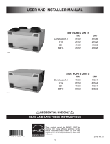
1.1 AIR DISTRIBUTION (NORMAL OPERATION)
VF0079
NOTE: The dimensions, performance charts, defrost cycle tables and specifi cations are listed on the specifi cation sheets
of the unit.
Visit our website at www.venmar.ca.
2. INSTALLATION
The wearing of safety glasses and gloves is recommended when installing, maintaining or cleaning the unit to
reduce the risk of injury that could be caused by the presence of thin metal and/or high moving parts.
WARNING
!
Stale air
from
building
Fresh air
from
outdoors
Fresh air to
building
Stale air
to
outdoors
Consumer Information
A. To ensure quiet operation of the H/ERV, each product model must be installed using sound attenuation techniques
appropriate for the installation.
B. The way your heat/energy-recovery ventilator is installed can make a signifi cant difference to the electrical energy you
use. To minimize the electricity use of the heat/energy-recovery ventilator, a stand-alone fully ducted installation is re-
commended. If you choose to connect the H/ERV to the ducting of your furnace air handler for room-to-room ventilation,
an electrically effi cient furnace that has a variable speed blower motor will minimize your electrical energy consumption
and operating cost.
Make sure that no piece of mineral wool will enter in the unit during installation. Otherwise, this could reduce
airfl ow and generate vibrations and noise in the unit.
CAUTION
2.1 INSPECT THE CONTENT OF THE BOX
NOTE: Before proceeding to the installation, check the content of the box. If items are missing or damaged, contact the
manufacturer. Remove all packaging material from the unit.
• Inspect the exterior of the unit for shipping damage. Ensure that there is no damage to the door, door latches, ports,
power cord, etc.
• Unlatch, open (A) and remove (B) the unit door.
VD0524
A
A
B

5
2.3 LOCATING AND MOUNTING THE UNIT
Choose an appropriate location for the unit:
• Within an area of the house where the ambient temperature is kept between 10°C (50°F) and 40°C (104°F);
• Away from living areas (dining room, living room, bedroom), if possible;
• So as to provide easy access to the interior cabinet for maintenance, and to the control panel on the side of the unit;
• Close to an exterior wall, so as to limit the length of the insulated fl exible ducts to and from the unit;
• HRV units only: close to a drain. If no drain is close by, use a pail to collect run-off;
• Away from hot chimneys, electrical panel and other fi re hazards;
• Within 6 feet of a power source (standard outlet).
• Inspect the inside of the unit for damage. Ensure that
blower assembly, heat or energy recovery core, core
fi lters, insulation, dampers, etc. are all intact, then
reinstall the door.
VD0525
2.2 INSTALLATION KITS, TOOLS AND MATERIAL
The installation kit needed to perform most installations is IKSV1000 for Venmar units. Following are the tools and
material needed:
• Measuring tape
• Phillips no. 2 or Robertson no. 2 screwdriver
• Small fl at blade screwdriver (for wall control connection)
• Wire stripper (for wall control connection)
• Hammer and fl at blade screwdriver (for plenum connection installation only, to make holes in existing metal duct)
• Scissors or utility knife (to cut duct tape)
• Duct tape
• Tin snips or metal shear (for plenum connection installation only, to cut ductwork)
• Aluminum duct tape (for plenum connection installation only)
• Jig saw
• Caulking gun and caulking

6
Suspended to the joists or trusts:
• Slightly bend the brackets on the unit to insert the provided chains.
• Hang the unit to the joists using the provided chains. Springs are not required.
• Always make sure that the unit is no more than 1/4" off level.
OR
Wall mounted:
• Choose the appropriate location(s) for the mounting brackets
(see illustration below) according to stud(s) position.
• Insert the provided brackets under the unit frame (see illustration
hereafter).
• Fix the bracket using the screw no. 8 x 3/8".
• Using the 4 no. 8 x 1½" screws provided, secure the unit to the wall
making sure that the 4 screws engage into a stud.
• Always make sure that the unit is no more than 1/4" off level.
2.3 LOCATING AND MOUNTING THE UNIT (CONT’D)
VD0486
VD0528
INSTALLATION WITH 2 BRACKETS INSTALLATION WITH 4 BRACKETS
Ports not shown to ease comprehension

7
VH0165
A
B
STALE AIR FROM BUILDING:
• Install registers in areas where contaminants and humidity are
produced: kitchen, bathrooms, laundry room, etc.
• Install registers on an interior wall, 6 to 12 inches away from
the ceiling OR in the ceiling.
• Install the kitchen register at least 4 feet away from the range.
• Bathroom fans and range hoods can be used to better exhaust
stale air.
• Homes with more than one level require at least one exhaust
register at the highest level.
FRESH AIR TO BUILDING:
• Install registers in bedrooms, dining room, living room and
basement.
• Install registers in the ceiling OR high on the walls with the
airfl ow directed towards the ceiling.
• If a register must be installed in the fl oor, direct the airfl ow up
the wall.
2.4.1 FULLY DUCTED SYSTEM (PRIMARILY FOR HOMES WITH RADIANT HOT WATER OR ELECTRIC BASEBOARD HEATING)
2.4 INSTALLING THE DUCTWORK AND THE REGISTERS
Never install a stale air exhaust register in a room where there is a combustion device, such as a furnace, gas
water heater, fi replace or any appliance or equipment that can generate gaseous contaminants, or pollutants.
The negative pressure this could create in the room may impair proper evacuation of the gas or pollutants,
which may have severe health consequences.
WARNING
!
STALE AIR FROM BUILDING:
Same as for Fully Ducted System, described on point 2.4.1.
FRESH AIR TO BUILDING:
• Connect the fresh air distribution duct of the unit to the central
forced-air system return duct at least 10 feet away from the
central forced-air system (A+B)*.
* This 10-ft. distance applies only in areas where the outside
temperature falls below the freezing point 0°C (32°F).
NOTE: It is recommended, but not essential that the central forced-
air system blower runs when the unit is in operation.
2.4.2 EXHAUST DUCTED SYSTEM (DUCTING TO A FORCED AIR SYSTEM)
Duct connection to the central forced-air system can be regulated by some codes and standards. It is your
responsibility to consider and comply with your local requirements to avoid any non-compliance.
WARNING
!
NOTE: A home with multiple forced air systems should have one
unit on each system.
Stale air from
bathroom
Fresh air to
building
Stale air to
outdoors
Fresh air from
outdoors
If ducts have to go through an unconditioned space (e.g.: attic), always use insulated ducts to prevent condensation
formation inside and outside ducts, which could cause material damage and/or mold growth. Moreover, if
fresh air to building duct and/or stale air from building duct goes/go through an unconditioned space, the unit
must be set to operate continuously in cold conditions (below 10°C/50°F). Continuous air movement inside
ducts will prevent condensation formation. The unit can be stopped temporarily for maintenance and/or repair
purposes in such conditions.
CAUTION
A+B= MIN 10’
In every case, bathroom fans and a range hood could be used to exhaust stale air. However, please note that an optional
bathroom installation kit (no. IKBV1000 for Venmar units) is available for houses where there is no bathroom fan.
Unit with side ports shown for graphical representation
Do not connect the unit to any forced air system distribution duct.
CAUTION

8
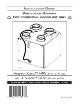
2.4.3 SIMPLIFIED INSTALLATION (DUCTING TO A FORCED AIR SYSTEM)
The central forced-air system blower must always be in operation when the unit is running since fresh air
evacuation and distribution come from the same section. The central forced-air system blower must operate
to avoid fresh air to be directly drawn by the evacuation, which would reduce signifi cantly fresh air supply
to the building.
CAUTION
Duct connection to the central forced-air system can be regulated by some codes and standards. It is your
responsibility to consider and comply with your local requirements to avoid any non-compliance.
WARNING
!
Fresh air and exhaust air fl ow through the central forced-air
system ducts, which simplifi es the installation.
The use of bathroom fans and a range hood is suggested to
exhaust stale air.
STALE AIR FROM BUILDING:
Connect the stale air intake port of the unit to the central forced-
air system return duct at least 3 feet ahead of the fresh air
distribution from the unit.
FRESH AIR TO BUILDING:
Connect the fresh air distribution duct of the unit to the central
forced-air system return duct at least 10 feet away from the
central forced-air system (A+B)*.
* This 10-ft. distance applies only in areas where the outside
temperature falls below the freezing point 0°C (32°F).
VH0167
C
B
A
A+B= MIN 10’
C=3’
Fresh air to
building
Stale air from
building
Stale air to
outdoors
Fresh air from
outdoors
NOTE: A home with multiple forced air systems should have one
unit on each system.
Do not connect the unit to any forced air system supply duct.
CAUTION

9
2.5 CONNECTING THE DRAIN (HRV ONLY)
Install the drain hose included and run it to a drain or a pail. This unit may generate a large amount of water
in cooler weather. It is necessary to install the drain hose properly to prevent water damage and/or material
damage.
CAUTION
• Cut the appropriate lengths of drain tubing (see illustration at right).
• Connect the tubings to the provided adaptor.
• Make a water trap loop in the tube to prevent the unit from drawing
unpleasant odors from the drain source.
• Add water in the loop to prevent noise or hiss.
• Make sure there is a distance of at least 2" between the unit and the
tubing loop (see illustration at right).
• Using the tie wraps provided, attach the tubing as illustrated below.
• Run the tube to the fl oor drain or to an alternate drain pipe or pail.
• IMPORTANT: If using a pail to collect water, place the tube end
approximately 1" inside the pail in order to prevent water from being
drawn back up into the unit.
2.6 INSTALLING DUAL EXTERIOR HOOD USING TANDEM® TRANSITION KIT (OPTIONAL)
For units set at 110 CFM or less, a Tandem transition kit can be used instead of 2 exterior
hoods; but take into account this device will generate approximately an additional 0.2 in w.g.
static pressure depending on the installation.
The minimum joist opening needed to install the Tandem® transition is 9¾". The maximum
height of the Tandem transition is 8¾".
To connect the insulated fl exible ducts to the Tandem transition (Exhaust air to outdoors
and Fresh air from outdoors), follow the instructions included with the Tandem transition kit
(part no.14690), included in IKSV1000 kit. VR0003
Select TANDEM speed setting to use this transition kit with your unit. See section 4 for more details.
CAUTION
t2"(51 mm)
r1"(25 mm)
5 1/4" (133 mm)
9 3/4" (248 mm) T
VO0296
Tie Wrap
Tie Wrap

10
TRANSITIONING TO 6-IN. DUCTS
If using 6-in. ducts, install 5-in. to 6-in. transitions on the ports, and secure using duct tape only. If rigid ducting is used,
install a 12-in. section of fl exible duct between the transition and the rigid ducting (see above).
RIGID DUCTS
To prevent potential water leakage in cold side rigid ducting insulation, seal all rigid ducting joints with duct tape.
To avoid transmission of vibrations, always use a 12-inch section of fl exible duct to connect rigid ducts to the unit. To
connect insulated rigid ducts to the unit (cold side) using insulated fl exible ducts, follow instructions in section 2.7. To
connect regular rigid ducts (warm side) to the unit using non-insulated fl exible ducts, use a tie wrap.
2.8 CONNECTING THE DUCTS TO THE UNIT
INSULATED FLEXIBLE DUCTS
Use the following procedure to connect the insulated fl exible ducts to the ports of the unit (exhaust to outside and fresh
air from outside).
1. Expose the fl exible duct by pulling back the insulation, and place it over the inner port ring.
2. Attach the fl exible duct to the port using a tie wrap.
3. Seal the joint using duct tape.
4. Pull the insulation and vapor barrier over the joint, tuck them between the inner and outer rings of the double collar and
fasten them in place using duct tape.
V
J0157
• If ducts have to go through an unconditioned space (e.g.: attic), always use insulated ducts to prevent
condensation formation inside and outside ducts, which could cause material damage and/or mold growth.
• Do not use screws to connect the ducts or transitions to the ports so as not to interfere with ports
inner dampers operation. A non-functioning damper could freeze the unit, which could cause damages.
CAUTION
The vapor barrier should remain intact and free of cracks or openings. An opening could produce condensation
inside or outside duct, which could cause material damage and/or mold growth in the long run.
CAUTION
2.7 INSTALLING THE EXTERIOR HOODS
To avoid cross-contamination:
• Keep at least 6 feet between both hoods OR use approved combined
hoods model 14690.
• Install hood(s) at least at 18 inches away from the ground OR depth of
expected snow accumulation, whichever is greater.
Refer to illustration above for proper connection
method of the insulated ducts to the hoods. An
“Anti-Gust Intake Hood” should be installed in
regions where a lot of snow is expected to fall.
VD0028
EXHAUST
HOOD
INTAKE
HOOD
18”
18”
6’
6’
18”
OPTIONAL
DUCT LOCATION
TAPE AND DUCT TIE
CAULKING
Make sure intake hood is at least 6 feet (1.8 m) away from any
of the following:
• Dryer exhaust, high effi ciency central forced-air system vent,
central vacuum vent
• Gas meter exhaust, gas barbecue-grill
• Any exhaust from a combustion source
• Garbage bin and any other source of contamination.
Ignoring these recommendations could signifi cantly degrade the
quality of the incoming air which, in some cases, could result in
health consequences.
In the event of a confl ict between our conditions and local
requirements, the latter will have priority.
WARNING
!
CAULKING

11
2.8.1 DUCTS CONNECTION
VD0529
CORRECT INSTALLATION
VD0530
INCORRECT INSTALLATION
IMPORTANT: Make sure to connect ducting as illustrated below to achieve the factory preset airfl ows. Correct
installation will also allow proper drainage of water that may accumulate in ducting.
Ducting must not be too crushed. Otherwise, factory preset airfl ows accuracy will be affected.
CAUTION
R = 3" minimum
NOTE: Route ducts as straight as possible, minimize the number of elbows and design and install ducts in accordance with
HRAI best practices.

12
3. CONTROLS
3.1 AUTOMATIC MAIN WALL CONTROL INSTALLATION
Cut a 27/8” x 1¾” hole in a wall, at a convenient location for the control. Route the
included 40 ft cable (type 22/4) for the control from the unit to this hole. See figure at
right.
Temporarily place the control over the hole and mark both mounting screw hole
positions.
Remove the control, drill both screw holes (3/16” Ø) in wall and insert the included wall
anchors.
Ø 3/16", typ.
VC0213A
Unplug the ventilation unit.
VC0214
Mount the control to the wall using included screws.
Gnd
D+
12V
D-
Strip the end of the cable to access the 4 wires (about 3”). Strip the end of each wire (about 1/4”). Use screws
to fi x the wires to the control terminals, regardless of the wire color or following the note below. Note
which wire color has been chosen for each terminal. Pull slightly on each wire to make sure they are firmly
connected.
NOTE: If the control is to be installed in an electric box, go to step .
Electrical wiring must be done by qualifi ed personnel in accordance with all applicable codes and standards.
Before connecting wires or making any connections, unplug the unit or switch power off at service panel and
lock service disconnecting means to prevent power from being switched on accidentally. Failure to cut power
could result in electrical shock or damage to the wall control or electronic module inside the unit. Always wear
safety glasses and gloves while performing these instructions.
Never install more than one main wall control per unit. Make sure that the wires do not short-circuit between
themselves or by touching any other components on the wall control. Avoid poor wiring connections. To
reduce the risk of electrical interference (noise), do not run wall control wiring next to control contactors or
near light dimming circuits, electrical motors, dwelling/building power or lighting wiring or power distribution
panel.
CAUTION
WARNING
!
If ducts have to go through an unconditioned space (e.g.: attic), always use insulated ducts to prevent condensation
formation inside and outside ducts, which could cause material damage and/or mold growth. Moreover, if
fresh air to building duct and/or stale air from building duct goes/go through an unconditioned space, the unit
must be set to operate continuously in cold conditions (below 10°C/50°F). Continuous air movement inside
ducts will prevent condensation formation. The unit can be stopped temporarily for maintenance and/or repair
purposes in such conditions (refer to section 2.4 for more details).
CAUTION
NOTE: We suggest to use the following wire
colors for each terminal:
Red wire for the ‘‘12 V’’ terminal,
Yellow for ‘‘D-’’,
Green for ‘‘D+’’ and
Black for ‘‘Gnd’’.

13
Use the terminal connector included, by unplugging it fi rst, to perform the electrical connection for main wall control. Use
screws to fi x wires in the terminal connector. Check if all wires are fi rmly connected in their corresponding holes in the
terminal connector by slightly pulling on each wire.
Gnd
D+
12V
D-
VC0241
12V
D-
D+
Gnd
Once the wall control connections have been made, insert the terminal connector in the electrical compartment.
UNIT BOTTOM VIEW
TERMINAL CONNECTOR
3.3 ELECTRICAL CONNECTION TO 20-40-60 OPTIONAL AUXILIARY WALL CONTROL (PART NO.204060R)
Gnd
OVR
12V
LED
VC0243
Gnd
OVR
12V
LED
NOTE : The auxiliary wall control can be used with a 3-wire connection by removing the LED signals. This optional wiring
will not allow an installation with more than 1 auxiliary wall control to properly synchronize their LEDs on an event
requested from a peer. Only the auxiliary wall control having requested the timer event will have the LEDs updated
accordingly.
3.2 ELECTRICAL CONNECTION TO AUTOMATIC MAIN WALL CONTROL (PART NO.41404)
NOTE: To avoid miswiring, refer to the notes taken at step of section 3.1 to match the wire color with the right
terminal.
Plug the ventilation unit and test the wall control.
NOTE : For more information about the installation and operation of the auxiliary wall control, refer to the included
Installation and User Guide, which is also available at www.venmar.ca.
NOTE : The auxiliary wall control is connected to the same connector as the main wall control.

14
3.4 AUTOMATIC MAIN WALL CONTROL OPERATION
The main button works following this sequence:
• Click 1 = RECIRC
• Click 2 = INT
• Click 3 = MIN
• Click 4 = MED
• Click 5 = MAX
• Click 6 = OFF
• and so on
The indicator lights up as per the selected mode.
RECIRC: Recirculate air inside the house at MAX speed.
INT: Within a one hour period, the system will operate in MIN speed for 20 minutes
and in OFF or RECIRC mode for 40 minutes depending on the selected setting
(refer to section 4.3).
MIN/MED/MAX: Continuous exchange ventilation at selected speed.
• Press the TURBO button to get 4 hours of ventilation in MAX speed. The TURBO
indicator will light up. Once the 4-hour period is done, the system will operate
according to the previous setting.
• Press the AUTO button to let the system operate according to outdoor temperature.
The AUTO indicator will light up. The AUTO indicator will light up and the system
will operate as follows:
• Less than -25°C = 10 min/hr
• -25°C to -7°C = 20 min/hr
• -7°C to 10°C = 40 min/hr
• 10°C to 25°C = MIN speed
• 25°C to 28°C = 30 min/hr
• 28°C to 33°C = 20 min/hr
• Above 33°C = 10 min/hr
• If the maintenance indicator is lit, it means that the filter needs to be cleaned or
replaced. Once the filter is cleaned or replaced, press the AUTO button for five
seconds to reset the maintenance indicator. If the maintenance indicator flashes,
the LCD screen on the unit will give the error code. Refer to the Troubleshooting
section for more information.
• At unit first boot, AUTO and TURBO indicators blink alternately for about 1 minute.
If indicators continue blinking after this period, it means that the communication
cannot be established with the ventilation unit. Make sure wires are correctly
connected to the wall control and unit terminals (refer to sections 3.1 and 3.2).

15
4. NAVIGATION ON LCD SCREEN
+
-
OK
VD0492
OK button To confi rm a selection.
+ button To increase a value.
To scroll up in a selection.
- button To decrease a value.
To scroll down in a selection.
VQ0212
Indicates current
mode
VQ0210 VQ0201
+
-
PRESS ON + BUTTON OR - BUTTON TO MODIFY OPTIONS CONFIGURATION.
PRESS ON OK BUTTON DU-
RING 4 SECONDS TO MODIFY
OPTIONS CONFIGURATION.
VQ0197
VQ0200
FOR EACH
OPTION
CONFIGURATION,
USE + BUTTON
TO SCROLL UP
IN OPTIONS
AVAILABLE OR
- BUTTON TO
SCROLL DOWN
IN OPTIONS
AVAILABLE.
ONCE OPTION
SELECTION IS
DONE, PRESS
OK BUTTON
TO CONFIRM
SELECTION. THE
NEXT OPTION
CONFIGURATION
WILL THEN
DISPLAY.
VQ0221
USE MAIN WALL CONTROL
TO CHANGE UNIT OPERATING
MODE.
MODE

16
4.3 SETTINGS MODIFICATION
• Go to CFG OPT using (+/-) then press on the OK button for 4 seconds.
4.2 UNIT FIRST BOOT
PREPARATION
Follow these steps to ensure a successful boot:
• Seal all the ductwork with tape. Close all windows and doors.
• Turn off all exhaust devices such as range hood, dryer and bathroom fans.
• If the installation is in any way connected to a ductwork of a central forced-air system, make sure that the central forced-air
system blower is ON. If not, leave central forced-air system blower OFF.
BOOT UP PROCEDURE
• Plug the unit and wait for the STB mode to display on the LCD screen. If unit is colder than ambient temperature, it is normal to
experience a 60 s longer boot-up since motors have to preheat.
4.1 DISPLAY ON LCD SCREEN
DISPLAY DEFINITION
STB Standby mode
MED MED speed
INT Intermittent mode
REC Recirculation mode
(Min, Med or Max speed)
AUT AUTO mode
OVR 20 Override 20 min
Options Confi gurations available
DEF (Defrost) DIS* (Discretion - defrost without speed variation for more comfort),
PLU (Plus - extended defrost for colder areas)
INT (Intermittent)
STB (Standby - 20 min in MIN speed and 40 min in standby mode), REC* (Recirculation - 20 min
in MIN speed and 40 min in recirculation mode)
NOTE: Following ducting installation confi guration and temperature conditions, it may be
necessary for the unit to operate continuously. Refer to section 2.4 for more details.
SPD (Speed)
HRV110 DFT* (Default - MIN/MED/MAX = 50/81/112 CFM)
HRV110 TDM (Tandem - MIN/MED/MAX = 50/64/90 CFM)
ERV130 DFT* (Default - MIN/MED/MAX = 64/96/131 CFM)
ERV130 TDM (Tandem - MIN/MED/MAX = 50/70/105 CFM)
If needed, reset settings to restart the boot up procedure.
PROCEDURE TO RESET SETTINGS
Press on the OK and (-) buttons simultaneously for 4 seconds. Use (+/-) to select Yes or No and OK to confi rm.
Then perform the boot up procedure.
NOTE: If no selection is confi rmed within 10 minutes, the unit will exit the menu without saving any changes.
* Factory setting
4.4 FACTORY SETTINGS RESET
VQ0203
Indicates
fresh airfl ow
Indicates
stale airfl ow
4.5 MANUAL MODE
This mode is meant for qualifi ed personnel only in case of troubleshooting. Operating the unit continuously
in manual mode can reduce comfort and increase risk of frost following improper airfl ows confi guration.
Damage to the unit and/or property damage could result. It is highly recommended to use manual mode on
a temporary basis only when needed and to reset the unit factory settings once the use of this mode is over
(refer to section 4.4).
CAUTION
Press simultaneously (+/-) buttons for 4 seconds.
Use (+/-) to adjust fresh air airfl ow and OK to confi rm.
Use (+/-) to adjust stale air airfl ow and OK to confi rm.
If needed, press OK to readjust airfl ows.
Press + or - button, change mode on main wall control or use optional auxiliary wall control to
leave manual mode.
When leaving manual mode, settings are lost.
DISPLAY DEFINITION
OVR 40 Override 40 min
OVR 60 Override 60 min
TUR Turbo mode
DEF Defrost mode
EXX or WXX
(XX referring to error or warning
number)
Refer to section 7 for each error/warning
explanation

17
5. USING THIS UNIT
Once your installation is completed, enjoy a better indoor air quality. This balanced ventilation unit is designed to bring
fresh fi ltered air inside while eliminating stale air and airborne pollutants. Venmar fresh air systems care about your health
by improving your indoor air quality and home comfort.
The unit is also energy effi cient. It recovers heat or energy depending on the model to improve comfort and energy
effi ciency during the heating and cooling periods.
5.1 YOUR VENTILATION SYSTEM
5.2 CONTROLS
All units are equipped with an integrated control, located in front of the electrical compartment. A wall control is also
included with the unit and must be installed for unit operation. An optional auxiliary wall control for the bathroom can be
installed.
UNIT OPERATION
Use your Automatic main wall control to select the appropriate mode to suit your needs and desired comfort.
Select:
- AUTOMATIC mode to let the system adjust the ventilation mode in an autonomous way by evaluating outdoor
temperature;
- MIN, MED or MAX speed for a continuous fresh air intake;
- INTERMITTENT mode for 20 minutes in MIN speed continuous fresh air intake and 40 minutes in STANDBY or RECIRCU-
LATION;
- RECIRCULATION mode to recirculate the air inside without any fresh air coming in from outside.
- TURBO mode for a 4-hour countdown timer at MAX speed exchange ventilation for high activity event.
1. See section 3.4 for the main wall control operation.
2. See section 4 for integrated control operation.
3. See corresponding installation and user guide on www.venmar.ca for the auxiliary wall control operation.
NOTE: If an optional auxiliary wall control is used, it overrides the main wall control.
6. SERVICE PARTS
DESCRIPTION PART NUMBER
MERV8 fi lters kit SV66133 1 1
Optional HEPA membrane fi lter V25000 1 1
HRV110
ERV130
All parts listed in the following table are available where you bought your unit or in an authorized service center.
NOTE: Please note that parts not listed are not available; those parts require assembly knowledge that only manufacturer
can guarantee.
REPLACEMENT PARTS AND REPAIRS
In order to ensure your ventilation unit remains in good working condition, you must use the
manufacturer’s genuine replacement parts only. The manufacturer’s genuine replacement parts are
specially designed for each unit and are manufactured to comply with all the applicable certifi cation
standards and maintain a high standard of safety. Any third party replacement part used may cause
serious damage and drastically reduce the performance level of your unit, which will result in premature
failing. The manufacturer recommends to contact a certifi ed service depot for all replacement parts and
repairs.

18
7. INSTALLER’S TROUBLESHOOTING
The wearing of safety glasses and gloves is recommended since a few diagnosis procedures may require the
unit to be in operation while proceeding. Be careful with moving and live parts to prevent any risk of injury.
WARNING
!
ERROR DESCRIPTION SOLUTION
E01 Supply damper range STEP 1: Unplug unit, inspect the damper system, remove any undesirable
obstacle or dirt (fi lters and core may have to be removed to access the
damper system). Plug unit.
If STEP 1 did not fi x the problem, contact customer service.
E02 Supply damper timeout
E03 Supply damper
E05 Exhaust damper range
E06 Exhaust damper timeout
E07 Exhaust damper
E09 Recirculation damper range
E10 Recirculation damper timeout
E11 Recirculation damper
E22 Supply (fresh) airfl ow STEP 1: Unplug the unit. Perform a visual inspection of the supply damper
system. Clean fi lters, distribution registers and outside supply hood. Inspect
ducting to ensure it is not squeezed or bent. Plug the unit.
If STEP 1 did not fi x the problem, perform STEP 2: Unplug unit and remove
ducting of the supply path. Replug the unit. On the wall control, select MAX
to check if the error code disappeared. If so, review the ducting path.
If STEP 2 did not fi x the problem, contact customer service.
E23 Supply motor (drive over current) STEP 1: Unplug/plug unit.
If STEP 1 did not fi x the problem, perform STEP 2: Unplug the unit. Remove
core and clear the ventilation wheel from any dirt or obstacles. Place back
the core, close the door and plug the unit.
If STEP 2 did not fi x the problem, contact customer service.
E27 Supply motor (drive foc duration)
E28 Supply motor (drive speed feedback)
E29 Supply motor (startup)
E24 Supply motor (drive over voltage) STEP 1: Unplug/plug unit. Under and over voltage may be detected with
severe in-house power supply fl uctuation and stop the motor for protection.
If STEP 1 did not fi x the problem, contact customer service.
E25 Supply motor (drive under voltage)
E26 Supply motor (drive over temp) STEP 1: Validate if the air exchanger is exposed to ambient temperatures
within the operating limits (see section 2.3)
If STEP 1 did not fi x the problem, contact customer service.
E32 Exhaust (stale) airfl ow STEP 1: Unplug the unit. Perform a visual inspection of the exhaust damper
system. Clean fi lters, distribution registers and outside supply hood. Inspect
ducting to ensure it is not squeezed or bent. Plug the unit.
If STEP 1 did not fi x the problem, perform STEP 2: Unplug unit and remove
ducting of the supply path. Replug the unit. On the wall control, select MAX
to check if the error code disappeared. If so, review the ducting path.
If STEP 2 did not fi x the problem, contact customer service.
E33 Exhaust motor (drive over current) STEP 1: Unplug/plug unit.
If STEP 1 did not fi x the problem, perform STEP 2: Unplug the unit. Remove
core and clear the ventilation wheel from any dirt or obstacles. Place back
the core, close the door and plug the unit.
If STEP 2 did not fi x the problem, contact customer service.
E37 Exhaust motor (drive foc duration)
E38 Exhaust motor (drive speed
feedback)
E39 Exhaust motor (startup)
E34 Exhaust motor (drive over voltage) STEP 1: Unplug/plug unit. Under and over voltage may be detected with
severe in-house power supply fl uctuation and stop the motor for protection.
If STEP 1 did not fi x the problem, contact customer service.
E35 Exhaust motor (drive under voltage)
E36 Exhaust motor (drive over temp) STEP 1: Validate if the air exchanger is exposed to ambiant temperatures
within the operating limits (see section 2.3)
If STEP 1 did not fi x the problem, contact customer service.
When the unit detects an error, the corresponding error code displays on the LCD screen.

19
ERROR DESCRIPTION SOLUTION
E40 Outside air thermistor STEP 1: Contact customer service.
E42 PCBA thermistor fault
E43 PCBA temperature over limit STEP 1: Validate if the air exchanger is exposed to ambiant temperatures
within the operating limits (see section 2.3)
If STEP 1 did not fi x the problem, contact customer service.
E50 Wall control communication lost STEP 1: Unplug unit, inspect wall control wires, plug unit.
If STEP 1 did not fi x the problem, perform STEP 2: Remove wall control from
the wall installation and test with a short cable. If it works, bring a new cable
to the wall installation location.
If STEP 2 did not fi x the problem, perform STEP 3: Test the air exchanger with
a spare wall control. If it works, replace the wall control.
If STEP 3 did not fi x the problem, contact customer service.
7. INSTALLER’S TROUBLESHOOTING (CONT’D)
WARNING DESCRIPTION SOLUTION
W61 Protection mode
electronics
overheating
The unit is currently in protection mode. The power transmitted to the motor is deliberately
reduced to decrease electronics temperature. The unit will exit this mode by itself once
conditions are back to normal. It is normal to observe reduction in airfl ows during this period.
This condition should appear only when the unit is set in high speed and located in a warmer
environment, for example over 30°C (86°F). If not, contact customer service.
Make sure that no piece of mineral wool will enter in the unit during installation. Otherwise, this could reduce
airfl ow and generate vibrations and noise in the unit.
CAUTION

20
8. MAINTENANCE
High voltage risk. During maintenance or repairs, always stop the unit then unplug it to prevent any risk of
electric shock. The wearing of safety glasses and gloves is recommended when handling unit components to
prevent any risk of injury that could be caused by the presence of thin metal.
1. Disconnect power cord.
2. The door of this unit is hinged and maintained closed by 2 latches. Open them and set aside.
3. Clean the inside of the door with a damp cloth.
4. Clean fi lters:
• Remove fi lters.
• Vacuum to remove most of the dust.
• Wash with a mixture of warm water and mild soap. You may add bleach if you wish to
disinfect (one tablespoon per gallon). Rinse thoroughly. Shake fi lters to remove excess
water and let dry.
Note: The optional HEPA membrane fi lter is a disposable fi lter. It should be replaced when it is
too dirty. Vacuum the HEPA membrane fi lter quarterly using the dusting brush attachment
to extend its service life.
5. Remove the core.
6. Clean the condensing tray with a damp cloth.
7. Check the exterior air intake hood:
• Make sure there are no leaves, twigs, ice or snow that could be drawn into the vent.
• Clean if necessary.
8. Rotate the blower wheels by hand. If one of the wheels does not rotate easily, contact customer service.
9. Reassemble the components. Pay special attention to the fi lters by making sure that they are engaged in their slots.
10. Close the unit door and reconnect power supply.
11. Reset fi lters, if required. Press on the INT/AUTO wall control button for 5 seconds to reset the fi lters.
CAUTION
A blocked air vent or fi lter, even partially, could cause the unit to malfunction. The comfort provided by the
unit could be reduced and the risk of unit frost could increase. This could cause unit breakdown and/or damage
to property.
V
D0493
8.1 QUARTERLY
WARNING
!
VD0494
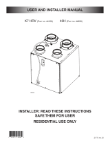
MERV8 FILTER INCLUDED
OPTIONAL HEPA MEMBRANE FILTER (NO. V25000) (EXHAUST FILTER NOT INCLUDED)
EXHAUST FILTER INCLUDED
NOTE: The optional HEPA membrane fi lter replaces the MERV8 fi lter.
Remove the HEPA membrane fi lter from its
packaging.
Write the installation date on the new fi lter
frame for future reference.
Pull the core 3" to 4" out.
Bend the two HEPA membrane fi lter fl aps to
form a 45-degree angle, as illustrated below.
Install the HEPA membrane fi lter over the core
as illustrated hereafter.
Push the core and the HEPA membrane fi lter to
the bottom of the unit.
45˚
45˚
CAUTION
Be careful not to damage the HEPA membrane fi lter if using
sharp tool to remove it from its packaging.
/