Page is loading ...

INSTALLATION GUIDE
BROAN MODELS HRVH100SE AND ERVH100SE
VB0189
These products earned the ENERGY STAR
®
by meeting strict energy efficiency guidelines set by Natural Resources
Canada and the US EPA. They meet ENERGY STAR requirements only when used in Canada.
RESIDENTIAL INDOOR USE ONLY
! !
READ AND SAVE THESE INSTRUCTIONS
99528512A
Broan-NuTone LLC; Hartford, Wisconsin www.broan.com 800-558-1711
REGISTER YOUR PRODUCT ONLINE AT: www.broan.com/register
For additional information - visit www.broan.com

2
Please take note that this manual uses the following symbols to emphasize particular information:
Identies an instruction which, if not followed, might cause serious personal injuries including possibility of death.
Identies an instruction which, if not followed, may severely damage the unit and/or its components.
NOTE: Indicates supplementary information needed to fully complete an instruction.
WARNING
!
CAUTION
ABOUT THIS GUIDE
ABOUT THESE UNITS
LIMITATION
For residential (domestic) installation only. Installation work and electrical wiring must be done by a qualied person(s) in accordance with
all applicable codes and standards, including re-rated construction codes and standards.
WARNING
!
TO REDUCE THE RISK OF FIRE, ELECTRIC SHOCK, OR INJURY TO PERSON(S) OBSERVE THE FOLLOWING:
1. Use this unit only in the manner intended by the manufacturer. If you have questions, contact the manufacturer at the address or
telephone number listed in the warranty.
2. We recommend that your unit be inspected by a specialized technician once a year.
3. Before servicing or cleaning the unit, disconnect power cord from electrical outlet.
4. This unit is not designed to provide combustion and/or dilution air for fuel-burning appliances.
5. When cutting or drilling into wall or ceiling, do not damage electrical wiring and other hidden utilities.
6. Do not use the units with any solid-state speed control device other than the corresponding ones listed below:
7. This unit must be grounded. The power supply cord has a 3-prong grounding plug for your personal safety. It must be plugged in to a
mating 3-prong grounding receptacle, grounded in accordance with the national electrical code and local codes and ordinances.
Do not remove the ground prong. Do not use an extension cord.
8. Do not inst
all in a cooking area or connect directly to any appliances.
9. Do not use to exhaust hazardous or explosive materials and vapors.
10. When performing installation, servicing or cleaning the unit, it is recommended to wear safety glasses and gloves.
11. Due to the weight of the unit, two installers are recommended to perform installation.
12. When applicable local regulations comprise more restrictiv e installation and/or certication r equirements, the aforementioned requirements
prevail on those of this document and the installer agrees to conform to these at his own expenses.
UNIT MAIN CONTROL AUXILIARY CONTROL
HRVH100SE AND W02BV01404SE001HVRE
CAUTION
1. To avoid prematurate clogged lters, turn OFF the unit during construction or renovation.
2. Please read specication label on product for further information and requirements.
3. Be sure to duct air outside – Do not intake/exhaust air into spaces within walls or ceiling or into attics, crawl spaces, or garage.
4. Intended for residential installation only in accordance with the requirements of NFPA 90B.
5. Do not run any air ducts directly above or closer than 2 ft (0.61 m) to any furnace or its supply plenum, boiler, or other heat producing
appliance. If a duct has to be connected to the furnace return plenum, it must be connected not closer than 9’ 10” (3 m) from this plenum
connection to the furnace.
6. The ductwork is intended to be installed in compliance with all applicable codes.
7. When leaving the house for a long period of time (more than two weeks), a responsible person should regularly check if the unit
operates adequately.
8. If the ductwork passes through
an unconditioned space (e.g.: attic), the unit must operate continuously except when performing
maintenance and/or repair. Also, the ambient temperature of the house should never drop below 65°F (18°C).

TABLE OF CONTENTS
3
1. D IMENSIONS . . . . . . . . . . . . . . . . . . . . . . . . . . . . . . . . . . . . . . . . . . . . . . . . . . 3
2. T
YPICAL INSTALLATIONS. . . . . . . . . . . . . . . . . . . . . . . . . . . . . . . . . . . . . . . . . . . . . . 4
2.1 FULLY DUCTED SYSTEM . . . . . . . . . . . . . . . . . . . . . . . . . . . . . . . . . . . . . . . . . . . . . . . . . 4
2.2 CENTRAL DRAW POINT . . . . . . . . . . . . . . . . . . . . . . . . . . . . . . . . . . . . . . . . . . . . . . . . . 4
2.3 SIMPLIFIED INSTALLATION . . . . . . . . . . . . . . . . . . . . . . . . . . . . . . . . . . . . . . . . . . . . . . . . . 4
3. INSTALLATION . . . . . . . . . . . . . . . . . . . . . . . . . . . . . . . . . . . . . . . . . . . . . . . . 5-11
3.1 INSPECT THE CONTENT OF THE BOX . . . . . . . . . . . . . . . . . . . . . . . . . . . . . . . . . . . . . . . . . . . . 5
3.2 TOOLS AND MATERIAL . . . . . . . . . . . . . . . . . . . . . . . . . . . . . . . . . . . . . . . . . . . . . . . . . . 6
3.3 LOCATING THE UNIT . . . . . . . . . . . . . . . . . . . . . . . . . . . . . . . . . . . . . . . . . . . . . . . . . . . 6
3.4 PLANNING OF THE DUCTWORK . . . . . . . . . . . . . . . . . . . . . . . . . . . . . . . . . . . . . . . . . . . . . . 6
3.5 INSTALLING NON-INSULATED DUCTS AND DIFFUSERS . . . . . . . . . . . . . . . . . . . . . . . . . . . . . . . . . . . 6-8
3.5.1 FULLY DUCTED SYSTEM. . . . . . . . . . . . . . . . . . . . . . . . . . . . . . . . . . . . . . . . . . . . . . . . . . . . 6-7
3.5.2 CENTRAL DRAW POINT . . . . . . . . . . . . . . . . . . . . . . . . . . . . . . . . . . . . . . . . . . . . . . . . . . . . . 8
3.5.3 SIMPLIFIED INSTALLATION . . . . . . . . . . . . . . . . . . . . . . . . . . . . . . . . . . . . . . . . . . . . . . . . . . . . 8
3.6 INSTALLING INSULATED FLEXIBLE DUCTS . . . . . . . . . . . . . . . . . . . . . . . . . . . . . . . . . . . . . . . . 9-10
3.6.1 CONNECTION TO THE UNIT PORTS . . . . . . . . . . . . . . . . . . . . . . . . . . . . . . . . . . . . . . . . . . . . . . . . 9
3.6.2 CONNECTION TO TANDEM TRANSITION . . . . . . . . . . . . . . . . . . . . . . . . . . . . . . . . . . . . . . . . . . . . . . 9
3.6.3 LOCATING EXTERIOR PORTS . . . . . . . . . . . . . . . . . . . . . . . . . . . . . . . . . . . . . . . . . . . . . . . . . . .10
3.7 CONNECTING INSULATED DUCTS TO EXTERIOR PORTS. . . . . . . . . . . . . . . . . . . . . . . . . . . . . . . . . . . 10
3.8 INSTALLING TANDEM
®
TRANSITION KIT . . . . . . . . . . . . . . . . . . . . . . . . . . . . . . . . . . . . . . . . . . 11
3.9 CONNECTING THE DRAIN . . . . . . . . . . . . . . . . . . . . . . . . . . . . . . . . . . . . . . . . . . . . . . . . 11
4. CONTROLS . . . . . . . . . . . . . . . . . . . . . . . . . . . . . . . . . . . . . . . . . . . . . . . . . 12-14
4.1 BOOTING SEQUENCE . . . . . . . . . . . . . . . . . . . . . . . . . . . . . . . . . . . . . . . . . . . . . . . . . 12
4.2 DEFROST CYCLES . . . . . . . . . . . . . . . . . . . . . . . . . . . . . . . . . . . . . . . . . . . . . . . . . . . 12
4.3 MAIN WALL CONTROL INSTALLATION. . . . . . . . . . . . . . . . . . . . . . . . . . . . . . . . . . . . . . . . . .13-14
4.4 WALL CONTROL(S) CONNECTION TO THE UNIT . . . . . . . . . . . . . . . . . . . . . . . . . . . . . . . . . . . . . . 14
5. WIRING DIAGRAM . . . . . . . . . . . . . . . . . . . . . . . . . . . . . . . . . . . . . . . . . . . . . . . 15
6. S
ERVICE PARTS . . . . . . . . . . . . . . . . . . . . . . . . . . . . . . . . . . . . . . . . . . . . . . . . 16
7. T
ROUBLESHOOTING . . . . . . . . . . . . . . . . . . . . . . . . . . . . . . . . . . . . . . . . . . . . . 17-18
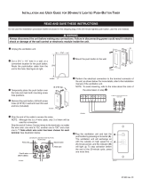
1. DIMENSIONS
11¼"
17
7
/16"
37
7
/8"
33"
11
7
/8"
VK0085A
39 /8"

4
2. TYPICAL INSTALLATIONS
Use the following illustrations as guidelines to help you decide on how the unit will be installed.
All the units should be hung from the joists.
In every case, bathroom fans and a range hood could be used to exhaust stale air. Also, for homes with more than one level, we recommend
one exhaust register at the highest level.
There are 3 installation methods: Fully Ducted System, Central Draw Point and Simplified Installation.
NOTE: An electrical outlet has to be available within 3 feet of the unit.
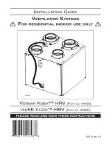
2.1 FULLY DUCTED SYSTEM (PRIMARILY FOR HOMES WITH RADIANT HOT WATER OR ELECTRIC BASEBOARD HEATING)
VH0091
Stale air coming from the register located at the highest level of the
house is exhausted to the outside. Fresh air from outside is filtered and
supplied by the register located in the lowest liveable level.
Homes with more than one level require at least one exhaust register at
the highest level.
See figure at right.
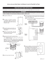
2.2 CENTRAL DRAW POINT (CONNECTION TO A FORCED AIR SYSTEM)
VH0092
Stale air coming from the register located at the highest level of the
house is exhausted to the outside. Fresh air from outside is filtered and
supplied to the return (plenum) of the forced air unit. See figure at right.
For this type of installation, it is not essential that the forced air system
blower runs when the unit is in operation, but we recommend it.
NOTE: Home with multiple forced air systems should have one unit on
each system.
2.3 SIMPLIFIED INSTALLATION (CONNECTION TO A FORCED AIR SYSTEM)
VH0093
Stale air is exhausted to the outside. Fresh air from outside is filtered and
supplied to the return (plenum) of the forced air unit.
See figure at right.
To avoid cross-contamination and achieve the highest efficiencies, the
forced air system blower must always be ON.
NOTE: Home with multiple forced air systems should have one unit on
each system.
Do not connect the unit to any forced air system supply
duct.
CAUTION
Do not connect the unit to any forced air system supply
duct.
CAUTION

5
3. INSTALLATION
• Inspect the exterior of the unit for shipping damage. Ensure that there is no damage to the door, ports, power cord, etc.
• Remove the transport tape over the heat or energy recovery core
of the unit.
• Inspect the inside of the unit for damage. Ensure that blower
assembly, heat or energy recovery core, core filters, insulation,
dampers, prefilter and HEPA filter, etc. are all intact, then reinstall
the door.
NOTE: Write the installation date on the HEPA filter frame for future
reference (see illustration at right).
TOP
DESSUS
FRONT
AVANT
Instal. date:
Date d’instal. :
__ / __ / ____
21293
FRONT
AVANT
Instal. date:
Date d’instal. :
__ / __ / ____
VD0322
NOTE: Before proceeding to the installation, check the content of the box. If items are missing or damaged, contact the
manufacturer. Remove all packaging material from the unit.
In order to prevent damages to the door hooks, do not open completely the
unit door; tilt it about 3” from the unit base and lift it up. See illustration at
right.
CAUTION
±3”
VD0303A
B
C
VD0302
A
• Using a Phillips or a Robertson screwdriver, loosen both door screws (A).
NOTE: The screws will stay attached to the door.
• Open (B) and lift out (C) the door.
3.1 INSPECT THE CONTENT OF THE BOX

6
3. INSTALLATION (CONT’D)
3.3 LOCATING THE UNIT
Choose an appropriate location for the unit.
• Within an area of the house where the ambient temperature is kept between 50°F (10°C) and 104°F (40°C).
• Away from living areas (dining room, living room, bedroom), if possible.
• So as to provide easy access to the interior of the unit, for maintenance.
• Close to an exterior wall, so as to limit the length of the insulated flexible duct to and from the unit.
• Away from hot chimneys and other fire hazards.
• Allow for a power source (standard 3-prong grounding outlet).
• FOR HRV UNITS ONLY: Close to a drain. If no drain is close by, use a pail to collect
run-off.
Hang the unit with the four hooks, chains and springs provided. See illustration at right.
VD0305
Make sure the unit is level.
CAUTION
Stale air exhaust ductwork
• Install the stale air exhaust diffuser in the main area where the contaminants are produced: kitchen, living room, etc. Position
the diffuser as far from the stairway as possible and in such a way that the air circulates in all the lived-in spaces in the house.
If desired, you can install another diffuser (sold separately).
• If a diffuser is installed in the kitchen, it must be located at least 4 feet (1.2 m) from the range.
• Install the diffuser 6 to 12 inches (152 to 305 mm) from the ceiling on an interior wall OR install it in the ceiling.
Never install a stale air exhaust diffuser in a closed room where a combustion device operates, such as a
gas furnace, a gas water heater or a fireplace.
WARNING
!
3.2 TOOLS AND MATERIAL
Following are the tools and material needed:
• Phillips no. 2 or Robertson no. 2 screwdriver
• Small flat blade screwdriver (for wall control connection)
• Wire stripper (for wall control connection)
• Hammer and flat blade screwdriver (for plenum connection installation only, to make holes in existing metal duct)
• Scissors or utility knife (to cut duct tape)
• Measuring tape
• Duct tape
• Tin snips or metal shear (for plenum connection installation only, to cut ductwork)
• Aluminum duct tape (for plenum connection installation only)
• Jig saw
• Caulking gun and caulking.
3.4 PLANNING OF THE DUCTWORK
• Keep it simple. Plan for a minimum of bends and joints.
• Keep the length of insulated ducts to a minimum.
• Do not ventilate crawl spaces or cold rooms. Do not attempt to recover the exhaust air from a dryer or a range hood. This
would cause clogging of the filters and recovery module.
• If the house has two floors or more, be sure to plan for at least one exhaust register on the highest lived-in level.
3.5 INSTALLING NON-INSULATED DUCTS AND DIFFUSERS
3.5.1 FULLY DUCTED SYSTEM (AS ILLUSTRATED IN SECTION 2.1)

7
3.5 INSTALLING NON-INSULATED DUCTS AND DIFFUSERS (CONT’D)
3.5.1 F
ULLY DUCTED SYSTEM (AS ILLUSTRATED IN SECTION 2.1) (CONT’D)
HOW TO CONNECT THE FLEXIBLE DUCTS TO THE DIFFUSERS
Once the diffusers location is determined, cut out 5¼” diameter hole.
Run one end of the flexible duct through the hole and fix it to the diffuser base (1),
using a tie wrap and duct tape. Assemble the diffuser base to the wall (or ceiling)
using its 4 no. 8 x 3/4” screws. Then, slide in the diffuser (2).
See illustration at right.
Ø 5¼”
VJ0094A
2
1
3. INSTALLATION (CONT’D)
HOW TO CONNECT THE FLEXIBLE DUCTS TO THE UNIT PORTS
Both flexible ducts attached to the diffusers must be connected to the bottom ports of
the unit. When facing the unit door, the fresh air to building port is located on left side
and the exhaust air from building port is on the right side. Refer to the identification
labels affixed beside each unit ports. Using tie wrap, attach the fresh air to building
duct to its corresponding port, then do the same for the exhaust air to building duct
and port. See illustration at right.
NOTE: Use an insulated duct if the duct will have to go through a space where it is
possible to experience extreme temperature conditions (eg: in northern area,
unheated attic in winter or uncooled attic in southern area). Also, if you plan
to stop the unit for more than 12 hours, we recommend to cover the duct with
R12 insulation.
VJ0107
Aire de salida desde el interior
RIGHT SIDE OF THE UNIT
Fresh air distribution ductwork
• Install the fresh air distribution diffuser in a large, open area in the lowest level to ensure the greatest possible air circulation.
• Keep in mind that the fresh air diffuser must be located as far as possible from the stale air diffuser. If desired, you can install
another diffuser.
• Install the diffuser either in the ceiling OR 6 to 12 inches (152 to 305 mm) from the ceiling on an interior wall. (The cooler air
will then cross the upper part of the room and mix with room air, before descending to occupant’s level.)
• If a register must be floor installed, direct the airflow up the wall.
UNIT PORTS IDENTIFICATION
Each unit port has an identification label
beside it to avoid wrong duct connections to
the unit. Always refer to these labels before
performing any duct and port connection.
VJ0106
Aire de salida hacia el exterior
Aire fresco hacia el interior
Aire fresco desde el exterior
Aire de salida desde el interior
UNIT
DOOR

8
3.5 INSTALLING NON-INSULATED DUCTS AND DIFFUSERS (CONT’D)
Fresh air distribution ductwork (return side connection)
Same as for Central Draw Point, described in step 3.5.2
3.5.3 S
IMPLIFIED INSTALLATION (AS ILLUSTRATED IN SECTION 2.3)
Stale air exhaust ductwork (return side connection)
When performing duct connections, always use approved tools and materials. Respect all corresponding
laws and safety regulations. Please refer to your local building code.
WARNING
!
• Locate the opening for stale air ductwork on the forced air unit at least 3’ (0.9 m)
from fresh air ductwork connection. Cut out a 5” Ø hole in this location, using
metal shear.
• Use a steel transition (not included, available in hardware store) to connect the
unit duct to the forced air unit return duct.
• Attach the other end of the flexible duct to the Exhaust air from building port
(see icon on the right side of the unit). Use tie wrap and duct tape to seal the
connection. See illustration at right.
The furnace blower must be running when the ventilation unit is in operation.
CAUTION
3. INSTALLATION (CONT’D)
VJ0109
3’ (0.9 M)
MINIMUM
UNIT DOOR
A + B + C = NOT LESS
THAN 9’ 10” (3 M)
Stale air exhaust ductwork
Same as for Fully Ducted System, described in step 3.5.1
3.5.2 C
ENTRAL DRAW POINT (AS ILLUSTRATED IN SECTION 2.2)
Fresh air distribution ductwork
When performing duct connections, always use approved tools and materials. Respect all corresponding
laws and safety regulations. Please refer to your local building code.
WARNING
!
• Locate the opening for fresh air ductwork on the forced air unit return duct
at a minimum linear distance of 9’ 10” (3 m) upstream (from forced air unit drop:
A+B+C). Cut out a 5” Ø hole in this location, using metal shear.
• Use a metal transition (not included, available in hardware store) to connect the
unit duct to the forced air unit return duct.
• Attach the other end of the flexible duct to the Fresh air to building port (see
icon on the left side of the unit). Use tie wrap and duct tape to seal the connection.
See illustration at right.
VJ0099
A + B + C = NOT LESS
THAN 9’ 10” (3 M)
U
NIT DOOR
METAL
TRANSITION

9
Make sure the vapor barrier on the insulated ducts does not tear during installation to avoid condensation
within the ducts.
CAUTION
3. INSTALLATION (CONT’D)
3.6 INSTALLING INSULATED FLEXIBLE DUCTS
Use the following procedure for connecting the insulated flexible ducts to the unit ports (exhaust air to outside and fresh air from
outside). Refer to identification labels beside ports before performing any duct and port connection.
For both remaining ducts, pull back the insulation to expose
the interior flexible duct.
Connect the interior flexible duct to the smaller part of the
inner ring of the port using a tie wrap.
Pull the insulation over the joint and tuck it between the
inner and outer rings of the port. Pull the vapor barrier over
the insulation and over the outer ring of the port.
Apply duct tape gently to the joint in order to make an airtight
seal. See figures at right.
3.6.1 C
ONNECTION TO THE UNIT PORTS
VJ0102
Avoid compressing the insulation pulling the tape tightly around the joint. Compressed insulation loses its
insulation properties and causes water dripping due to condensation on the exterior surface of the duct.
CAUTION

3.7 CONNECTING INSULATED DUCTS TO EXTERIOR PORTS
• For each exterior port, using a jig saw, cut a 5’’ diameter hole in the
exterior wall.
• From the outside, slide the exterior port in place and attach it to the
exterior wall, using 2 no. 8 x 1½” provided screws. Seal the outline with
silicone.
• From the inside, pull back the insulation to expose the flexible duct and,
using a tie wrap, attach it to the exterior port rigid duct. Carefully seal
with duct tape. Pull the insulation over the joint. Pull the vapor barrier
over the insulation and over the joint. Apply gently duct tape to the joint
making an airtight seal. See illustration at right.
VR0028
Choose an appropriate location for installing the exterior ports:
• There must be a minimum distance of 6’ (1.8 m) between the hoods to avoid cross-contamination
• There must be a minimum distance of 18” (457 mm) from the ground
3.6.2 L
OCATING EXTERIOR PORTS
VD0203
Make sure the fresh air intake port is located at least 6 feet (1.8 m) away (or more, as per applicable building
codes or standards) from sources of contamination such as:
• Dryer exhaust, high efficiency furnace vent, central vacuum vent
• Gas meter exhaust, gas barbecue grill
• Garbage bin
• Any exhaust from a combustion source
WARNING
!
6’
(1.8 M)
6’
(1.8 M)
STALE AIR
EXHAUST PORT
18’’
(457 MM)
18’’ (457 MM)
5’’ Ø
(127 MM)
5’’ Ø
(127 MM)
FRESH AIR
INTAKE PORT
OPTIONAL
LOCATION
3. INSTALLATION (CONT’D)
3.6 INSTALLING INSULATED FLEXIBLE DUCTS (CONT’D)
10

11
3.9 CONNECTING THE DRAIN
Cut two sections of plastic tubing, approximately
12” long, and connect each one to both inner drain
fittings located under the unit as shown.
Join these both sections to the “T” junction and
main tube as shown, to prevent the unit from
drawing unpleasant odors from the drain source.
VD0308A
± 1”
Run the tube to the floor
drain or to an alternative
drain pipe or pail.
IMPORTANT
If using a pail to collect
water, locate the tube end
approximately 1” from the
top of the pail in order to
prevent water from being
drawn back up into the unit.
VD0311A
± 12” ± 12”
TIE WRAP
A drain tubing (included) must be installed for all HRV units. For ERV units, it is not required, however, it
is recommended for climates where the outside temperature typically remains below -13°F (-25°C), (over a
24-hour period) for several days in a row, combined with an indoor humidity of 40% or higher.
CAUTION
NOTES: 1. For ERV unit, remove both drain plugs
inside the unit prior to install tubing.
2. ERV core and blower assembly removed
from illustration to ease understanding.
VD0323
3. INSTALLATION (CONT’D)
3.8 INSTALLING TANDEM
®
TRANSITION KIT
If desired, it is possible to perform insulated ducts connection with the outside
using the Tandem transition kit (purchase separately, part number TYIK1). The
joist opening needed to install the Tandem transition must be 9¾” minimum.
The maximum height of the Tandem transition is 8¾”. To connect the insulated
flexible ducts to the Tandem transition (Exhaust air to outside and Fresh air
from outside), follow the instructions included with the kit.
*Patented.
VR0003
Tandem transition kit

12
4. CONTROLS
This unit is equipped with an integrated defrost control located under the electrical compartment of the unit. Plug the unit.
4.1 BOOTING SEQUENCE
The unit booting sequence is similar to a personnal computer boot sequence. Each time the unit is plugged after being unplugged, or
after a power failure, the unit will perform a booting sequence before starting to operate.
During the booting sequence, the integrated defrost control LED (2 in illustration below) will be OFF for 3 seconds, and then will turn
RED for the rest of the booting sequence (approximately 15 seconds). During this RED light phase, the unit is checking and resetting
the motorized damper position. Once the motorized damper position completely set, the booting sequence is done; the color of the
LED will show on which defrost cycle the unit is set.
NOTE: No command will be taken until the unit is fully booted.
4.2 DEFROST CYCLES
Five seconds after the booting sequence is done, the LED (2) will light and stay lit to show in which
defrost cycle the unit is set. Use the push button (1) to change the defrost cycle of the unit (see table
below).
LED COLOR DEFROST CYCLE
GREEN STANDARD
RED PLUS
AMBER DISCRETION
If a problem occurs during the unit operation, its integrated control LED (2) will blink. The color of the blinking light depends on the
type of error detected. Refer to Section 7 Troubleshooting on last pages for further details.
1
2
VD0310
According to your need, there are 3 defrost cycles available:
STANDARD: This is the factory set defrost cycle, which is the most commonly used to suit normal weather conditions. When
needed, the unit will perform defrost cycle on high speed.
PLUS: This mode has been created for people who live in cold region (outside temperature -17 °F [–27 °C] and lower). This
setting makes the unit perform defrost cycle on high speed for a longer period of time.
DISCRETION: When needed, the defrost cycle will be performed on the same speed than the unit ventilation speed. For example,
if the unit is set on high speed, the defrost cycle will be done on high speed, but if the unit is set on low speed, the
defrost cycle will be done on low speed.
NOTE: There is a 15-minute delay for the new defrost cycle choice to be kept in memory; if a power
failure occurs during this time delay, when the power returns, the unit resume to its previous
setting.

13
4. CONTROLS (CONT’D)
Detach the faceplate from the mounting plate by pulling the bottom part. If necessary, bore the
mounting holes and insert anchors.
Run the cable (4 wires) through the opening of the mounting plate and mount the plate to the
wall using 2 screws (included in the unit parts bag).
VC0130
VC0129
Always disconnect the unit before making any connections. Failure in disconnecting power could result in
electric shock or damage of the wall control or electronic module inside the unit.
WARNING
!
Failure to comply with the following can cause erratic operation of the unit and/or the wall control:
• Never install more than one main wall control per ventilation unit;
• Keep control low voltage wiring at least 1 foot (305 mm) away from motors, lighting ballast, light dimming
circuit and power distribution panel. Do not route control wiring alongside house power wiring;
• Ensure the wires are securely connected.
CAUTION
4.3 MAIN WALL CONTROL INSTALLATION
Route the control cable (included) from the unit to a convenient location for the wall control.
Loosen the locking screw (the screw should not be removed).
VC0128
These units should be controlled using a main wall control (included).
NOTE: If the 20-minute lighted push-button is used, if activated, this optional auxiliary control will override the main control operation.

4. CONTROLS (CONT’D)
14
4.3 MAIN WALL CONTROL INSTALLATION (CONT’D)
4.4 WALL CONTROL(S) CONNECTION TO THE UNIT
Splice back the end of the cable to access the 4 wires. Strip the end of each wire. Connect
each wire to its corresponding terminal: YELLOW wire to “Y’’, RED wire to “R’’, GREEN
wire to “G’’ and BLACK wire to “B’’. See illustration at right.
Reinstall the front module onto the back plate and tighten the locking screw.
Y
B
G
R
YELLOW wire
RED wire
BLACK wire
GREEN wire
VE0271A
VE0273
Once the control(s) connections have been made, insert the terminal connector in the electrical
compartment interface. Plug the unit.
NOTE: Refer to user manual for information about the use of main and optional wall controls.
Use the terminal connector included in the installation kit to perform the electrical connection
for main and optional wall controls. Check if all wires are correctly inserted in their
corresponding holes in the terminal block. (A wire is correctly inserted when its orange
receptacle is lower than another one without wire. On illustration at right, wire A is
correctly inserted, but not wire B.)
Splice back the end of the cable to access the 4 wires. Strip the end of each wire. Connect
each wire to its corresponding terminal: YELLOW wire to “Y’’, RED wire to “R’’, GREEN wire
to “G’’ and BLACK wire to “B’’. Check if all wires are correctly inserted in their corresponding
holes in the terminal block.
Connect the auxiliary control cable, if installed (not shown).
VE0272
A
B

5. WIRING DIAGRAM
15
WARNING
!
WIRING DIAGRAM
Critical characteristic.
NOTES
1. Use specified UL listed/CSA Certified line fuse.
2. If any of the original wire, as supplied, must
be replaced, use the same equivalent wire.
3. Field wiring must comply with applicable
codes, ordinances and regulations.
4. Remote control (class 2 circuit) available,
see instruction manual.
COLOR CODE
BK BLACK
BL BLUE
BN BROWN
G GREEN
RRED
WWHITE
Y YELLOW
nc no connection
OORANGE
PPURPLE
Line voltage factory wiring
Class 2 low voltage factory wiring
Class 2 low voltage field wiring
J11
12
T1
24 V
Class 2
9.5 V
Class 2
O
O
Y
Y
120 V
106 V
81 V
71 V
Neutral
W
BK
BL
P
BN
R
nc
nc
BN
P
BL
J8
12345
J14
10
9
8
7
6
5
4
3
2
1
J13
ICP
1 2 3 4 5
J12
J9
1234
3A
3 AG Type
21
J10
ELECTRONIC ASSEMBLY
A1
F1
Override switch
(optional; see
notes 3 & 4)
R1
Thermistor
J2
J1
1234512
J3
12
A2
DAMPER
ELECTRONIC ASSEMBLY
M2
Damper
Motor
BK
BK
BK
W
G
120 Volts AC
60 Hz
J6
J4
2
1
1
2
3
BK
BL
BN
Fan motor
M1
C1
Motor
capacitor
BK
BK
BK
G
Y
BK
G
R
Y
OL
OC
I
Field wiring
remote control
(see notes 3 & 4)
See note 1
120 V AC
Line
Neutral
J10-2 J10-1
F1 K2
K3
Fan motor M1
M
M
Damper motor M2
J4-1 J4-2
C1
Motor capacitor
J4-3J6-1 J6-2
J9-4
A2
J2-1 J3-1
J2-2 J3-2
J12-1
J12-2
K4
J8-2
J8-1
J8-5
J8-4
9.5 V AC
24 V AC
T1
nc nc
106 VAC
81 VAC
71 VAC
J9-3
J9-1
~
~
+-
CPU
K4K3K2
LOGIC DIAGRAM
VE0288A
R
• Risk of electric shocks. Before performing any maintenance or servicing, always disconnect the unit from its power source.
• This product is equipped with an overload protection (fuse). A blown fuse indicates an overload or a short-circuit
situation. If the fuse blows, unplug the product and check the polarity and voltage output from the outlet. Replace
the fuse as per the servicing instructions (refer to wiring diagram for proper fuse rating) and verify the product. If
the replaced fuse blows, it may be a short-circuit and the product must be discarded or returned to an authorized
service center for examination and/or repair.

16
6. S ERVICE P ARTS
1
2
3
4
5
6
7
8
9
10
11
12
13
VL0062
I
TEM DESCRIPTION QTY. HRVH100SE ERVH100SE
1 TRANSFORMER 1 SV61545 SV61545
2 E
LECTRONIC BOARD 1 SV61548 SV61548
3 C
APACITOR 6 μF 1 SV61550 SV61550
4 B
LOWER ASSEMBLY 1 SV61552 SV61552
5 C
ORE BRACKET 1 SV61553 SV61553
6 D
OOR ASSEMBLY 1 SV61554 SV61554
7 H
EPA FILTER KIT¹ 1 ACCHEPARF ACCHEPARF
8 P
REFILTER KIT FOR HEPA FILTER² 1 ACCHEPAPFK ACCHEPAPFK
9 C
ORE FILTER 2 SV61563 SV61563
10 D
AMPER SYSTEM ASSEMBLY 1 SV61565 SV61565
11
H
EAT RECOVERY CORE 1 SV61567
E
NERGY RECOVERY CORE 01416VS1
12 B
RACKET WITH RETAINING NUT 2 SV61411 SV61411
13 D
OUBLE COLLAR PORT 2 SV61569 SV61569
REPLACEMENT PARTS AND REPAIRS
In order to ensure your ventilation unit remains
in good working condition, you must use
Broan-NuTone LLC genuine replacement
parts only. Broan-NuTone LLC genuine
replacement parts are
specially designed for
each unit and are manufactured to comply
with all the applicable certification standards
and maintain a high standard of safety. Any
third party replacement part used may cause
serious damage and drastically reduce the
performance level of your unit, which will
result in premature failing. Broan-NuTone LLC
recommends to contact a certified service
depot for all replacement parts and repairs.
¹ HEPA FILTER KIT INCLUDES 2 PREFILTERS.
² P
REFILTER KIT INCLUDES 2 PREFILTERS.

17
7. T ROUBLESHOOTING
If the unit does not work properly, reset the unit by unplugging it for one minute and then replug it. If it is still not working
properly, refer to table below.
If the integrated control LED of the unit is flashing, this means the unit sensors detected a problem. See the table below to know where
the problem occurs on the unit.
LED COLOR ERROR TYPE ACTION UNIT STATUS
LED flashes GREEN Thermistor error Replace thermistor Unit works but will defrost frequently
LED flashes AMBER Damper error Go to point 3 Unit does not work
PROBLEMS POSSIBLE CAUSES YOU SOULD TRY THIS
1
The error code E1 is
displayed on main wall
control screen.
• The wires may be in reverse position.
• The wires may be broken.
• The wires may have a bad
connection.
• Ensure that the color coded wires have been connected to
their appropriate places.
• Inspect every wire and replace any that are damaged.
• Ensure the wires are correctly connected.
2
Unit does not work. • The circuit board may be defective.
• The fuse may be defective.
3
The damper actuator
does not work.
• The damper actuator or the
integrated damper mechanism may
be defective.
• The circuit board or the transformer
may be defective.
• Unplug the unit. Disconnect the main control and the optional
controls(s) (if need be). Wait 10 seconds and plug the unit
back. Check if the damper opens. If not, use a multimeter
and check for 24 VAC on J12-1 and J12-2 (in electrical
compartment). If there is 24 VAC, replace the entire damper
assembly.
NOTE: It is normal to experience a small delay (7-8 seconds)
before detecting the 24 VAC signal at starting-up.
This signal will stay during 17-18 seconds before
disappearing.
• If there is no 24 VAC, check for 24 VAC between J8-1 and
J8-2. If there is 24 VAC, replace the circuit board, and if
there is no 24 VAC, change the transformer.
4
The wall control does not
work.
• The wires may be in reverse position.
• The wires may be broken.
• The wire in the wall OR the wall
control may be defective.
• Ensure that the color coded wires have been connected to
their appropriate places.
• Inspect every wire and replace any that are damaged.
• Remove the wall control and test it right beside the unit
using another shorter wire. If the wall control works there,
change the wire. If it does not, change the wall control.
5
The 20-minute lighted
push button timer does
not work OR its indicator
light does not stay on.
• The wires may be in reverse postion.
• The 20-minute lighted push button
may be defective.
• Unplug the unit. Disconnect
the main control and the
optional(s) control(s) (if need
be). Jump G and B terminals.
Plug the unit back and wait about 10 seconds. If the motors
run on high speed and the damper opens, the circuit board
is not defective.
• Check if fuse F1 is blown. In that case, replace fuse F1 as
per product nameplate.
NO C NC I OC OL Y R G B
VE0097
• Ensure that the color coded wires have been connected to
their appropriate places.
• Jump the OL and OC
terminals. If the unit switch to
high speed, remove the push
button and test it right beside
the unit using another shorter wire. If it works here, change
the wire. If it doesn’t, change the push button.
NO C NC I OC OL Y R G B
VE0098

18
7. T ROUBLESHOOTING (CONT’D)
PROBLEMS POSSIBLE CAUSES YOU SOULD TRY THIS
6
The motor does not work. • The fuse may be defective.
• The circuit board or transformer may
be defective.
• The motor may be defective.
• The motor or capacitor may be
defective.
• Check if fuse F1 is blown. In that case, replace fuse F1 as
per product nameplate.
NOTE: Refer to Section 5 Wiring diagram.
• Press on TURBO key on main wall control until the unit turns
on high speed (the tornado icon will appear on LCD screen).
Using a multimeter, check the voltage on J4-1 and J4-2. If
both readings are 120 VAC, the circuit board is not defective.
If the reading is not 120 VAC, change the transformer. If no
voltage is present, change the circuit board.
• If the voltage reading is 120 VAC on J4 or J5, change the
defective motor.
• Using a multimeter, check the ohms value on motor
connector. For BLUE and BLACK motor wires, the right
value is ± 43 ohms. For BLUE and BROWN motor wires,
the right value is ± 48 ohms. For BROWN and BLACK motor
wires, the right value is ± 91 ohms. If the ohms values are
the same, the motor is not defective. Replace the motor
capacitor.
7
The defrost cycle does
not work (the fresh air
duct is frozen) OR the
fresh air distributed is very
cold.
• Ice deposits may be hindering the
damper operation.
• The damper rod or the port damper
itself may be broken.
• The damper actuator or circuit board
may be defective.
• Remove the ice.
• Inspect these parts and replace if necessary.
• See point 3.
8
The integrated defrost
control push button does
not work.
• The 30-second boot sequence is not
completed.
• See Section 4.1 Booting Sequence.
If the problem is still not solved, call the nearest approved Service Center. Also, you can reach our Technical Support.
Broan-NuTone LLC
• Technical Support
Telephone: 1-800-637-1453
Fax: 1-262-673-8709

MANUAL DE INSTALACIÓN
MODELOS HRVH100SE Y ERVH100SE DE BROAN
VB0189
Estos productos han sido distinguidos con el logotipo ENERGY STAR
®
al cumplir las directrices de eficiencia energética
establecidas por el Ministerio de Recursos Naturales de Canadá y la Agencia Federal de Protección Ambiental (EPA) de
Estados Unidos. Los productos cumplen las exigencias del programa ENERGY STAR únicamente cuando se emplean
en Canadá.
SÓLO PARA USO RESIDENCIAL INTERIOR
! !
LEA Y CONSERVE ESTAS INSTRUCCIONES
99528512A
Broan-NuTone LLC; Hartford, Wisconsin www.broan.com 800-558-1711
REGISTRE SU PRODUCTO EN LÍNEA EN: www.broan.com/register
Para obtener más información, visitar nuestro sitio www.broan.com

2
Con el n de hacer hincapié en determinada información, en este manual se emplean los siguientes símbolos:
Se reere a una instrucción que, de no seguirse, podría causar daños corporales e incluso la muerte.
Se reere a una instrucción que, de no seguirse, podría dañar gravemente el aparato o sus componentes.
NOTA: indica una información complementaria que es necesaria para completar totalmente una instrucción.
ADVERTENCIA
!
PRECAUCIÓN
OBSERVACIONES SOBRE ESTE MANUAL
OBSERVACIONES SOBRE ESTOS APARATOS
LÍMITES
Sólo para instalaciones residenciales. El trabajo de instalación y el cableado eléctrico han de ser efectuados por personal cualicado
conforme a todos los códigos y normas aplicables, incluso los relativos a lugares con alto riesgo de incendio.
ADVERTENCIA
!
PARA REDUCIR EL RIESGO DE INCENDIO, CHOQUE ELÉCTRICO O HERIDAS CORPORALES, SIGA LAS INDICACIONES
SIGUIENTES:
1. Utilice el aparato únicamente de la manera prevista por el fabricante. Si tiene preguntas, póngase en contacto con el fabricante en la
dirección o en el teléfono que aparecen en la garantía.
2. Le aconsejamos que un técnico especializado examine el aparato una vez al año.
3. Antes de realizar tareas de mantenimiento o de limpiar el aparato desenchufe el cable de alimentación de la toma eléctrica.
4. Este aparato no ha sido pensado para la combustión ni para el aire de dilución de aparatos que queman combustible.
5. Al cortar o taladrar en la pared o en el techo, procure no dañar el cableado eléctrico ni otras instalaciones ocultas.
6. No use el aparato con un dispositivo de control de velocidad de semiconductores diferente de los que aparecen en el cuadro siguiente:
7. El aparato debe conectarse a tierra
. El cable de alimentación lleva un enchufe con toma de tierra de 3 patillas para su seguridad
personal. Debe enchufarse en una toma de corriente para tres patillas, conectada a tierra de acuerdo con el código eléctrico nacional
y los códigos y ordenanzas locales. No retire la patilla de la toma de tierra. No utilice el aparato con un cable prolongador.
8. No instale el aparato en un espacio donde se cocina ni lo conecte directamente a otro aparato.
9. No lo use para evacuar materias ni vapores peligrosos o explosivos.
10. Para la instalación, el mantenimiento o la limpieza del aparato se aconseja llevar lentes y guantes de seguridad.
11. Dado el peso del aparato, se aconseja dos personas para la instalación.
12. Cuando la reglamentación local aplicable sea más restrictiva en materia de instalación o certicación, dicha reglamentación prevalecerá
sobre las exigencias de este manual y el instalador acepta atenerse a dicha reglamentación y asumir los gasto
s correspondientes.
APARATO CONTROL PRINCIPAL CONTROL AUXILIAR
HRVH100SE Y W02BV01404SE001HVRE
PRECAUCIÓN
1. Para evitar que los ltros se obstruyan prematuramente, apague el aparato durante las obras de construcción o renovación.
2. Para mayor información sobre otras exigencias, lea la etiqueta de especicaciones que viene en el aparato.
3. Conecte los tubos de aire con el exterior. No tome ni evacue el aire en espacios situados entre paredes, en el techo o en un desván,
en sótanos pequeños ni en cocheras.
4. Aparato para instalación residencial únicamente, de acuerdo con las exigencias de la norma 90B de la NFPA.
5. No instale ningún tubo de aire directamente encima o a menos de 2 pies (0,61 m) de un horno, de su cámara impelente, de una
caldera o de otro aparato que genere calor. Si hay que conectar un tubo a la cámara de retorno de una caldera, debe situarse al menos
a 9’ y 10” (3 m) de la conexión de la cámara con la caldera.
6. Los tubos deben instalarse de acuerdo con todos los códigos aplicables.
7. Al ausentarse de la vivienda durante un periodo largo (más de
dos semanas), una persona responsable debería vericar regularmente
si el aparato funciona correctamente.
8. Si los tubos pasan a través de un espacio no acondicionado (como un desván), el aparato debe funcionar constantemente, excepto
cuando haya que hacer tareas de mantenimiento o reparaciones. Asimismo, la temperatura ambiente de la casa nunca debería bajar
de 65 °F (18 °C).
/