Catalog Number DOC026.53.00769
Surface Scatter
®
7 sc Turbidimeter
USER MANUAL
Edition 2 November 2006

HTTC Regional Workshops and
Custom Training
Hach offers world-class hands-on training for laboratory
analysis and online analyzers at regional locations
convenient to you so you can learn how to Be Right
and Stay Right.
Hach’s regional training workshops cover topics
relevant to applications in drinking water, wastewater,
and industry. Many classes are even state certified for
6 to 7 contact hours per day.
Visit www.hach.com/training for class descriptions
and locations or call 1-800-227-4224 x6420.
Customized Training Programs at your location
are available with at least 4 weeks advance notice.
Training dates for customized training programs must
be arranged directly through the Hach Technical
Training Center. Custom classes may cover the
analysis topic of your choice including the use of
specific lab or online instrumentation, laboratory
techniques and troubleshooting, or application-specific
testing.
Contact HTTC at 1-800-227-4224 x2344 for pricing of
customized training programs.


Catalog Number DOC026.53.00769
Surface Scatter
®
7 sc Turbidimeter
USER MANUAL
Edition 2 November 2006
© Hach Company, 2006. All rights reserved. Printed in the U.S.A. te/kt

Visit us at www.hach.com

3
Table of Contents
Section 1 Specifications .........................................................................................................5
Section 2 General information ...............................................................................................9
2.1 Safety information .......................................................................................................................9
2.1.1 Use of hazard information ..................................................................................................9
2.1.2 Precautionary labels ..........................................................................................................9
2.2 General product information .....................................................................................................10
2.2.1 Instrument description ......................................................................................................10
2.2.2 Surface Scatter 7 sc High Sample Temperature .............................................................13
Section 3 Installation ............................................................................................................15
3.1 Basic installation overview ........................................................................................................15
3.2 Unpacking the instrument .........................................................................................................15
3.3 Mechanical installation ..............................................................................................................16
3.3.1 Environmental requirements ............................................................................................16
3.3.2 Selecting the installation location .....................................................................................16
3.3.3 Mounting the SS7 sc or SS7 sc-HST ...............................................................................17
3.3.4 Installing the optional heat exchanger .............................................................................19
3.3.5 Installing the 3-way ball valves ........................................................................................20
3.4 Installing a sample line ..............................................................................................................20
3.5 Connecting hydraulics ...............................................................................................................21
3.6 Connecting the air purge ...........................................................................................................24
3.7 Electrical installation .................................................................................................................24
3.7.1 Wiring safety information .................................................................................................24
3.7.2 Connecting/wiring the SS7 sc or SS7 sc-HST to the sc controller ...................................24
Section 4 System startup .....................................................................................................27
4.1 General operation .....................................................................................................................27
4.2 Starting sample flow ..................................................................................................................27
Section 5 Operation ..............................................................................................................29
5.1 Sensor setup .............................................................................................................................29
5.1.1 Configuring the bubble reject ...........................................................................................29
5.1.2 Configuring the signal average ........................................................................................ 29
5.2 Sensor data logging ..................................................................................................................30
5.3 Sensor diagnostics menu ..........................................................................................................30
5.4 Sensor setup menu ...................................................................................................................30
5.5 Sensor calibration and verification ............................................................................................31
5.5.1 Standardization and calibration ........................................................................................31
5.5.2 Calibration ........................................................................................................................31
5.5.3 Setting the verification baseline .......................................................................................34
5.5.4 Instrument verification ......................................................................................................35
5.6 Calibration and verification history ............................................................................................36
5.7 Operating the SS7 sc-HST .......................................................................................................38
Section 6 Maintenance ..........................................................................................................39
6.1 Scheduled maintenance ...........................................................................................................39
6.2 Removing a sensor from the system ........................................................................................39
6.3 Installing a sensor on the system ..............................................................................................39
6.3.1 Cleaning ...........................................................................................................................40
6.4 Unscheduled maintenance .......................................................................................................40
6.4.1 Lamp replacement ...........................................................................................................40
6.4.2 Light source assembly maintenance ................................................................................43
6.4.3 Detector assembly replacement ......................................................................................44

4
Table of Contents
Section 7 Troubleshooting ...................................................................................................47
7.1 Error Codes ...............................................................................................................................47
7.2 Warnings ...................................................................................................................................47
7.3 Event codes ...............................................................................................................................49
7.4 Data log .....................................................................................................................................50
Section 8 Replacement parts and accessories ..................................................................51
8.1 Replacement parts ....................................................................................................................51
8.2 Accessories ...............................................................................................................................51
Section 9 How to order .........................................................................................................53
Section 10 Repair service .....................................................................................................54
Section 11 Limited warranty .................................................................................................55
Section 12 Certification ........................................................................................................57

5
Section 1 Specifications
Specifications are subject to change without notice
Range 0.01–9999.9 nephelometric turbidity units (NTU)
Accuracy
± 5% of reading or ± 0.1 NTU (whichever is greater) from 0.01 to 2000 NTU;
± 10% of reading from 2000 to 9999 NTU
Resolution (displayed) 0.01 NTU up to 999.99 NTU; 0.1 NTU from 1000.0 to 9999.9 NTU
Repeatability Better than ± 1.0% of reading or ± 0.04 NTU, whichever is greater for each range.
Response time Initial response in 45 seconds
Sample flow required 1.0 to 2.0 L/min (0.3 to 0.5 gal/min) (15 to 30 gal/hr)
Sensor storage
temperature
–20 to 80 °C (–4 to 140 °F); 95% relative humidity, non-condensing.
Operating temperature
sc100: 0 to 50 °C (32 to 122 °F) for one SS7 sc on an sc100; 0 to 40 °C (32 to 104 ° F) for one
SS7 sc and another smart sensor that consumes less than 5 watts on a single sc100
(provided by sc100). See Figure 1 on page 6.
sc1000: –20 to 55 °C (–4 to 131 °F); 95% relative humidity, non-condensing
Sample temperature range
0 to 50 °C (32–122 °F);
HST model—0 to 70 °C, intermittent 70 to 80 °C. (An approved heat exchanger is available to
reduce sample temperature.)
Operating humidity 5 to 95% non-condensing
Power requirements
sc100: 12 VDC ±5%, 20 watts maximum
sc1000: 100–240 V ± 10 VAC, 50/60 Hz from 75 VA standard to a maximum of 2000 VA (only
when sc analyzers are connected), Category II or 24 VDC (18–30 VDC), maximum 75 W
Sample inlet fitting ¾-in. NPT female
Overflow drain fitting 1-in. NPT female
Body drain fitting ¾-in. NPT female
AIr purge fitting ¼-in. quick-connect compression fitting; 0–50SCFH airflow of clean instrument air
Signal average (filter) time No averaging, 6, 30, 60 and 90 seconds, user selectable. Default is 30 seconds.
Sensor dimensions 64.2 x 67.5 x 19.0 cm (25.3 x 26.6 x 7.5 in.)
Sensor cable length 2 m (6.6 ft); Optional 7.62 m (25 ft) extension cable. Maximum cable length is 9.62 m (31.6 ft).
Sensor cable rating
Cable: 105 °C, 300 V, PVC jacket
Wires: 22 AWG, PVC jacket
Mounting options Wall
Shipping weight
SS7 sc—15.8 kg (34.8 lb);
SS7 sc-HST—18 kg (39.6 lb)
Calibration method Formazin – user-prepared primary or wet calibration of the instrument
Verification (dry) method
Standardization plates with approximate values of 100 or 1000 NTU. Unique value is assigned
when dry verification is done immediately after calibration and is used with pass/fail criteria for
subsequent verifications.
Recommended cleaning
intervals
Mandatory before calibration
Optional before verification
Mandatory upon verification failure
Languages
English (default), German, French, Spanish, Italian, Swedish, Polish, Korean,
Chinese, Japanese
Installation environment Indoor
Primary compliance
method
USEPA 180.1; Hach Method 8195; ASTM D 6698; Standard Methods 2130B

6
Specifications
Figure 1 Maximum ambient temperature vs. probe load
Table 1 sc100 controller capacity
Controller operating temperature (°C) Power available (watts) Controller capacity
40 25 1 SS7 sc plus 5 watts for other devices
50 16 1 SS7 sc plus 4 watts for other devices
60 7 Out of power range for SS7 sc

7
Specifications
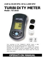
Figure 2 Maximum ambient temperature vs. probe load
Table 2 sc1000 controller capacity
Controller operating temperature (°C) Power available (watts) Controller capacity
40 55 2 SS7 sc plus 15 watts for other devices
50 35 2 SS7 sc plus 11 watts for other devices
55 25 1 SS7 sc plus 13 watts for other devices
38
40
44
48
52
56
42
46
50
54
58
Probe Load (watts)
sc 1000 Ambient T (°C)
Temp
20
22 24
26 28
30 32 34 36 38
40
42
44
46 48 50 52
54
56
58
Table 3 sc1000 component power consumption
Component Power consumption (watts)
Display module 10
Current output card 2.5 maximum load
Current input card 1.5
Relais card 1
Fieldbus module (Profibus) 2.5
Fieldbus module (Modbus) 0.5

Visit us at www.hach.com

9
Section 2 General information
2.1 Safety information
Please read this entire manual before unpacking, setting up or
operating this equipment. Pay attention to all danger and caution
statements. Failure to do so could result in serious injury to the
operator or damage to the equipment.
To ensure that the protection provided by this equipment is not
impaired, do not use or install this equipment in any manner other
than that specified in this manual.
2.1.1 Use of hazard information
DANGER
Indicates a potentially or imminently hazardous situation
which, if not avoided, could result in death or serious injury.
CAUTION
Indicates a potentially hazardous situation that may result in
minor or moderate injury.
Important Note: Information that requires special emphasis.
Note: Information that supplements points in the main text.
2.1.2 Precautionary labels
Read all labels and tags attached to the instrument. Personal injury
or damage to the instrument could occur if not observed. A symbol,
if noted on the instrument, will be included with a danger or caution
statement in the manual.
This symbol, if noted on the instrument, references the instruction manual for operation and/or safety information.
Electrical equipment marked with this symbol may not be disposed of in European public disposal systems after 12
August of 2005. In conformity with European local and national regulations (EU Directive 2002/96/EC), European
electrical equipment users must now return old or end-of life equipment to the Producer for disposal at no charge to
the user.
Note: For return for recycling, please contact the equipment producer or supplier for instructions on how to return
end-of-life equipment, producer-supplied electrical accessories and all auxiliary items for proper disposal.
This symbol, when noted on a product enclosure or barrier, indicates that a risk of electrical shock and/or
electrocution exists.
This symbol, if noted on the product, indicates the need for protective eye wear.
This symbol, when noted on the product, identifies the location of the connection for Protective Earth (ground).
This symbol, when noted on the product, identifies the location of a fuse or current limiting device.
This symbol, when noted on the product, identifies a risk of chemical harm and indicates that only individuals
qualified and trained to work with chemicals should handle chemicals or perform maintenance on chemical delivery
systems associated with the equipment.
This symbol, when noted on the product, indicated the presence of devices sensitive to Electro-static Discharge
(ESD) and indicated that care must be taken to prevent damage with the equipment.

10
General information
2.2 General product information
2.2.1 Instrument description
The Surface Scatter
®
7 sc (SS7 sc) Turbidimeter is a sensitive,
continuous-monitoring instrument designed for measuring turbidity
in fluids. The instrument design is based on the nephelometric
principle, where light scattered by particles suspended in the fluid is
measured to determine the relative amount of particulate matter in
the fluid. It meets all U.S. Environmental Protection Agency
(USEPA) design criteria, features an automatic-ranging digital
display and is capable of measuring turbidities from 0–9999 NTU.
Calibration is based on formazin, the primary turbidity reference
standard adopted by the APHA Standard Methods for the
Examination of Water and Wastewater and the USEPA. The
instrument consists of a control unit and a sample unit (Figure 3).
DANGER
The SS7 sc and SS7 sc-HST Turbidimeters are not designed
for use with samples that are flammable or explosive in nature.
If any sample solution other than water is used in this product,
test the sample/product compatibility to assure user safety
and proper product performance.
DANGER
The SS7 sc/sc controller platform product configuration is not
intended for installation in hazardous locations. See the
sc controller platform installation control drawing 58600-78 for
approved hazardous location sensors.
Figure 3 SS7 sc Turbidimeter
1 Sample unit 2 Control unit

11
General information
2.2.1.1 Controller
The SS7 sc and SS7 sc-HST operate in conjunction with an
sc controller platform. The controller enclosure houses the keypad,
display, microprocessor board and power supply components.
Operating controls and indicators are on the controller. The
controller is used to program the instrument for turbidity level alarm
set points and to perform diagnostic self-tests and
programming operations.
Sample turbidity is displayed continually by the digital display
during normal operation. Because of the automatic decimal point
positioning, no range selection is needed. Indicators of turbidity
level alarm conditions, certain critical system malfunctions or other
possible malfunctions are also on the controller.
Programmable alarm circuits provide three relay closures, both
normally open and normally closed, for selectable turbidity alarm
level set points. Set points can be programmed by the operator
anywhere within the overall range. The alarm circuits can be
programmed for Alarm, Feeder Control, Event Control, PWM
Control, Frequency Control and Warning. Refer to the sc controller
platform manual for setup and use of these different settings. An
alarm relay can be programmed in the sc controller platform to
control the optional Auto Flush Kit.
The controller is designed to meet NEMA 4X water-tight
requirements. It is constructed of corrosion-proof materials. It is
suitable for indoor installation. Mounting hardware is included with
the sc controller platform to provide the capability to wall mount,
pipe mount and panel mount the controller without affecting the
environmental integrity of the case. Electrical access holes are
sized for ½-in. conduit.
2.2.1.2 Sample unit
Sample flows through the sample unit (Figure 4) where sample
turbidity is measured. The sample unit enclosure contains all the
electronics for measuring the turbidity. A NEMA 12, corrosion-proof
case protects the optical components and hydraulics from industrial
environments and supplies the measurement signal to the control
unit. The case is designed for wall mounting with external
mounting blocks.
Hydraulic connections to the sample unit are at the bottom of the
enclosure. An air purge fitting is installed in the enclosure bottom.
Air purge is suggested to control condensation inside
the enclosure.

12
General information
Figure 4 SS7 sc components
1 Detector assembly (Cat. No. 71221-00) 5 Bulkhead fitting, 1-in. NPT (Cat. No. 40355-00)
2 Light source assembly (Cat. No. 45004-00) 6 Bulkhead fittings, ¾-in. NPT (Cat. No. 40311-00)
3 To sc controller platform 7 Turbidimeter body (Cat. No. 45002-00)
4 Cord grip (Cat. No. 61287-01)

13
General information
2.2.2 Surface Scatter 7 sc High Sample Temperature
The Surface Scatter 7 sc High Sample Temperature Turbidimeter
(SS7 sc-HST) has been designed for high sample temperature. The
basic design and principle of operation are the same as the
standard SS7 sc model. Differences between the standard and
HST models will be noted in this manual where appropriate.
Figure 5 Optical diagram
1 Detector assembly 5 Light beam 9 Instrument drain
2 Scattered light 6 Over-flowing sample 10 Refracted light
3 Lens 7 Overflow drain 11 Turbidimeter body
4 Lamp 8 Sample in 12 Reflected light

14
General information
Figure 6 SS7 sc-HSTcomponents
1 Flow multiplier 8 Cord grip (Cat. No. 61287-01)
2 ¾-in. hose 9 Bulkhead fitting, 1-in. NPT (Cat. No. 40355-00)
3 Threaded disk (Cat. No. 40299-00) with ¼-in. screw
(Cat. No. 7858-11)
10 Drain trap
4 Detector assembly (Cat. No. 71221-00) 11 1-in. NPT gravity drain
5 Vent cover (Cat. No. 40294-00) 12 Bulkhead fittings, ¾-in. NPT (Cat. No. 40311-00)
6 Light source assembly (Cat. No. 45004-00) 13 Turbidimeter body (Cat. No. 45002-00)
7 To sc controller platform

15
Section 3 Installation
DANGER
Only qualified personnel should conduct the tasks described
in this section of the manual. The SS7 sc/sc controller product
configuration is not intended for installation in
hazardous locations.
The tasks described in this section requires individuals to be
technically knowledgeable of the associated dangers. Burns,
shock, eye damage, fire and chemical exposure may occur if this
work is not done by qualified personnel. Always review appropriate
Material Safety Data Sheets (MSDS) before working with
chemicals.
3.1 Basic installation overview
1. Unpack the SS7 sc or SS7 sc-HST Turbidimeter (section 3.2).
2. Review the environmental requirements and select the
mounting location (section 3.3.2 on page 16).
3. Mount the sample unit (section 3.3.3 on page 17).
4. Install the optional heat exchanger, if required (section 3.3.4 on
page 19).
5. Install the 3-way ball valve, if required (section 3.3.5 on
page 20).
6. Connect the sample in, body drain and overflow drain
(section 3.5 on page 21).
7. Connect the air purge valve (section 3.6 on page 24).
8. Connect the sample unit to the controller to supply power to the
system (section 3.7.2 on page 24).
3.2 Unpacking the instrument
1. Remove the instrument from the shipping carton.
2. Verify that no visible damage has occurred during shipment. Be
sure the following items are included in the carton:
• Sample unit
• Instruction manual
• Installation kit items (Figure 7)
Contact the manufacturer immediately to report missing or
damaged items.

16
Installation
3.3 Mechanical installation
3.3.1 Environmental requirements
The SS7 sc and SS7 sc-HST enclosures are designed for
general-duty, indoor installation. Ambient temperatures within
specifications are allowed, but best performance will result if
temperature does not change rapidly. Do not mount in direct
sunlight. Shield from dripping water.
The controller enclosure is designed to protect the electronics from
typical conditions in water treatment and industrial facilities.
3.3.2 Selecting the installation location
Turbidimeters should always be located as close to the sampling
point as possible. The shorter the distance traveled by the sample
to the turbidimeter, the faster the turbidimeter can respond and
indicate changes in sample turbidity.
Dimensions and other installation information are shown in Figure 8
on page 18, Figure 9 on page 19 and Figure 10 on page 20. The
control and sample unit are designed for wall mounting. The
Figure 7 Installation kit items
1
1 Formazin stock solution, 4000 NTU, 500 mL 6 Washer, ¼ ID x 1.00 OD (4x)
2 Brush, cylinder, size 2 7 Adapter, barb fitting, ¾” NPT to ¾” ID hose barb (2x)
3 Calibration cup, SS7 sc 8 Adapter, barb fitting, 1” NPT to 1” ID hose
4 Light source alignment plate 9 Nipple, ¾” NPT
5 Wall mounting kit 10 Drain valve
1
See Section 8 Replacement parts and accessories on page 51.
Page is loading ...
Page is loading ...
Page is loading ...
Page is loading ...
Page is loading ...
Page is loading ...
Page is loading ...
Page is loading ...
Page is loading ...
Page is loading ...
Page is loading ...
Page is loading ...
Page is loading ...
Page is loading ...
Page is loading ...
Page is loading ...
Page is loading ...
Page is loading ...
Page is loading ...
Page is loading ...
Page is loading ...
Page is loading ...
Page is loading ...
Page is loading ...
Page is loading ...
Page is loading ...
Page is loading ...
Page is loading ...
Page is loading ...
Page is loading ...
Page is loading ...
Page is loading ...
Page is loading ...
Page is loading ...
Page is loading ...
Page is loading ...
Page is loading ...
Page is loading ...
Page is loading ...
Page is loading ...
Page is loading ...
Page is loading ...
Page is loading ...
Page is loading ...
Page is loading ...
Page is loading ...
/