Page is loading ...

—
ABB MEASUREMENT & ANALYTICS | OPERATING INSTRUCTION
Aztec ATS430
Turbidity sensor
Measurement made easy
Introduction
The ATS430 sensor is a rugged, reliable instrument designed to measure
the turbidity and suspended solids content of water.
The sensor is designed for use with the ABB AWT440 multi-input
transmitter featuring EZLink connection. EZLink enables new or
replacement sensors to be easily connected without the need to power
down the transmitter.
For more information
Publications for the associated Aztec AWT440
transmitter are available for free download from
www.abb.com/measurement (see links and
reference numbers below) or by scanning this code:
search for or click on:
Aztec AWT440 multi-input transmitter
Commissioning Instruction
CI/AWT440-EN
Aztec AWT440 multi-input transmitter
Data Sheet
DS/AWT440-EN
Sales
Service

2 OI/ATS430–EN Rev. H | Aztec ATS430 | Turbidity sensor
Contents
1 Health & Safety ....................................................... 3
1.1 Document symbols ............................................................3
1.2 Safety precautions ............................................................3
1.3 Potential safety hazards ..................................................3
1.3.1 Aztec ATS430 sensor – electrical ....................3
1.3.2 Aztec ATS430 sensor –
formazin used to calibrate the sensor ...............3
1.4 Safety standards ................................................................3
1.5 Product symbols ................................................................3
1.6 Product recycling and disposal (Europe only) .........3
1.7 Restriction of Hazardous Substances (RoHS) ..........3
2 System overview .....................................................4
3 Installation ................................................................ 5
3.1 Siting .................................................................................... 5
3.2 Sensor dimensions ........................................................... 5
3.3 Mounting / Cleaning options ....................................... 6
4 Sensor setup – first-time installation ............... 7
5 Sensor setup ............................................................8
5.1 Sensor Setup ...................................................................... 9
6 Calibration ..............................................................10
6.1 Calibrate menu ................................................................ 10
6.2 Sensor verification ........................................................... 11
6.2.1 Preparing the verification tool
and locking the sensor in place .......................... 11
6.2.2 Initiating the verification at the transmitter 12
6.3 Turbidity calibration ........................................................13
6.3.1 Calibration using optional calibration pot
ATS400740 .............................................................13
6.3.2 1-Point calibration ..............................................15
6.3.3 2-Point calibration ..............................................16
6.4 Suspended solids .............................................................17
6.4.1 Suspended solids calibration ..........................18
6.4.2 1-Point calibration ..............................................18
6.4.3 2-Point calibration ..............................................19
6.4.4 In process calibration ....................................... 20
6.4.5 Sample collection ............................................... 20
6.4.6 Collection complete ...........................................21
6.4.7 Manual coefficient ............................................. 22
6.5 Calibration log ................................................................. 22
7 Maintenance ............................................................ 23
7.1 Fitting and replacing the wiper blade .....................23
7.2 Diagnostic messages .................................................... 24
8 Specification .......................................................... 25
9 Spares and accessories ....................................... 26
9.1 ATS430 spares ................................................................. 26
9.2 ATS 430 accessories ..................................................... 26
9.3 EZLink digital sensor extension cables ................... 26
9.4 Mounting accessories .................................................... 26
9.5 Replacement parts for ATS430 sensor calibration
and verification kit (part no. ATS4000650) ................. 26
Appendix A – Principle of operation ..................... 27
A.1 Turbidity .............................................................................27
A.2 Suspended solids ............................................................27

Aztec ATS430 | Turbidity sensor | OI/ATS430–EN Rev. H 3
1 Health & Safety
1.1 Document symbols
Symbols that appear in this document are explained below:
1.2 Safety precautions
Be sure to read, understand and follow the instructions
contained within this manual before and during use of the
equipment. Failure to do so could result in bodily harm or
damage to the equipment.
1.3 Potential safety hazards
1.3.1 Aztec ATS430 sensor – electrical
The sensor operates on 24 V DC.
There are no hazardous voltages present in the sensor.
1.3.2 Aztec ATS430 sensor –
formazin used to calibrate the sensor
Sensor calibration (see Section 6.3.1, page 13) may require the
use of formazin.
1.4 Safety standards
This product has been designed to satisfy the requirements of
IEC61010-1:2010 3rd edition 'Safety Requirements for Electrical
Equipment for Measurement, Control and Laboratory Use' and
complies with US NEC 500, NIST and OSHA.
1.5 Product symbols
Symbols that may appear on this product are shown below:
1.6 Product recycling and disposal (Europe only)
1.7 Restriction of Hazardous Substances (RoHS)
WARNING – Bodily injury
This symbol in conjunction with the signal word
'WARNING' indicates a potentially dangerous situation.
Failure to observe this safety information may result in
death or severe injury.
IMPORTANT (NOTE)
This symbol indicates operator tips, particularly useful
information or important information about the product
or its further uses. The signal word 'IMPORTANT (NOTE)'
does not indicate a dangerous or harmful situation.
WARNING – Bodily injury Installation, operation,
maintenance and servicing must be performed:
— by suitably trained personnel only
— in accordance with the information provided in this
manual
— in accordance with relevant local regulations
DANGER – Formazin
Formazin is a polymerisation of 2 hazardous
constituents. Please conduct a full risk assessment
based on the supplier’s safety datasheet for formazin
before use.
Direct current supply only.
This symbol identifies a risk of chemical harm and
indicates that only individuals qualified and trained
to work with chemicals should handle chemicals or
perform maintenance on chemical delivery systems
associated with the equipment.
This symbol indicates the need for protective eye
wear.
This symbol indicates the need for protective hand
wear.
Recycle separately from general waste under the
WEEE directive.
Electrical equipment marked with this symbol may not
be disposed of in European public disposal systems
after 12 August 2005. To conform to European local and
national regulations (EU Directive 2002/96/EC),
European electrical equipment users must now return
old or end-of-life equipment to the manufacturer for
disposal at no charge to the user.
ABB is committed to ensuring that the risk of any
environmental damage or pollution caused by any of its
products is minimized as far as possible.
IMPORTANT (NOTE) For return for recycling, please
contact the equipment manufacturer or supplier for
instructions on how to return end-of-life equipment for
proper disposal.
The European Union RoHS Directive and subsequent
regulations introduced in member states and other
countries limits the use of six hazardous substances
used in the manufacturing of electrical and electronic
equipment. Currently, monitoring and control monitors
do not fall within the scope of the RoHS Directive,
however ABB has taken the decision to adopt the
recommendations in the Directive as the target for all
future product design and component purchasing.

4 OI/ATS430–EN Rev. H | Aztec ATS430 | Turbidity sensor
2 System overview
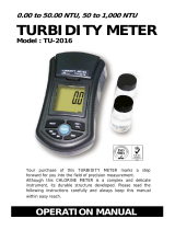
ATS430 sensor components are shown in Fig. 2.1:
Fig. 2.1 ATS430 sensor components
Item Feature
A
Sensor end cap
B Sensor body (see Table 2.2 for body and end cap
material options)
C Sensor cable, 5-way, including M12 connector
D EZLInk connector
Table 2.1 Sensor – component descriptions
Sensor no.* Body material Wiper Range
ATS430/A2A1
(1 m [3.2 ft] cable)
or
ATS430/A2A2
(10 m [32 ft] cable)
Stainless steel
316
Yes
(viton)
0 to 4000
NTU
ATS430/A1A1
(1 m [3.2 ft] cable)
or
ATS430/A1A2
(10 m [32 ft] cable)
Stainless steel
316
No 0 to 4000
NTU
ATS430/A3A1
(1 m [3.2 ft] cable)
or
ATS430/A3A2
(10 m [32 ft] cable)
Titanium No 0 to 4000
NTU
*All sensors conform to the ISO 7027 standard.
Table 2.2 Sensor body options / part numbers

Aztec ATS430 | Turbidity sensor | OI/ATS430–EN Rev. H 5
3 Installation
3.1 Siting
3.2 Sensor dimensions
IMPORTANT (NOTE)
— The sensor is supplied with a protective cover on the
end cap. The cover must be removed before the
sensor can be operational.
— When installing the sensor, ensure that the front
face of the sensor is submerged to at least 30 cm
(11.81 in.) and the sensor is at least 5 cm (1.96 in.)
away from any surface in all directions.
— When using extension cables, protect the
connections using heat shrink (for example,
HISA-18/6-PEX-CL or equivalent).
Fig. 3.1 Siting the sensor
Dimensions in mm (in.).
Fig. 3.2 Sensor dimensions
Max.
210 m (64 ft.)
Sample surface
5 cm
(1.96 in.)
min.
5 cm
(1.96 in.)
min.
30 cm
(11.81 in.)
min.
40 (1.57)
180
(
7.09
)
150
(
5.90
)
10
(
0.40
)
1000 (39)
or
10000 (393)
nominal
1 in. BSP thread
5 cm
(1.96 in.) min.

6 OI/ATS430–EN Rev. H | Aztec ATS430 | Turbidity sensor
3.3 Mounting / Cleaning options
Sensor mounting / cleaning options are shown in Table. 3.1 /
Fig. 3.3:
Item Mounting option
A Open channel mounting kit:
— ATS4000768, suitable for floor/wall (surface) mounting
(ATS4000720 chain mounting kit available separately)
B Wall mounting accessory:
— ATS4000700, suitable for 40 mm / 1.25 in dia dip pole
C Dip pole assembly (supplied with 40 mm dia pole):
— ATS4000750: 2.5 m (8.2 ft) straight
— ATS4000716: 2.5 m (8.2 ft) 90° bend
— ATS4000719: 2.5 m (8.2 ft) 45° bend
Dip pole mounting adaptor kits
(to attach to user-supplied pole)
— ATS4000751: for attachment to 40 mm dia or
1.25 in NB pole (straight)
— ATS4000710: for attachment to 1.25 in NB pole
(90° bend)
— ATS4000711: for attachment to 1.25 in NB pole
(45° bend)
— ATS4000714: for attachment to 40 mm dia. pole
(90° bend)
— ATS4000715: for attachment to 40 mm dia. pole
(45° bend)
Note. Handrail mounting brackets are not supplied with
this kit and must be purchased separately.
D Open tank flanged dip mount:
— ATS4000785, for mounting on user-supplied
mounting bracket
E Wiper arm protective shroud assembly:
— ATS4000725
F Flow cell pipeline mount:
— ATS4000741, suitable for wall / surface mounting
(includes wall mounting clip)
G Handrail mounting bracket – swivel / tilt action:
— ATS4000762 for 1.25 in NB dip pole,
suitable for 42 or 51 mm (1.7 or 2.0 in) dia. handrail
— ATS4000763 for 40 mm dia dip pole,
suitable for 42 or 51mm (1.7 or 2.0 in) dia. handrail
H Handrail mounting bracket – tilt action:
— ATS4000760 for 40mm or 1.25 in dia dip pole, suitable
for 42 or 51mm (1.7 or 2.0 in) dia handrail
I Retractable insertion assembly:
— ATS4000780, maximum pressure 10 bar (145 psi), for
mounting on user-supplied flange: BS EN 1092-1,
Type 01B, DN50, PN16, stainless steel 316L or similar.
Maximum distance from flange sealing face to pipe I/D
must not exceed 70 mm (2.75 in.).
Table 3.1 ATS430 sensor mounting / cleaning options
Fig. 3.3 ATS430 sensor mounting / cleaning options
F
G
A
C
B
D
E
H
User-supplied
mounting
bracket

Aztec ATS430 | Turbidity sensor | OI/ATS430–EN Rev. H 7
4 Sensor setup – first-time installation
To perform a first-time installation (Easy Setup menu):
1. Connect a new or replacement sensor to the transmitter’s
EZLink connector – see transmitter Operating instructions
OI/AWT440-EN.
The following prompt is displayed identifying the new /
replacement sensor (S1 to S4):
2. To enter Easy Setup level, press the key
(below the icon).
The Easy Setup start screen is displayed:
Press the key (below the Select prompt).
3. To enter Easy Setup level, press the key
(below the Select icon).
4. Press the key (below the Edit prompt) to change the
default value to the required value / selection.
5. Press the key (below the Next prompt) to accept the
value / selection displayed and advance to the next
configuration parameter.
The following Configuration parameters are set at Easy
Setup level:
—Tag
— PV Type
— Units
— Range High
— Range Low
— Clean Interval
— Filter Type
— Analogue outputs and alarms
6. Continue with configuration of the required parameters.
On completion the Easy Setup start screen is displayed:
7. To exit Easy Setup, press the key (below the Exit
prompt) to display the Operator Page.
Pressing the key (below the Select prompt) re-enters the
Easy Setup level where parameters can be reviewed or
modified after 1st time connection.
After completing the Easy Setup level, pressing the
or key enters the Advanced Configuration level, where
all available sensor and transmitter parameters can be
reviewed or modified.
IMPORTANT (NOTE)
Perform this procedure when a new / replacement
sensor is connected to the transmitter for the first time
only. For existing sensors, see Section 5, page 8.
ATS400
New Sensor Sx
Detected
Start Easy
Setup ?
00-00-2014
Menu
Easy Setup
Exit Select
IMPORTANT (NOTE)
Refer to Section 5.1, page 9, for parameter details – not
all parameters in Section 5.1 are displayed at Easy Setup
level.
IMPORTANT (NOTE)
To re-configure an existing sensor (after first-time
installation), enter the Configuration level (see
Section 5.1, page 9) via the Operator Page – refer to
transmitter Operating instructions
OI/AWT440-EN for
Operator Page details and navigation.
Menu
Easy Setup
Exit Select

8 OI/ATS430–EN Rev. H | Aztec ATS430 | Turbidity sensor
5 Sensor setup
1. Connect the ATS430 sensor to the transmitter’s EZLink
connector – see transmitter Operating instruction
OI/AWT440-EN.
2. At the AWT440 transmitter, press the key to display the
Operator Page menu, then select Enter Configuration to
display the Access Level page.
Use the key to select the Advanced menu item and
press the key (below the Select prompt).
If the Sensor Setup menu is not displayed use the /
keys to scroll to it:
Press the key (below the Select prompt).
3. The Sensor Setup page is displayed:
Ensure Sx :Turb TSS is highlighted and press the key
(below the Select prompt).
The Sx :Turb TSS: Turbidity menu page is displayed:
4. Proceed with sensor setup – see Section 6.1, page 10
for parameter options.
IMPORTANT (NOTE)
Perform this procedure on existing sensor(s) only.
Sensors are setup / configured individually. If installing a
new / replacement sensor, refer to Section 4, page 7.
Exit Select
Menu
Sensor Setup
1
2
3
Sensor Setup
Sx: Turb TSS
Back Select
1
2
3
Sx :TURB TSS
Tag
PV Type
Units
Range High
Range Low
Clean Interval
Back
Select

Aztec ATS430 | Turbidity sensor | OI/ATS430–EN Rev. H 9
5.1 Sensor Setup
*Displayed only if Clean Interval is NOT set to Off AND Clean
Mechanism is set to External.
**Displayed only if Clean Type is set to Pulsed.
Used to set the sensor tag, operational range, filtering parameters and clean interval.
Menu
Sensor Setup
Exit
Select
Menu Comment Default
S1 (to 4) : TURBIDITY Select the turbidity sensor to set up.
Tag Enter an alphanumeric sensor tag (16 characters maximum) to
identify the sensor on the Operator Pages.
TAG1
PV Type Select measurement type.
Note. If a change is made the I/O sources are reset.
Turbidity / Suspended Solids
Turbidity
Turb Units Select the turbidity units: NTU / FNU NTU
SS Units Select the units for suspended solids: mg/l / ppm
For readings above 1000 mg/l (ppm) the units change to g/l (ppt).
mg/l
Range High Set the span value in Chart and Bargraph views. 4000 NTU (turbidity)
1000 mg/l (suspended
solids)
Range Low Set the zero value in Chart and Bargraph views. 0 NTU (turbidity)
0 mg/l (suspended
solids)
Filter Type Select the signal filtering type:
Off / Low / Medium / High / Bubble Reject
Off
Clean Interval Set the interval between cleans:
Off / 15 mins / 30 mins / 45 mins / 1 to 24 Hours
Off
Clean Mechanism None (for non wiper versions), Wiper (for wiper versions) or
External. The external option allows the transmitter to control
an external cleaning device through the digital I/O lines.
Note. Refer to the Aztec ADS430 EZCLEAN operating
instructions (
OI/ADS430/EZCLN-EN) for an example of
the use of this facility.
Clean Type* Set the clean type: Continuous / Pulsed. Continuous
Clean On Time* Set the duration of the clean: 1 to 60 s 30 secs
Clean Off Time* / ** Set the duration between cleans: 1 to 60 s 30 secs
Recovery Time* Set the time delay between the completion of cleaning and the
display of a new reading on the operator page: 1 to 10 min
1 min
Clean Duration* Displays the total duration of the clean:
Clean Type set to Continuous = Clean on Time + Recovery Time
Clean Type set to Pulsed = (Clean on Time + Clean Off Time)
x Number of Pulses + Recovery Time
Clean Output* Displays the output signal the clean is assigned to.
This can be set to relay 1 to 6 or digital output 1 to 6.
No Assignment
Reset Wiper Lifetime Available only for sensors with wipers. Use to restart the wiper
lifetime counter after wiper replacement.
Restore Defaults Returns all settings back to default values. N/A

10 OI/ATS430–EN Rev. H | Aztec ATS430 | Turbidity sensor
6 Calibration
This section describes how to calibrate the sensor and involves
measuring the sensor's sensitivity to turbidity and / or
suspended solids by exposing the sensor to samples of known
turbidity or suspended solids content.
Calibrations are initiated via the Cal prompt displayed on the
main page or via the Operator pages or Calibrate and Advanced
menu items on the Access Level page – refer to transmitter
Operating instructions
OI/AWT440-EN for all transmitter menu
options.
6.1 Calibrate menu
IMPORTANT (NOTE)
— Do not perform a calibration until the sensor and
transmitter are installed and ready for operation.
— Before removing the sensor for calibration
purposes, set the currents outputs and alarms to
Hold (enabled via the Operator Menu / Manual Hold
function).
Used to calibrate the sensor.
Access to the Calibrate menu is via the Calibrate and Advanced levels only.
Note. During calibration, current outputs and alarms are set to Hold automatically if
Hold Outputs is enabled (see below).
– Refer to Section 6.2, page 11 to perform a sensor verification.
– Refer to Section 6.3, page 13 to perform a turbidity calibration.
– Refer to Section 6.4, page 17 to perform a suspended solids calibration.
Menu
Calibrate
Exit
Select
Menu Comment Default
S1(to 4) : TURB TSS Select the turbidity sensor to calibrate.
Sensor Verification
Turbidity Calibration
1-Point Cal General purpose span calibration.
2-Point Cal Calibration for better accuracy.
Suspended Solids Cal
1-Point Cal General purpose span calibration.
2-Point Cal Calibration for better accuracy.
Sample Collection Sample collection in progress.
Collection Complete Sample collection completed.
Manual Coefficient Enter the coefficient that relates the turbidity of the sample
to its suspended solids content.
Restore Defaults Restores default values to their factory settings.
Hold Outputs Enable / disable the Hold Outputs function. If enabled, the
current outputs and alarm functions are held during calibrations.
Enabled

Aztec ATS430 | Turbidity sensor | OI/ATS430–EN Rev. H 11
6.2 Sensor verification
6.2.1 Preparing the verification tool and locking the sensor
in place
The verification tool can be used to verify sensor operation as
an alternative to using formazin. Using the verification tool
eliminates the need to handle potentially hazardous chemicals
(formazin) during routine verification.
Referring to Fig. 6.1:
1. Select a verification puck with the NTU value suitable for the
application – the NTU value is printed on puck label
A.
2. Remove protective cap
B from puck C.
3. Align slot
D (opposite puck label A) with sprung ball
screw
E located within the bore of the lower section of
verification tool
F.
4. Press puck
C into place taking care not to touch the upper
surface and confirm a puck of the correct NTU value has
been fitted – the NTU value of the puck is visible through
front aperture
G.
5. Pour a few drops of coupling agent
H onto the puck
surface, near the centre of the circle.
6. Ensure slider
I is in the unlocked position.
7. Insert sensor
J into verification tool F and align the
(2 opposing) holes
K with notch L on the verification tool
top cap.
8. Push sensor
J down until the holes K in the sensor body
are within the top cap, then push slider
I to the locked
position to lock sensor
J in place.
9. Refer to Operating instruction
OI/AWT440-EN and initiate a
verification routine.
10. When the verification routine is complete, carefully wipe
puck
C and verification tool F clean, refit puck cap B
and store all items into the case supplied with the kit.
IMPORTANT (NOTE)
— Ensure the verification tool carrier is kept clean and
any dirt is removed after each use.
— Ensure the sensor is clean of dirt and fouling prior to
insertion into the verification tool (step 7).
— Take care not to damage the surface of verification
pucks. When using the puck in locations where grit
or sand may be present, ensure the sensor is
thoroughly clean before inserting it into the
verification tool. Any debris on the front face of the
sensor will prevent the puck making full contact with
the sensing area and result in a reading error as well
as possible damage to the puck.
IMPORTANT (NOTE)
Sensors with accessories connected:
— sensor
J is shown with a standard cable
attached. If accessories (such as dip pole, chain
adaptor) are connected there is no need to
disconnect them. Verification can be performed
with accessories in place. For flow cell mounted
sensors, unscrew the flow cell adaptor from the
sensor then slide it up the cable.
Aligning sensors fitted with wiper:
— orientate the sensor with the wiper blade to the
front (open cut-out) to ensure correct
alignment with the puck. This also ensures
correct alignment with the locking plate peg. To
avoid damage to the wiper arm, wiping is
disabled automatically while the sensor is
inserted in the verification tool.
IMPORTANT (NOTE) When pushing the sensor into
the verification tool body (step 8), ensure the sensor
is inserted straight so that the sensor face is placed
directly onto the puck surface.
Fig. 6.1 Using the verification tool
Label on rear face of tool – shows
sensor fitting / preparation
Locked
Unlocked
Ensure the coupling
agent is applied near
the centre of the
circle. For the wiper
puck, this is near the
straight edge.

12 OI/ATS430–EN Rev. H | Aztec ATS430 | Turbidity sensor
6.2.2 Initiating the verification at the transmitter
1. At the Calibrate level, press the key (below the Select
prompt):
The sensor selector menu is displayed:
Highlight the sensor to be verified (for example
S1:Turb TSS) and press the key (below the Select
prompt).
2. The menu options for S1:Turb TSS are displayed:
3. Use the / keys to select Sensor Verification
and press the key (below the Select prompt).
The Sensor Verification screen is displayed:
4. Press the key (below the Edit prompt) to enter the value
of the verification puck.
5. Enter the turbidity value printed on the puck label and press
the key (below the OK prompt).
The Start Verification screen is displayed:
Ensure the sensor is inserted in the verification tool
(see Section 6.2.1, page 11) and press the key
(below the Continue prompt) to start the verification
routine. (To Abort verification, press the key).
6. The Verification progress screen is displayed:
If the verification process completes successfully, a
verification successful message (Procedure Pass) is
displayed:
Menu
Calibrate
Exit Select
Calibrate
S1:Turb TSS
Back Select
Hold Outputs
S1:Turb TSS
Sensor Verification
Back Select
Turbidity Cal
Suspended Solids Cal
Restore Defaults
Sensor Verification
Next Edit
Verification Value
4000 NTU
1
2
3
Verification Value
Next OK
04000
NTU
Max 4000
Min 0.000
Verification
Abort Continue
Start Verification?
1000 NTU
Verification
Abort
PV 1001 NTU
STD 1000 NTU
Verification
Exit
PV 1001 NTU
STD 1000 NTU
Procedure Pass

Aztec ATS430 | Turbidity sensor | OI/ATS430–EN Rev. H 13
7. If the verification fails, a verification failure message
(Procedure Failed) is displayed:
This may indicate that the sensor requires calibration.
6.3 Turbidity calibration
Used to calibrate the sensor to measure turbidity. There are two
possible calibration modes:
— 1-Point calibration, refer to Section 6.3.2, page 15
— 2-Point calibration, refer to Section 6.3.3, page 16
A 1-point calibration adjusts the Calibration Slope and is
suitable for general operation.
A 2-point calibration is recommended when measuring low
turbidity values (below 50 NTU). The Offset and Slope are
adjusted resulting in improved accuracy at low turbidity
concentrations.
When performing calibrations for measuring low turbidity
values (below 50 NTU), ensure the sensor reading is not affected
by light scattered by the calibration solution container. Use a
large container (minimum 1 litre) and ensure that the sensor is
immersed by no more than 5 cm below the solution surface and
is at least 5 cm from the container walls.
For low level applications that use the ABB Flowcell
(ATS4000741), use the Calibration Pot (part no. ATS4000740) to
calibrate the sensor. See Section 6.3.1.
When calibrating using high NTU values of formazin, stir the
solution continuously throughout the procedure. If the
calibration is performed outside, shield the calibration vessel
from direct sunlight.
Before starting the calibration process, ensure that the vessel
and the sensor are cleaned and dried thoroughly to avoid
contaminating calibration solutions. Before adding formazin to
the vessel, ensure the solution is mixed thoroughly by rocking
(not shaking) the bottle gently.
6.3.1 Calibration using optional calibration pot ATS400740
The calibration pot (part no. ATS4000740) is recommended for
use in the following situations:
—
When performing a calibration in direct sunlight.
The calibration pot excludes ambient light that can affect
the measurement.
—
For low level applications (less than 50 NTU) that use the ABB
flowcell (ATS4000741)
The interior properties (dimensions and surface finish) of
the flowcell and calibration pot are comparable, resulting in
a matched calibration.
—
For high concentration calibrations, when the use of large
quantities of formazine solution is not desirable.
The calibration pot requires only 200 ml of calibration
solution.
Do not use the calibration pot in low level applications (less than
50 NTU) that either do not use the flowcell or where the sensor
is mounted more than 5 cm away from any surface, as the
surface light scattering in the calibration pot could result in an
offset in the reading.
Referring to Fig. 6.2, page 14:
1. Slide cap
A onto sensor B until the cap is close to the top
of the sensor.
2. Hold cap
A and press sensor B down using an
anti-clockwise twisting motion until sensor
B connects.
For sensors installed in a flow cell, the flow cell thread
adaptor can be used instead of the calibration pot cap.
Alternatively, unscrew the adaptor and slide back to allow
the cap to fit onto the sensor.
3. Carefully pour 200 ml (6.76 ounce [US, liquid]) of formazin
F into calibration pot G.
4. Carefully slide sensor / cap assembly
H into calibration
pot
G until fully inserted.
DANGER – Formazin
Formazin is a polymerisation of 2 hazardous
constituents. Please conduct a full risk assessment
based on the supplier’s safety datasheet for formazin
before use.
Verification
Exit
PV 1400 NTU
STD 1000 NTU
Procedure Failed
IMPORTANT (NOTE)
— When inserting the sensor into the calibration
solution take care not to trap air bubbles in the front
face of the sensor. For sensors with wiper, perform
a wipe before proceeding with calibration.
— Sensors with accessories connected:
— sensor
B (Fig. 6.2, page 14:) is shown with a
standard cable attached. If accessories (such as
dip pole, chain adaptor) are connected the
calibration can still be performed with them in
place.
IMPORTANT (NOTE)
Cap
A has 2 sprung-loaded ball screws C that
engage with 2 holes
D in the top ring of sensor B.
Confirm correct alignment by checking that 2
grooves
E on the top face of cap A align with
holes
D / ball screws C when cap is connected.

14 OI/ATS430–EN Rev. H | Aztec ATS430 | Turbidity sensor
5. Perform a sensor calibration at the transmitter:
— see Section 6.3.2, page 15 for a 1-point calibration
— see Section 6.3.3, page 16 for a 2-point calibration.
6. When the calibration is complete, withdraw sensor / cap
assembly
H from calibration pot G. Remove cap A from
sensor
B (a combined pull and twist action is the easiest
withdrawal method). Rinse all items with water and dry
thoroughly with tissue (not supplied).
7. Dispose of formazin solution safely in accordance with local
regulations.
Fig. 6.2 Calibration using the optional calibration pot
200 ml (6.76 fl. oz)
formazin

Aztec ATS430 | Turbidity sensor | OI/ATS430–EN Rev. H 15
6.3.2 1-Point calibration
For the 1-point calibration only a span value is used. The span
value can be provided by a verification puck, a formazin solution
or an AMCO standard.
1. At the Calibrate level, press the key (below the Select
prompt):
The sensor selector menu is displayed:
Highlight the sensor to be calibrated (for example
S1:Turbidity TSS) and press the key (below the Select
prompt).
2. The menu options for S1:Turbidity TSS are displayed:
3. Use the / keys to select Turbidity Cal and press
the key (below the Select prompt).
The Turbidity Cal screen is displayed:
4. Press the key (below the Edit prompt).
The Calibration Type screen is displayed:
5. Use the / keys to select 1-Point Cal and press the
key (below the OK prompt).
Press the key (below the Next prompt).
The Turbidity / Offset screen is displayed:
For most cases a zero offset is suitable. However, in
situations where an offset was previously determined
during a 2-point calibration, it is possible to retain the
previously measured offset during the 1-point calibration.
6. To select the required offset press the key (below the
Edit prompt).
The Offset / Remove Offset | Retain Offset screen is
displayed:
7. Use the / keys to select Retain Offset and press
the key (below the OK prompt) to confirm the selection
and use the existing offset, or select Remove Offset to
remove the offset (an offset of 0 NTU is assumed).
Menu
Calibrate
Exit Select
Calibrate
S1:Turbidity TSS
Back Select
Hold Outputs
S1:Turb TSS
Sensor Verification
Back Select
Turbidity Cal
TSS Cal
Restore Defaults
Turbidity Cal
Next Edit
Calibration Type
1-Point Cal
Calibration Type
1-Point Cal
Cancel OK
2-Point Cal
Turbidity
Next Edit
Offset
Remove Offset
Offset
Cancel OK
Remove Offset
Retain Offset

16 OI/ATS430–EN Rev. H | Aztec ATS430 | Turbidity sensor
The Turbidity | Calibration Value screen is displayed where
the calibration value can be modified by pressing the
key (below the Edit prompt).
When the required value is set, press the key (below the
Next prompt).
8. Once the value shown on screen matches the span value,
insert the sensor in the verification tool or solution and
press the key (below the Continue prompt).
The calibration process screen is displayed – the calibration
can be cancelled at any time during the process by pressing
the key (below the Abort prompt):
9. If the calibration is successful the final screen displays the
new slope. Press the key (below the Exit prompt) to
return to the main menu.
The 1-point calibration is now complete.
6.3.3 2-Point calibration
2 Solutions are used for a 2-point calibration. This calibration is
used when more accuracy is needed over a given range, using
calibration solutions at either end of the desired range.
1. At the Calibrate level, press the key (below the Select
prompt):
The sensor selector menu is displayed:
2. Highlight the sensor to be calibrated and press the key
(below the Select prompt).
The menu options for S1: Turb TSS are displayed:
3. Use the / keys to select Turbidity Cal and press the
key (below the Select prompt).
The Turbidity screen is displayed:
Turbidity
Next Edit
Calibration Value
200.0 NTU
Calibrate
Abort Continue
200.0 NTU
Start Cal?
Place in High Sol
Calibrate
Abort
200 NTU
56.00 mV
Settling-Please Wait
Menu
Calibrate
Exit Select
Calibrate
S1:Turb TSS
Back Select
Hold Outputs
S1:Turb TSS
Back Select
Sensor Verification
Turbidity Cal
TSS Cal
Restore Defaults
Turbidity Cal
Next Edit
Calibration Type
1-Point Cal

Aztec ATS430 | Turbidity sensor | OI/ATS430–EN Rev. H 17
4. Press the key (below the Edit prompt).
The Calibration Type screen is displayed:
5. Use the / keys to select 2-Point Cal and press the
key (below the OK prompt) to start the 2-point
calibration. The Turbidity / Low Solution Value screen is
displayed where the first point value can be entered:
Press the key (below the Next prompt).
Press the key (below the Edit prompt) to enter the value
of the lower calibration point. Press the key (below the
OK prompt). Press the key (below the Next prompt) to
set the value and display the Second Point Value screen.
6. On the Turbidity / High Solution Value screen press the
key (below the Edit prompt) to enter the value of the higher
calibration point.
7. Place the sensor in the lower calibration solution, press the
key (below the OK prompt), press the key (below the
Next and press the key (below the Continue prompt).
The calibration process screen is displayed – the calibration
can be cancelled at any time during the process by pressing
the key (below the Abort prompt):
8. When acquisition is complete remove the sensor from the
first calibration point, clean and insert the sensor into the
second calibration point. Clean and dry the sensor
thoroughly, to avoid cross contamination of the calibration
solutions. Press the key (below the Continue prompt) to
start data acquisition.
9. If the calibration fails a message is displayed indicating the
reason for failure. If the calibration is successful the final
screen displays the new slope. Press the key (below the
Exit prompt) to return to the main menu.
The 2-point calibration is now complete.
6.4 Suspended solids
There are 4 possible calibration modes for suspended solids:
— 1-Point calibration: assumes that there is no zero offset,
so a single point is used to calculate the linear relation
between turbidity and suspended solids – refer to
Section 6.4.2, page 18
— 2-Point calibration: two solutions of known suspended
solids concentrations are used to determine the linear
relation between turbidity and suspended solids – refer
to Section 6.4.3, page 19
— In-Process calibration: used in situations where it is not
possible to remove the sensor from the process. A grab
sample is taken from the process for laboratory
determination of the suspended solids content, and the
sensor stores the turbidity value being read at the time
the sample was taken – refer to Sections 6.4.4, page 20
to 6.4.6, page 21
— Manual coefficient: allows the user to input a coefficient
obtained from data analyzed in the lab – refer to
Section 6.4.7, page 22.
Calibration Type
1-Point Cal
Cancel OK
2-Point Cal
Turbidity
Next Edit
Low Solution Value
0.000 NTU
Turbidity
Next Edit
High Solution Value
200.0 NTU
Calibrate
Abort Continue
Start Cal?
Place in Low Sol
0.000 NTU
Calibrate
Abort
PV 0.000 NTU
mV -0.00 mV
Settling-Please Wait
Calibrate
Abort Continue
Start Cal?
200 NTU
Calibrate
Abort Continue

18 OI/ATS430–EN Rev. H | Aztec ATS430 | Turbidity sensor
6.4.1 Suspended solids calibration
To perform a suspended solids calibration:
1. At the Calibrate level, press the key (below the Select
prompt):
The sensor selector menu is displayed:
2. Highlight the sensor to be calibrated and press the key
(below the Select prompt). The menu options for
calibration are displayed:
3. Use the / keys to select TSS Cal and press the
key (below the Select prompt) to enter the calibration
menus.
6.4.2 1-Point calibration
A solution of a known turbidity and suspended solids content is
used to calibrate the sample.
1. At the Calibration Type screen, press the key (below the
Edit prompt), use the / keys to select 1-Point Cal
and press the key (below the OK prompt):
The Suspended Solids / High Solution Value screen is
displayed. Press Next:
2. Press the key (below the Next prompt) to start the
calibration.
3. In the following screen, press the key (below the Edit
prompt) to enter the suspended solids content of the
calibration sample.
4. Press the key (below the OK prompt) once the value has
been entered.
Menu
Calibrate
Exit Select
Calibrate
S1:Turbidity TSS
Back Select
Hold Outputs
S2:Turbidity SS
Back Select
Sensor Verification
Turbidity Cal
TSS Cal
Restore Defaults
Calibration Type
1-Point Cal
Cancel OK
2-Point Cal
Sample Collection
Collection Complete
Suspended Solids
Next Edit
High Solution Value
0.000 mg/l
1
2
3
Span Solution Value
Next OK
0.000
mg/l
Max 99999
Min 0.000

Aztec ATS430 | Turbidity sensor | OI/ATS430–EN Rev. H 19
5. Place the sensor in the sample when prompted and press
the key (below the Continue prompt) to start the
calibration:
The calibration progress window is displayed. When
acquisition is complete a screen displays the calibration
coefficient. Press the key (below the Exit prompt) to
return to the main menu.
The calibration is now complete.
6.4.3 2-Point calibration
Two solutions are used for a 2-point calibration. This calibration
is used when more accuracy is needed over a given range, using
calibration solutions at either end of the required range.
1. At the Calibration Type screen, use the / keys to
select 2-Point Cal and press the key (below the OK
prompt):
2. On the next screen, press the key (below the Next
prompt).
3. On the Low Solution Value screen press the key (below
the Edit prompt) to enter the value of the lower calibration
point. Press the key (below the Next prompt) once the
value is entered.
4. On the 2nd Point Value screen press the key (below the
Edit prompt) to enter the value of the higher calibration
point. Press the key (below the Next prompt) once the
value is entered.
5. Place the sensor in the lower calibration point and press
the key (below the Continue prompt).
The calibration process screen is displayed – the calibration
can be cancelled at any time during the process by pressing
the key (below the Abort prompt):
6. On completion, remove the sensor from the first calibration
point, clean and insert the sensor into the second
calibration point. Press the key (below the Continue
prompt) to start data acquisition.
7. If the calibration fails a message is displayed indicating the
reason for failure. If the calibration is successful the next
screen displays the new slope. Press the key (below the
Exit prompt) to return to the main menu.
The 2-point calibration is now complete.
Calibrate
Abort Continue
Start Cal?
Place in High Sol
1.000 mg/l
Calibration Type
2-Point Cal
Cancel OK
1-Point Cal
Sample Collection
Collection Complete
Manual Coefficient
Suspended Solids
Next Edit
Low Solution Value
0.000 mg/l
Suspended Solids
Next Edit
High Solution Value
1.000 mg/l
Calibrate
Abort Continue
Start Cal?
Place in Low Sol
0.000 mg/l
Calibrate
Abort
PV 0.000 mg/l
PV 0.000 NTU
Settling-Please Wait
Calibrate
Abort Continue
Start Cal?
Place in High Sol
1.000 mg/l

20 OI/ATS430–EN Rev. H | Aztec ATS430 | Turbidity sensor
6.4.4 In process calibration
In process calibration is used when it is not possible to remove
the sensor from the process to perform the calibration. In this
calibration mode the actual sample is used to calibrate the
sensor.
The in process calibration takes place in two steps. During the
first step a grab sample is taken from the process, and the
sensor records the turbidity of the sample at that time. The
suspended solids content of the grab sample is then measured
in the laboratory and entered into the transmitter during the
second step.
Due to the inherent variability of both the turbidity and
suspended solids measurements, using a single point to
calibrate the suspended solids measurement can lead to sudden
jumps in the suspended solids value reported by the sensor.
(The ATS430 sensor supports an adaptive calibration mode,
which mitigates the occurrence of such jumps.) – refer to
AN/ANAINST/021-EN for details of adaptive calibration.
1. At the Calibration Type screen, use the / keys to
select Sample Collection and press the key (below the
OK prompt):
2. Proceed to Section 6.4.5 (Sample collection) to start the
first part of the calibration.
6.4.5 Sample collection
1. This is the first step of the calibration. On the next screen,
press the key (below the Next prompt).
Performing this step erases any sample collection
performed previously. Only the last sample collection
performed is stored in the sensor.
2. On the following screen press the key (below the
Continue prompt) to start the data collection. The grab
sample should be taken as close to the sensor as possible
during this period.
The calibration process screen is displayed – the acquisition
can be cancelled at any time during the process by pressing
the key (below the Abort prompt):
3. Once the acquisition is complete, Press the key (below
the Exit prompt) to return to the main menu.
The value of the sample turbidity is now stored.
4. Proceed to Section 6.4.6 (Sample collection) to start the
second part of the calibration once the suspended solids
value has been determined.
Calibration Type
Sample Collection
Cancel OK
1-Point Cal
2-Point Cal
Collection Complete
Manual Coefficient
Collect Sample
Abort Continue
Start Collection?
Collect Sample
Abort
PV 0.000 mg/l
NTU 2000 NTU
Settling-Please Wait
Collect Sample
Exit
Procedure Complete
PV 0.000 mg/l
NTU 2000 NTU
/