Page is loading ...

Catalog Number 58600-18
Hach sc100™ Controller
USER MANUAL
February 2005, Edition 5
© Hach Company, 2003–2005. All rights reserved. Printed in the U.S.A. eac/dp

Visit http://www.hach.com

3
Table of Contents
Section 1 Specifications............................................................................................................................................... 5
Section 2 General Information ..................................................................................................................................... 7
2.1 Safety Information ..................................................................................................................................................... 7
2.1.1 Use of Hazard Information............................................................................................................................... 7
2.1.2 Precautionary Labels....................................................................................................................................... 7
2.2 General Product Information ..................................................................................................................................... 7
Section 3 Installation..................................................................................................................................................... 9
3.1 Mechanical Installation............................................................................................................................................ 11
3.1.1 Controller Dimension Illustrations .................................................................................................................. 11
3.1.2 Mounting the Controller.................................................................................................................................. 13
3.2 Wiring Safety Information........................................................................................................................................ 15
3.2.1 Electrostatic Discharge (ESD) Considerations............................................................................................... 15
3.3 Electrical Installation................................................................................................................................................ 15
3.3.1 Installation in Conduit..................................................................................................................................... 16
3.3.2 Installation Using a Power Cord..................................................................................................................... 16
3.3.3 Wiring for Power at the Controller .................................................................................................................. 17
3.4 Alarms and Relays .................................................................................................................................................. 20
3.4.1 Connecting the Relays................................................................................................................................... 20
3.4.2 Connecting the Analog Outputs..................................................................................................................... 21
3.5 Connecting/Wiring the sc Sensor............................................................................................................................ 22
3.5.1 Connecting the sc Sensor in a Non-hazardous Location............................................................................... 22
3.5.2 Connecting the sc Sensor to a Controller in a Hazardous Location............................................................... 24
3.6 Wiring the Digital Gateway ...................................................................................................................................... 25
3.7 Connecting the Optional Digital Output................................................................................................................... 25
Section 4 Operation..................................................................................................................................................... 29
4.1 Using the Keypad .................................................................................................................................................... 29
4.2 Controller Display Features ..................................................................................................................................... 30
4.2.1 Important Key Presses................................................................................................................................... 30
4.3 System Setup ........................................................................................................................................................ 31
4.3.1 Adjusting Display Contrast............................................................................................................................. 31
4.3.2 Specifying the Displayed Language............................................................................................................... 31
4.2.2 Software Text Abbreviations........................................................................................................................... 31
4.3.3 Setting the Time and Date ............................................................................................................................. 32
4.4 Setting up System Security ..................................................................................................................................... 33
4.4.1 Setting the Passcode..................................................................................................................................... 33
4.4.2 Editing the Passcode ..................................................................................................................................... 33
4.5 Output Options ........................................................................................................................................................ 34
4.5.1 Navigating to the Output Options Menu......................................................................................................... 34
4.5.2 Hold/Transfer Outputs .................................................................................................................................... 34
4.5.3 Release Outputs ............................................................................................................................................ 35
4.6 Relay Options.......................................................................................................................................................... 35
4.6.1 Navigating to the Relay Options Menu........................................................................................................... 35
4.7 Data Event Logging Options.................................................................................................................................... 35
4.8 Digital Network Options........................................................................................................................................... 36
4.9 System Setup Menu................................................................................................................................................ 36
4.10 Test/Maint Menu.................................................................................................................................................... 40
Section 5 Maintenance................................................................................................................................................ 41
5.1 Cleaning the Controller............................................................................................................................................ 41
5.2 Fuse Replacement .................................................................................................................................................. 41

4
Table of Contents
Section 6 Replacement Parts and Accessories........................................................................................................43
6.1 Replacement Items..................................................................................................................................................43
6.2 Accessories..............................................................................................................................................................43
Section 7 Compliance Information.............................................................................................................................45
Section 8 How to Order ...............................................................................................................................................47
Section 9 Repair Service.............................................................................................................................................48
Section 10 Limited Warranty.......................................................................................................................................49

5
Section 1 Specifications
Specifications are subject to change without notice.
Component Description
Microprocessor-controlled measuring unit with measured value display, temperature
display, and menu-driven system
Controller Operating
Temperature
–20 to 60 °C (–4 to 140 °F); 95% relative humidity, non-condensing with sensor/network
card load <7 W; –20 to 40 °C (–4 to 104 °F) with sensor /network card load <25 W
Controller Storage
Temperature
–20 to 70 °C (–4 to 158 °F); 95% relative humidity, non-condensing
Enclosure NEMA 4X/IP66 metal enclosure with a corrosion-resistant finish
Power Requirements
AC Powered sc100 model: 100–230 VAC ±10%, 50/60 Hz; Power 15 W with 7 W
sensor/network card load, 37 W with 25 W sensor/network card load
24 VDCpowered sc100 model: 24 VDC –15%, +20%; Power 16W with 7W
sensor/network card load, 34 W with 25 W sensor/network card load
Pollution Degree/
Installation Category
II; II
Outputs
Two (Analog (4–20 mA)) outputs, maximum impedance 500 ohm. Optional digital network
connection. IrDA digital connection.
Relays
Three SPDT, user-configured contacts rated 100–230 VAC, 5 Amp resistive maximum for
the ac powered sc100 and 24 VDC, 5A resistive maximum for the dc powered sc100.
Controller Dimensions ½ DIN—144 x 144 x 150 mm (5.7 x 5.7 x 5.9 inches)
Controller Weight 1.6 kg (3.5 lb)
Certifications
CE approved (with all sensor types)
Listed for use in general locations to UL and CSA safety standards by ETL (with all sensor
types)
Listed for use in Class I, Division 2 hazardous locations to FM & CSA safety standards by
ETL (with specified sensor types, per Control Drawing 58600-78

Visit us at www.hach.com

7
Section 2 General Information
2.1 Safety Information
Please read this entire manual before unpacking, setting up, or operating this equipment.
Pay attention to all danger and caution statements. Failure to do so could result in serious
injury to the operator or damage to the equipment.
To ensure that the protection provided by this equipment is not impaired, do not use or
install this equipment in any manner other than that specified in this manual.
2.1.1 Use of Hazard Information
DANGER
Indicates a potentially or imminently hazardous situation which, if not avoided,
could result in death or serious injury.
CAUTION
Indicates a potentially hazardous situation that may result in minor or moderate
injury.
Important Note: Information the requires special emphasis.
Note: Information that supplements points in the main text.
2.1.2 Precautionary Labels
Read all labels and tags attached to the instrument. Personal injury or damage to the
instrument could occur if not observed
2.2 General Product Information
The controller enclosure is NEMA4X/IP66-rated and has a corrosion-resistant finish
designed to withstand corrosive environmental constituents such as salt spray and
hydrogen sulfide. The controller display shows the current reading plus a secondary
measurement such as temperature if connected to a single sensor, or two readings with
their corresponding secondary measurement readings when two sensors are connected.
Installation instructions for the controller are presented in this manual. If a system with a
sensor and a controller has been purchased, complete information for installation and
operation is also presented in the sensor system manual.
This symbol, if noted on the instrument, references the instruction manual for operation and/or safety information.
This symbol, when noted on a product enclosure or barrier, indicates that a risk of electrical shock and/or
electrocution exists.
This symbol, if noted on the product, indicates the need for protective eye wear.
This symbol, when noted on the product, identifies the location of the connection for Protective Earth (ground).
This symbol, when noted on the product, identifies the location of a fuse or current limiting device.

Visit us at www.hach.com

9
Section 3 Installation
DANGER
Only qualified personnel should conduct the installation tasks described in this
section of the manual. This equipment is suitable for use in non-hazardous
locations or Class 1, Division 2, Groups A, B, C, D Hazardous Locations with
specified sensors and options when installed per the Hazardous Location
Installation Control Drawing on page 10. Always refer to the Control Drawing and
applicable electrical code regulations for proper installation instructions.
DANGER
Explosion hazard. Substitution of components may impair suitability for Class 1,
Division 2. Do not replace any component unless power has been switched off or
the area is known to be non-hazardous.
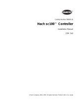
Figure 1 Components of a Basic System
1. Controller 6. Lock washer, ¼-inch I.D. (4), Cat. No. 8H1336
2. Mounting foot for panel mounting (2), Cat. No. 1000B4F3222 7. Flat washer, ¼-inch I.D. (4), Cat. No. 8H1346
3. Bracket for panel & pipe mounting,
Cat. No. 1000C4F3217-101
8. Pan head screws (4), M6 x 1.0 x 20 mm,
Cat. No. 5867400
4. Gasket for panel mounting, Neoprene,
Cat. No. 1000A4F3249-101
9. Pan head screws (4), M6 x 1.0 x 100 mm,
Cat. No. 5867500
5. Hex nut, M6 (4), Cat. No. 5867300 10. Pan head screws (4), M6 x 1.0 x 150 mm,
Cat. No. 5867600
Table 1 Customer-supplied Items
Item
14-AWG wire for electrical power connections in conduit or 115 or 230 V ac power cord plus a NEMA 4X-rated strain relief
High-quality, shielded instrumentation cable for connecting the analog outputs plus a NEMA 4X-rated strain relief.
Mounting hardware for the sensor (available from the manufacturer, order separately). See the sensor manual.
Sun shield for mounting configurations where the sun strikes the front of the display.
Common hand tools
1
3
4
8
5
6
7
9
10
2
sc100

10
Installation
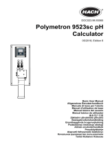
Figure 2 Hazardous Location Installation Control Drawing
PROBE, REF.TABLE 1
SEE NOTE 3
PROBE, REF.TABLE 1
SEE NOTE 3
TABLE 1
PROBE DESCRIPTION PART NO.
LDO PROBE w/10m CABLE
57900-01
CONTACTING CONDUCTIVITY PROBE w/6 m CABLE
34XXXA
INDUCTIVE CONDUCTIVITY PROBE w/6 m CABLE 3700 SERIES
DIFFERENTIAL PH PROBE w/4.5 m CABLE PD SERIES RD SERIES
COMBINATION PH PROBE w/4.5 m CABLE PC SERIES RC SERIES
TABLE 2
NETWORK INTERFACE DESCRIPTION PART NO.
RS 232 NETWORK CARD
59200-00
RS 485 NETWORK CARD 59200-01
AQUATREND NETWORK CARD 59200-02
PROFI BUS NETWORK CARD 59200-03
PRIOR TO CHANGING
APPROVAL REQUIRED
REGULATORY AGENCY
THIS DRAWING
NORTH AMERICAN HAZARDOUS (CLASSIFIED) LOCATION
NORTH AMERICAN HAZARDOUS (CLASSIFIED) LOCATION
NON-HAZARDOUS (CLASSIFIED) LOCATION
NON-HAZARDOUS (CLASSIFIED) LOCATION
CLASS I DIV.2 GROUPS A, B, C, D
CLASS I, ZONE 2, GROUP IIC, T4
CLASS I, ZONE 2, GROUP IIC, T4
1. WIRING METHODS MUST BE IN ACCORDANCE
WITH NEC, ANSI/NFPA 70, ARTICLE 504
CEC C22.1-94, SECTION 18 & ANSI/ISA
RP 12.6
2. CONNECTIONS FROMTHE sc100 DEVICES IN
NON-HAZARDOUS LOCATIONTO BE IN 1/2"
(1.3 cm) CONDUIT
3. TWO SENSORS MAXIMUMWITH ANY SENSOR
CONFIGURATION SHOWN.
INPUT 100-230V, 50/60 Hz or 24 VDC
INPUT 100-230V, 50/60 Hz or 24 VDC
OR
20 AMP BREAKER OR SWITCH
20 AMP BREAKER OR SWITCH
D
E
E
CONTROL DRAWING,
HAZ LOCATION, sc100
HAZ LOCATION, sc100
58600-78
58600-78
KCT
GR
NONE
NONE
1 OF 1
SEE TABLE 3
3
D
2
ENGR
DIMENSIONS ARE IN INCHES
DIMENSIONS ARE IN INCHES
8
3
.XX
D
REVISIONS
REVISIONS
6 4
78
DESCRIPTION
DESCRIPTION
DWN
THIRD ANGLE PROJECTION
THIRD ANGLE PROJECTION
DWG. NO.
SCALE
57
.XXX
.XXX
B
REV
D
DO NOT SCALE THIS DWG
DO NOT SCALE THIS DWG
ANGLES
1
NOTICE - Hach Company claims proprietary rights in the information disclosed on this drawing. It is issued in confi-
dence for engineering information only and may not,in whole or in part,be used to manufacture anything, whether or
not shown hereon,reproduced or disclosed to anyone without direct permission from Hach Company.
UNLESS OTHERWISE SPECIFIED
UNLESS OTHERWISE SPECIFIED
SIZE
SHT
MATL.
4
A
B
REL
REV
TITLE
CC
A
APPROVED
6
.X
1
TOLERANCES ARE AS FOLLOWS:
TOLERANCES ARE AS FOLLOWS:
Hach Company
Hach Company
5600 Lindbergh Dr.
5600 Lindbergh Dr.
Loveland, CO 80539
Loveland, CO 80539
5
TABLE 3
EXTENSION CABLE DESCRIPTION PART NO.
1 m EXTENSION CABLE 61224-01
7 m EXTENSION CABLE 57960-01
15 m EXTENSION CABLE 57961-01
31 m EXTENSION CABLE 57962-01
TABLE 4
GATEWAY DESCRIPTION PART NO.
DIGITAL GATEWAY, DIFF.PH 61205-00
DIGITAL GATEWAY, COMBO PH 61206-00
DIGITAL GATEWAY, CONTACTING CONDUCTIVITY 61207-00
DIGITAL GATEWAY, INDUCTIVE CONDUCTIVITY 61208-00
DIGITAL GATEWAY
REF.TABLE 4
REVISED PER R-2023-04
REVISED PER R-2023-04
REVISED PER R-1253-05
REVISED PER R-1253-05
SC100
CONTROLLER
WITH NETWORK
WITH NETWORK
CARD
REF.TABLE 2
UPTO 3 SWITCHED RELAY LOADS
FROM sc100 RELAY CONTACTS
RATED 30VAC OR 42.2 VDC
@ 5 AMP (MAX.)
UPTO 3 SWITCHED RELAY LOADS
FROM sc100 RELAY CONTACTS
RATED 100-230V, 50/60 HZ,
5 AMP (MAX.)
INPUT = 100 - 230V, 50/60 Hz INPUT = 24VDC
NETWORKTERMINAL
(e.g. COMPUTER)
OR 4-20 mA (2)TERMINAL
(e.g. CHART RECORDER)

11
Installation
3.1 Mechanical Installation
Install in an environment that is protected from corrosive fluids.
3.1.1 Controller Dimension Illustrations
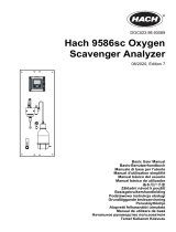
Figure 3 Controller Dimensions
Figure 4 Controller Mounting Dimensions
sc100
144.0 mm (5.67 inches) 150.0 mm (5.91 inches)
144.0 mm (5.67 inches)
80.27 mm
(3.16 inches)
144.02 mm (5.67 inches)
80.27 mm
(3.16 inches)
144.02 mm
(5.67 inches)
72.01 mm
(2.84 inches)
72.01 mm
(2.84 inches)
40.14 mm (1.58 inches)
M6 x 1.0
40.14 mm
(1.58 inches)

12
Installation
Figure 5 Panel Mount Cut-out Dimensions
Figure 6 Conduit Hole Dimensions
133 mm (5.25 )inches
144 mm (5.67 )inches
ref only()
135 mm
(5.31 )inches
144 mm
(5.67 )
()
inches
ref only
67.4 mm
(2.65 )inches
72 mm
(2.835 )inches
ref only()
66.67 mm (2.625 )inches
75 mm (2.955 )inches
(ref only)
6.35 mm (0.25 inch)
15.24 mm (0.60 inch)
28.57 mm (1.125 inches)
75.07 mm (2.955 inches)
127 mm
(5.00 inches)
150 mm
(5.91 inches)
(ref only)
99.31 mm
(3.91 inches)
50.8 mm
(2.00 inches)
28.57 mm (1.125 inches)
68.96 mm (2.715 inches)
25.4 mm (1.00 inch)
25.4 mm (1.00 inch)
144 mm (5.67 inches)

13
Installation
3.1.2 Mounting the Controller
Attach the controller to a rail or wall or mount it in a panel. Supplied mounting hardware is
shown in Figure 7, Figure 8, and Figure 9.
Figure 7 Vertical or Horizontal Pipe Mounting the Controller
Figure 8 Wall Mounting the Controller
1. Controller 4. Flat washer, ¼-inch I.D. (4), Cat. No. 8H1346
2. Pipe (vertical or horizontal) 5. Hex nut, M6 (4), Cat. No. 5867300
3. Bracket, pipe mounting, Cat. No. 1000C4F3217-101 6. Pan head screw, M6 x 1.0 x 100 mm (4), Cat. No. 5867400
1. Controller 4. Pan head screw, M6 x 1.0 x 20 mm (4), Cat. No. 5867400
2. Bracket, Cat. No. 1000C4F3217-101 5. Customer-supplied hardware for wall mounting
3. Lock washer, ¼-inch I.D., Cat. No. 8H1336
3
1
2
4
5
6
3
4
2
1
5

14
Installation
Figure 9 Panel Mounting the Controller
To remove the sensor connectors before inserting the controller enclosure into the panel
cut-out:
1. Disconnect the wires at terminal block J5, see Figure 19 on page 24.
2. Loosen and remove the nut securing the sensor connector inside the enclosure.
Remove the sensor connector and wires. Repeat step 1 and 2 for the other sensor
connector.
3. After the controller is in place in the panel, reinstall the sensor connectors and
reconnect the wiring to terminal J5 as shown in Figure 19 on page 24.
1. Controller 7. Lock washer, ¼-inch I.D., (4) Cat. No. 8H1336
2. Gasket, Neoprene, panel mount,
Cat. No. 1000A4F3249-101
8. Hex nut (4), Cat. No. 5867300
3. Panel (maximum thickness is 9.5 mm (
3
/8 inch)) 9. Flat washer (4), Cat. No. 8H1346
4. Mounting Foot (2), Cat. No. 1000B4F3222 10. Pan head screw, M6 x 1.0 x 150 mm (4),
Cat. No. 5867600
5. Mounting bracket, controller, Cat. No. 1000C4F3217-101 11. It may be necessary to remove the sensor connectors.
see procedure below.
6. Pan head screw (4), Cat. No. 5867400
1
2
3
4
5
6
7
8
11
9
8
10

15
Installation
3.2 Wiring Safety Information
When making any wiring connections to the sc100 Controller, the following warnings and
must be adhered to, as well as, any warnings and notes found throughout the individual
installation sections. For more safety information refer to Safety Information on page 7.
DANGER
Always disconnect power to the instrument when any making electrical
connections.
3.2.1 Electrostatic Discharge (ESD) Considerations
Important Note: To minimize hazards and ESD risks, maintenance procedures not
requiring power to the analyzer should be performed with power removed.
Delicate internal electronic components can be damaged by static electricity, resulting in
degraded instrument performance or eventual failure.
The manufacturer recommends taking the following steps to prevent ESD damage to
your instrument:
• Before touching any instrument electronic components (such as printed circuit cards
and the components on them) discharge static electricity from your body. This can be
accomplished by touching an earth-grounded metal surface such as the chassis of an
instrument, or a metal conduit or pipe.
• To reduce static build-up, avoid excessive movement. Transport static-sensitive
components in anti-static containers or packaging.
• To discharge static electricity from your body and keep it discharged, wear a wrist
strap connected by a wire to earth ground.
• Handle all static-sensitive components in a static-safe area. If possible, use anti-static
floor pads and work bench pads.
3.3 Electrical Installation
DANGER
This equipment is suitable for use in non-hazardous locations or Class 1, Division
2, Groups A, B, C, D Hazardous Locations with specified sensors and options when
installed per the Hazardous Location Installation Control Drawing on page 10.
Always refer to the Control Drawing and applicable electrical code regulations for
proper installation instructions.
High-voltage wiring for the controller is conducted behind the high voltage barrier in the
controller enclosure. The barrier must remain in place unless a qualified installation
technician is installing wiring for power, alarms, or relays. See Figure 10 for barrier
removal information.

16
Installation
Figure 10 Removing Voltage Barrier
3.3.1 Installation in Conduit
In hard-wired electrical applications, the power and safety ground service drops for the
instrument must be 18 to 12 AWG. See Figure 11 on page 16 for strain relief and conduit
opening sealing plug information. See section 3.3.3 on page 17 for wiring information.
3.3.2 Installation Using a Power Cord
DANGER
Use of a power cord is not acceptable in Class 1, Division 2 Hazardous Location
Installation (see Hazardous Location Installation Control Drawing on page 10).
A sealing-type strain relief to maintain the NEMA 4X/IP66 environmental rating and a
power cord less than 3 meters (10 feet) in length with three 18-gauge conductors
(including a safety ground wire) can be used, see Replacement Parts and Accessories on
page 43. See Figure 11 on page 16 for strain relief and conduit opening sealing plug
assembly. See section 3.3.3 on page 17 for wiring information.
Figure 11 Using the Optional Strain Relief and Conduit Plug
1. High voltage barrier 2. Unsnap the barrier latch then pull out to remove the barrier.
NCNCNC
COMCOMCOM
NO
F1
F2
NONO
RELAY CRELAY B
RELAY B
RELAY A
RELAY A
1
1
+ DATA
+ DATA
+ OUT 2
+ OUT 2
– DATA
– OUT 2
SERVICE REQUEST
SHIELD/CHASSIS GND
+ V
+ V
+ OUT 1
+ OUT 1
GND
– OUT 1
2
2
3
3
4
4
5
5
6
PROBES
ANALOG OUTPUTS
ANALOG OUTPUTS
PCB
CONNECTOR
PCB
CONNECTOR
FIELD WIRING
INSULATION MUST
BE RATED TO
80° C MINIMUM
FIELD WIRING
INSULATION MUST
BE RATED TO
80° C MINIMUM
DANGER - EXPLOSION HAZARD
DANGER - RISQUE D'EXPLOSION
DO NOT DISCONNECT WHILE CIRCUIT IS LIVE
UNLESS AREA IS KNOWN TO BE NON-HAZARDOUS.
NE PAS DEBRANCHER TANT QUE LE EST SOUS
TENSION, A MONIS QU'IL NE S'AGISSE D'UN
EMPLACEMENT NON-DANGEROUX
J1
J2
J4
NETWORK
INTERFACE
CARD
J3
J5
J6
U5
U9
S1
NCNCNC
COMCOMCOM
NO
F1
F2
NONO
RELAY CRELAY BRELAY BRELAY ARELAY A
1
1
+ DATA+ DATA
+ OUT 2+ OUT 2
– DATA
– OUT 2
SERVICE REQUEST
SHIELD/CHASSIS GND
+ V+ V
+ OUT 1+ OUT 1
GND
– OUT 1
2
2
3
3
4
4
5
5
6
PROBES
ANALOG OUTPUTSANALOG OUTPUTS
PCB
CONNECTOR
PCB
CONNECTOR
FIELD WIRING
INSULATION MUST
BE RATED TO
80° C MINIMUM
FIELD WIRING
INSULATION MUST
BE RATED TO
80° C MINIMUM
DANGER - EXPLOSION HAZARD
DANGER - RISQUE D'EXPLOSION
DO NOT DISCONNECT WHILE CIRCUIT IS LIVE
UNLESS AREA IS KNOWN TO BE NON-HAZARDOUS.
NE PAS DEBRANCHER TANT QUE LE EST SOUS
TENSION, A MONIS QU'IL NE S'AGISSE D'UN
EMPLACEMENT NON-DANGEROUX
J1
J2
J4
NETWORK
INTERFACE
CARD
J3
J5
J6
U5
U9
S1
2
1
1. Power cord strain relief 2. Conduit strain relief 3. Conduit opening sealing plug
2
3

17
Installation
3.3.3 Wiring for Power at the Controller
DANGER
Explosion hazard. Do not connect or disconnect electrical components or circuits
to the equipment unless power has been switched off or the area is known to be
non-hazardous.
DANGER
Do not connect AC power to a sc100 24 VDC powered model.
The sc100 can be purchased as either an 100–230 VAC powered model or a 24 VDC
powered model. Follow the appropriate wiring instructions per the purchased model.
Important Note: A protective earth (PE) ground connection is required by the sc100 for
both 100–230 VAC and 24 VDC wiring applications. Failure to connect a good PE ground
connection can result in shock hazards and poor performance due to electromagnetic
interferences. ALWAYS connect a good PE ground to the sc100 terminal.
The controller can be wired for line power by hard-wiring in conduit or wiring to a power
cord. Regardless of the wire used, the connections are made at the same terminals. A
local disconnect designed to meet local electrical code is required and must be identified
for all types of installation. See Figure 14 and Figure 15 on page 19 for suggested local
disconnect configurations.
1. Obtain appropriate fittings with NEMA 4X/IP66 environmental rating.
2. Loosen the screws using a phillips-head screwdriver and open the hinged controller
cover.
3. Remove the high-voltage barrier (see Figure 10 on page 16).
4. Insert the wires through the strain relief fitting or conduit hub located in the right-rear
access hole in the bottom of the enclosure. Tighten the strain relief if used, to secure
the cord.
5. Properly prepare each wire (Figure 12) and insert each wire into the terminal
according to Table 2 or Table 3. Tug gently after each insertion to ensure the
connection is secure.
6. Seal any unused openings in the controller box with conduit opening sealing plugs.
7. Reinstall the high-voltage barrier and latch to secure.
Figure 12 Proper Wire Preparation and Insertion
1. Strip ¼-inch of insulation. 2. Seat insulation against connector with no bare wire exposed.
1
2

18
Installation
The DC power source that supplies power to the 24 VDC powered sc100 must maintain
voltage regulation within the specified 24 VDC –15% +20% voltage limits. The DC power
source must also provide adequate protection against surges and line transients.
Figure 13 sc100 Wiring Connections
Table 2 AC Power Wiring Information (sc100 AC powered model only)
Terminal Number Terminal Description Wire Color Code for North America Wire Color Code for Europe
1 Hot (L1) Black Brown
2 Neutral (N) White Blue
3 Protective Earth (PE) Green Green w/yellow tracer
Table 3 DC Power Wiring Information (sc100 24 VDC powered model only)
Terminal Number Terminal Description Wire Color Code for North America Wire Color Code for Europe
1 +24 V dc Red Red
2 24 V dc return Black Black
3 Protective Earth (PE) Green Green w/yellow tracer
1. J1—Network connector 8. Sensor connector
2. J2—Header for optional network interface card 9. Sensor connector
3. J5—Relay A connector 10. J6—Analog output (4–20 mA) connector
4. J6—Relay B connector 11. J5—Sensor connector for hard-wiring
5. J7—Relay C connector 12. Position for network interface card
6. Fuses (F1, F2) 13. Service port
7. J8—Power connections 14. Sensor terminator selector/service port configuration
a. AC Power connection (AC powered sc100 model only)
b. DC Power connection (24 VDC sc100 model only)
NCNCNC
COMCOMCOM
NO
F1
F2
NONO
RELAY CRELAY BRELAY A
J1
J2
J4
NETWORK
INTERFACE
CARD
J3
J5
J6
U5
U9
S1
6
7
7a
7b
14
12
13
312
89
45
11 10
+24 VDC
+24
VDC
–24 VDC
–24
VDC

19
Installation
Figure 14 Local Disconnect for Power Cord
Figure 15 Local Disconnect for Hard-wired Line Power
1. Power terminal 2. Power cord strain relief
1. Power terminal 2. Conduit strain relief
NCNCNC
COMCOMCOM
NO
F1
F2
NONO
RELAY CRELAY B
RELAY B
RELAY A
J1
J2
J4
NETWORK
INTERFACE
CARD
J3
J5
J6
U5
U9
S1
1
2
NCNCNC
COMCOMCOM
NO
F1
F2
NONO
RELAY CRELAY B
RELAY B
RELAY A
J1
J2
J4
NETWORK
INTERFACE
CARD
J3
J5
J6
U5
U9
S1
1
2

20
Installation
3.4 Alarms and Relays
DANGER
Explosion hazard. Do not connect or disconnect electrical components or circuits
to the equipment unless power has been switched off or the area is known to be
non-hazardous.
DANGER
For Class 1, Division 2 Hazardous Location installations, refer to the Control
Drawing (Figure 2 on page 10) for permanent connection requirements for the alarm
relays.
DANGER
Exposure to some chemicals may degrade the sealing properties of materials used
in the following devices: Relays K1, K2, and K3. Periodic inspection of these
devices is recommended to check for degradation.
The controller is equipped with three unpowered relays rated 100–230 VAC, 50/60 Hz,
5 amp resistive maximum. See the sensor manual for relay setup details.
3.4.1 Connecting the Relays
DANGER
Relay loads must be resistive. User must externally limit current to the relays to
5 Amps by use of a fuse or breaker.
DANGER
Power and relay terminals are designed for only single wire termination. Do not use
more than one wire in each terminal.
The relay connector accepts 18–12 AWG wire (as determined by load application). Wire
gauge less than 18 AWG is not recommended.
The Normally Open (NO) and Common (COM) relay contacts will be connected when an
alarm or other condition is active. The Normally Closed (NC) and Common relay contacts
will be connected when an alarm or other condition is inactive or when power is removed
from the controller.
AC Line (100–230 V) Powered sc100’s
AC line powered sc100 controllers contain three relays designed for connection to AC
MAINS circuits (i.e., voltages greater than 30V-RMS, 42.2V-PEAK or 60 V dc). Refer to
Figure 16 for connection information. The relay wiring compartment is not designed for
voltage connections below these levels. Relays must not be powered from the same wiring
used to power the controller.
24 VDC Powered sc100
The 24 VDC sc100 controller contains three relays designed for connection to LOW
voltage circuits (i.e., voltages less than 30V-RMS, 42.2V-PEAK or 60 V dc). Refer to
Figure 16 for connection information. The wiring compartment is not designed for voltage
connections above these levels. Relay must not be powered from the same wiring used to
power the controller.
/