Page is loading ...

User Guide
CTR 8
Switcher Accessories
Eight Input Contact Closure to RS-232 Control Module
68-2524-01 Rev. B
03 16

Safety Instructions
Safety Instructions • English
WARNING: This symbol, , when used on the product, is intended to
alert the user of the presence of uninsulated dangerous voltage within
the product’s enclosure that may present a risk of electric shock.
ATTENTION: This symbol, , when used on the product, is intended
to alert the user of important operating and maintenance (servicing)
instructions in the literature provided with the equipment.
For information on safety guidelines, regulatory compliances, EMI/EMF
compatibility, accessibility, and related topics, see the Extron Safety and
Regulatory Compliance Guide, part number 68-290-01, on the Extron
website, www.extron.com.
Instructions de sécurité • Français
AVERTISSEMENT : Ce pictogramme, , lorsqu’il est utilisé sur le
produit, signale à l’utilisateur la présence à l’intérieur du boîtier du
produit d’une tension électrique dangereuse susceptible de provoquer
un choc électrique.
ATTENTION : Ce pictogramme, , lorsqu’il est utilisé sur le produit,
signale à l’utilisateur des instructions d’utilisation ou de maintenance
importantes qui se trouvent dans la documentation fournie avec le
matériel.
Pour en savoir plus sur les règles de sécurité, la conformité à la
réglementation, la compatibilité EMI/EMF, l’accessibilité, et autres sujets
connexes, lisez les informations de sécurité et de conformité Extron, réf. 68-
290-01, sur le site Extron, www.extron.com.
Sicherheitsanweisungen • Deutsch
WARNUNG: Dieses Symbol auf dem Produkt soll den Benutzer
darauf aufmerksam machen, dass im Inneren des Gehäuses dieses
Produktes gefährliche Spannungen herrschen, die nicht isoliert sind
und die einen elektrischen Schlag verursachen können.
VORSICHT: Dieses Symbol auf dem Produkt soll dem Benutzer in der
im Lieferumfang enthaltenen Dokumentation besonders wichtige Hinweise
zur Bedienung und Wartung (Instandhaltung) geben.
Weitere Informationen über die Sicherheitsrichtlinien, Produkthandhabung,
EMI/EMF-Kompatibilität, Zugänglichkeit und verwandte Themen finden Sie in
den Extron-Richtlinien für Sicherheit und Handhabung (Artikelnummer
68-290-01) auf der Extron-Website, www.extron.com.
Instrucciones de seguridad • Español
ADVERTENCIA: Este símbolo, , cuando se utiliza en el producto,
avisa al usuario de la presencia de voltaje peligroso sin aislar dentro del
producto, lo que puede representar un riesgo de descarga eléctrica.
ATENCIÓN: Este símbolo, , cuando se utiliza en el producto, avisa
al usuario de la presencia de importantes instrucciones de uso y
mantenimiento recogidas en la documentación proporcionada con el
equipo.
Para obtener información sobre directrices de seguridad, cumplimiento
de normativas, compatibilidad electromagnética, accesibilidad y temas
relacionados, consulte la Guía de cumplimiento de normativas y seguridad
de Extron, referencia 68-290-01, en el sitio Web de Extron, www.extron.com.
Инструкция по технике безопасности • Русский
ПРЕДУПРЕЖДЕНИЕ: Данный символ, , если указан
на продукте, предупреждает пользователя о наличии
неизолированного опасного напряжения внутри корпуса
продукта, которое может привести к поражению
электрическим током.
ВНИМАНИЕ: Данный символ, , если указан на продукте,
предупреждает пользователя о наличии важных инструкций
по эксплуатации и обслуживанию в руководстве,
прилагаемом к данному оборудованию.
Для получения информации о правилах техники безопасности,
соблюдении нормативных требований, электромагнитной
совместимости (ЭМП/ЭДС), возможности доступа и других
вопросах см. руководство по безопасности и соблюдению
нормативных требований Extron на сайте Extron: www.extron.com,
номер по каталогу - 68-290-01.
安全说明 • 简体中文
警告: 产品上的这个标志意在警告用户该产品机壳内有暴露的危险 电压,
有触电危险。
注意: 产品上的这个标志意在提示用户设备随附的用户手册中有
重要的操作和维护(维修)说明。
关于我们产品的安全指南、遵循的规范、EMI/EMF 的兼容性、无障碍
使用的特性等相关内容,敬请访问 Extron 网站 www.extron.com,参见
Extron 安全规范指南,产品编号 68-290-01。
安全記事 • 繁體中文
警告: 若產品上使用此符號,是為了提醒使用者,產品機殼內存在著
可能會導致觸電之風險的未絕緣危險電壓。
注意 若產品上使用此符號,是為了提醒使用者,設備隨附的用戶手冊中有重
要的操作和維護(維修)説明。
有關安全性指導方針、法規遵守、EMI/EMF 相容性、存取範圍和相關主題的詳
細資訊,請瀏覽 Extron 網站:www.extron.com,然後參閱《Extron 安全性
與法規遵守手冊》,準則編號 68-290-01。
安全上のご注意
• 日本語
警告: この記号 が製品上に表示されている場合は、筐体内に絶縁されて
いない高電圧が流れ、感電の危険があることを示しています。
注意: この記号 が製品上に表示されている場合は、本機の取扱説明書
に 記載されている重 要な 操作と保 守(整備)の指 示についてユーザー の 注
意を喚起するものです。
安全上のご注意、法規厳守、EMI/EMF適合性、その他の関連項目に
つ い て は 、エ ク スト ロ ン の ウェブ サ イト www.extron.comよ り 『 Extron Safety
and Regulatory Compliance Guide』 ( P/N 68-290-01) をご覧ください。
안전 지침 • 한국어
경고: 이 기호 가 제품에 사용될 경우, 제품의 인클로저 내에 있는
접지되지 않은 위험한 전류로 인해 사용자가 감전될 위험이 있음을
경고합니다.
주의: 이 기호 가 제품에 사용될 경우, 장비와 함께 제공된 책자에 나와
있는 주요 운영 및 유지보수(정비) 지침을 경고합니다.
안전 가이드라인, 규제 준수, EMI/EMF 호환성, 접근성, 그리고 관련 항목에
대한 자세한 내용은 Extron 웹 사이트(www.extron.com)의 Extron 안전 및
규제 준수 안내서, 68-290-01 조항을 참조하십시오.

FCC Class A Notice
This equipment has been tested and found to comply with the limits for a Class A digital device,
pursuant to part15 of the FCC rules. The ClassA limits provide reasonable protection against harmful
interference when the equipment is operated in a commercial environment. This equipment generates,
uses, and can radiate radio frequency energy and, if not installed and used in accordance with the
instruction manual, may cause harmful interference to radio communications. Operation of this
equipment in a residential area is likely to cause interference; the user must correct the interference at
his own expense.
NOTE: This unit was tested with shielded I/O cables on the peripheral devices. Shielded cables
must be used to ensure compliance with FCC emissions limits.
For more information on safety guidelines, regulatory compliances, EMI/EMF compatibility,
accessibility, and related topics, see the “Extron Safety and Regulatory Compliance
Guide” on the Extron website.
Copyright
© 2016 Extron Electronics. All rights reserved.
Trademarks
All trademarks mentioned in this guide are the properties of their respective owners.
The following registered trademarks
®
, registered service marks
(SM)
, and trademarks
(TM)
are the property of
RGBSystems, Inc. or Extron Electronics:
Registered Trademarks
(®)
AVTrac, Cable Cubby, CrossPoint, eBUS, EDID Manager, EDID Minder, Extron, Flat Field, GlobalViewer, Hideaway, Inline, IPIntercom,
IPLink, Key Minder, LockIt, MediaLink, PlenumVault, PoleVault, PowerCage, PURE3, Quantum, SoundField, SpeedMount, SpeedSwitch,
SystemINTEGRATOR, TeamWork, TouchLink, V‑Lock, VersaTools, VN‑Matrix, VoiceLift, WallVault, WindoWall, XTP, and XTPSystems
Registered Service Mark
(SM)
: S3 Service Support Solutions
Trademarks
(
™
)
AAP, AFL (Accu‑Rate Frame Lock), ADSP (Advanced Digital Sync Processing), Auto‑Image, CableCover, CDRS (Class D Ripple Suppression),
DDSP (Digital Display Sync Processing), DMI (Dynamic Motion Interpolation), Driver Configurator, DSP Configurator, DSVP (Digital Sync
Validation Processing), DTP, eLink, EQIP, FastBite, FlexOS, FOXBOX, Global Configurator, IP Intercom HelpDesk, LinkLicense, MAAP,
MicroDigital, ProDSP, QS‑FPC (QuickSwitch Front Panel Controller), Scope‑Trigger, ShareLink, SIS (Simple Instruction Set), Skew‑Free,
SpeedNav, Triple‑Action Switching, WebShare, XTRA, ZipCaddy, ZipClip

Conventions Used in this Guide
Notifications
The following notifications are used in this guide:
ATTENTION:
• Risk of property damage.
• Risque de dommages matériels.
NOTE: A note draws attention to important information.
Software Commands
Commands are written in the fonts shown here:
^AR Merge Scene,,Op1 scene 1,1 ^B 51 ^W^C
[01] R 0004 00300 00400 00800 00600 [02] 35 [17] [03]
E X! *X1&* X2)* X2#* X2! CE}
NOTE: For commands and examples of computer or device responses
mentioned in this guide, the character “0” is used for the number zero and “O”
is the capital letter “o.”
Computer responses and directory paths that do not have variables are written in the font
shown here:
Reply from 208.132.180.48: bytes=32 times=2ms TTL=32
C:\Program Files\Extron
Variables are written in slanted form as shown here:
ping xxx.xxx.xxx.xxx —t
SOH R Data STX Command ETB ETX
Selectable items, such as menu names, menu options, buttons, tabs, and field names are
written in the font shown here:
From the File menu, select New.
Click the OK button.
Specifications Availability
Product specifications are available on the Extron website, www.extron.com.

vCTR 8 • Contents
Contents
Introduction............................................................ 1
About the CTR 8 ................................................ 1
Application Diagrams .......................................... 1
Application with “Show Me” Cables ................ 1
Application with CCR 4BLB ............................ 2
Application with Individual Contact
Closure Switch .............................................. 2
Application with IPLink Control Processor ....... 3
Features ............................................................. 3
Panels and Cabling .............................................. 4
Front Panel Features ........................................... 4
Rear Panel Features and Cabling ........................ 4
Configuration ......................................................... 7
CTR 8 Operating Modes ..................................... 7
A/V Muting ......................................................... 7
A/V Mute Modes............................................. 8
LED Responses for Video Muting ................... 9
SIS Commands ................................................... 10
Using Simple Instruction Set (SIS)
Commands ..................................................... 10
Host‑to‑CTR 8 Communications .................. 10
CTR 8‑Initiated Messages ............................. 10
Symbols Used in this Guide .............................. 11
Error Messages ............................................ 11
Command and Response Table for SIS
Commands ..................................................... 12
Set Operating Mode ......................................... 12
Default Mode .................................................... 12
Advanced Mode ............................................... 12
Both Modes ..................................................... 12
Reference Information ...................................... 13
Mounting .......................................................... 13
Tabletop Placement ...................................... 13
Rack Mounting ............................................. 13
Under‑desk and Furniture Mounting .............. 14
Updating Firmware with Firmware Loader ......... 14
Downloading Firmware Loader ..................... 14
Installing Firmware Loader ............................ 15
Downloading CTR 8 Firmware ...................... 15
Installing Firmware with Firmware Loader ...... 16
Extron Warranty .................................................. 17

CTR 8 • Introduction 1
Introduction
This section covers the following:
• About the CTR 8
• Application Diagrams
• Features
About the CTR 8
The Extron CTR 8 is an eight input contact closure to RS‑232 converter. It provides contact
closure control capability to most RS‑232 controllable Extron single‑output simple or scaling
switchers. This allows simple push‑buttons to remotely switch and mute audio and video
sources. The CTR 8 accepts up to eight contact closure inputs and converts them to SIS
serial commands that select the corresponding input on an Extron switcher.
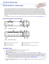
Application Diagrams
Application with “Show Me” Cables
12V
POWER IN
POWER OUT
RS-232
Tx
4
C G T +V
3
C G T +V
2
C G T +V
1
C G T +V
8
C G T +V
7
C G T +V
6
C G T +V
5
C G T +V
G
Tx Rx G
1.0A
MAX
1.0A
MAX
CONTACT IN / TALLY OUT COM
REMOTE
100-240V ~ 50/60 Hz
-- A MAX
1
2
CONFIGURABLE
HDMI
IN1606
HDMI
5
6
HDMI
A
B
3
4
INPUTS OUTPUTS AUDIO INPUTS OUTPUTS REMOTE
L 1
R
L 2
R
L 3
R
L 4
R
L 5
R
+48V
+48V
1 2
L R
VARIABLE
Tx Rx
RS-232
G
LAN
RESET
1
2
MIC/LINE
L 6
R
INPUT
LAN
POWER
12V
500mA
MAX
1 2 3 4
COM 3 IR
3
S G S G
Tx Rx
4
RELAY
3
4
COM1
Tx Rx
RTS CTS
COM 2 IR
1
S G S G
Tx Rx
2
RELAY
1
2
RS-232
RS-232
Ethernet
Ethernet
Flat Panel Display
HDMI Video and
Embedded Audio
Contact Closure and Tally
Contact Closure and Tally
Power
Supply
Extron
CTR 8
Eight Input Contact
Closure to RS-232
Control Module
Extron
IN1606
Scaling Presentation
Switcher
VGA/HDMI “Show Me” Cables
TCP/IP
Network
Extron
IPL 250
IP Link Control
Processor

CTR 8 • Introduction 2
Application with CCR 4BLB
--A MAX
POWER
12V
1
VIDEORGB/R-Y,Y,B-Y HDMI
DSC 301 HD
AUDIO
23
1
RS-232
Tx Rx G
23
INPUTS
OUTPUT
REMOTE
PWR
+ G
INPUTS
1 2 G 3 4 G
OUTPUTS
1 2 G 3 4 G
12V
POWER IN
POWER OUT
RS-232
Tx
4
CGT+V
3
CGT+V
2
CGT+V
1
CGT+V
8
CGT+V
7
CGT+V
6
CGT+V
5
CGT+V
G
Tx Rx G
1.0A
MAX
1.0A
MAX
CONTACT IN / TALLY OUT COM
REMOTE
CGT+V
PUSH PUSH
POWER GUIDEMENU RES 480 480p 720p 1080i 1080p
DIRECTV HD
SELECT
DIRECTV
Extron
DSC 301 HD
Three Input Compact
HDCP-Compliant Video Scaler
RS-232
Power Out
Tally
Contact Closure
Ground
Power Supply
12V 1A
Flat Panel Display
HDMI Video and
Embedded Audio
Extron
CTR 8
Eight Input Contact Closure
to RS-232 Control Module
Power Supply
DVD Player
Laptop
Extron
CCR 4BLB
Four-Button Contact Closure
Remote With Customizable
Backlit Buttons
Cable Box
Contact Closure AAP
Solder Cups
Normally
Closed (NC)
Normally
Open (NO)
Common
Ground (C)
LED (-)
LED (+)
PC
The diagram close‑up below shows how to connect the CCR 4BLB to the CTR 8.
12V
POWER IN
POWER OUT
RS-232
Tx
4
CGT+V
3
CGT+V
2
CGT+V
1
CGT+V
8
CGT+V
7
CGT+V
6
CGT+V
5
CGT+V
G
Tx Rx G
1.0A
MAX
1.0A
MAX
CONTACT IN / TALLY OUT COM
REMOTE
PWR
+ G
INPUTS
1 2 G 3 4 G
OUTPUTS
1 2 G 3 4 G
CTR 8
CCR 4BLB
Tally
Contact Closure
Ground
Application with Individual Contact Closure Switch
12V
POWER IN
POWER OUT
RS-232
Tx
4
CGT+V
3
CGT+V
2
CGT+V
1
CGT+V
8
CGT+V
7
CGT+V
6
CGT+V
5
CGT+V
G
Tx Rx G
1.0A
MAX
1.0A
MAX
CONTACT IN / TALLY OUT COM
REMOTE
Two Contact Closure Switch AAP
PC
Solder Cups
Normally
Closed (NC)
Normally
Open (NO)
Common
Ground (C)
LED (-)
LED (+)
CTR 8
Resistor (R)
NOTE: Determine and select the appropriate
current-limiting resistor, if needed. Some b
utton
switches have the resistor built in.

CTR 8 • Introduction 3
Application with IPLink Control Processor
12V
POWER IN
POWER OUT
RS-232
Tx
4
CGT+V
3
CGT+V
2
CGT+V
1
CGT+V
8
CGT+V
7
CGT+V
6
CGT+V
5
CGT+V
G
Tx Rx G
1.0A
MAX
1.0A
MAX
CONTACT IN / TALLY OUT COM
REMOTE
Extron
CTR 8
Eight Input Contact Closure
to RS-232 Control Module
12V
0.5A
LAN
COM1
COM2
COM1
TX RX TX RX
COM2
Display
Extron
IPL T S2
IP Link Control
Processor
SHARELINK
BLU-RAY
ON/OFF
Extron
CCB 30
Three-Button Contact
Closure Remote
NOTE: To use this application, the CTR 8 must be set to the Advanced operating mode. For
details on operating modes and on this kind of application, see CTR 8 Operating
Modes
on page 7.
Features
• Eight contact closure inputs with tally allow remote switching and selection
status using simple push‑button control.
• COM switcher port sends SIS commands to an Extron switcher for input switching
and muting.
• A/V muting allows the user to mute a switcher output by consecutively pushing the
same input button.
• +5 VDC output on each contact closure input is used to light an LED, indicating
input selection.
• Remote RS-232 port for remote control using Extron Simple Instruction Set (SIS)
commands.
• DC power input with loop-through allows one power supply to power the CTR 8
and an additional Extron device.
• MBU 123 low-profile mount kit included — For installations under tables,
lecterns, desks, or other surfaces. It can also be used to mount products behind flat
panels and other displays.

CTR 8 • Panels and Cabling 4
Panels and
Cabling
This section covers the following:
• Front Panel Features
• Rear Panel Features and Cabling
Front Panel Features
CTR 8
Power LED — Lights green when the unit is receiving power.
Figure 1. CTR 8 Front Panel
Rear Panel Features and Cabling
The following section covers rear panel features and cabling procedures. If mounting is
necessary before connecting cables, see the Mounting section on page 13.
ATTENTION:
• Turn the input and output devices off and unplug their power cords. Verify that the
CTR 8 is disconnected from the power source before proceeding.
• Éteindre tous les appareils d’entrée et de sortie puis retirer les câbles d’alimentation.
Vérifiez que le CTR 8 soit déconnecté de la source d’alimentation avant de procéder.
12V
POWER IN
POWER OUT
RS-232
Tx
4
CGT+V
3
CGT+V
2
CGT+V
1
CGT+V
8
CGT+V
7
CGT+V
6
CGT+V
5
CGT+V
G
Tx Rx G
1.0A
MAX
1.0A
MAX
CONTACT IN / TALLY OUT COM
REMOTE
AA
BB
CC
DD
Figure 2. CTR 8 Rear Panel
A
Power connectors
(see next page)
B
Contact inputs with
tally (see page 6)
C
Remote RS-232 port
(see page 6)
D
COM switcher port
(see page 6)

CTR 8 • Panels and Cabling 5
A
DC power input with loop through (see figure 2) — Wire the external
12 VDC power supply as shown in figure 3 and connect it to the two‑pole
captive screw Power In connector.
SECTION A–A
Ridges
Smooth
Power Supply Output Cord
A
A
3/16”
(5 mm) Max.
Figure 3. Power Connection
Power Out connector — This connector allows power to be looped to
an Extron device that uses +12 VDC voltage. Follow the same pin diagram
above to connect a device to the Power Out connector.
ATTENTION:
• The length of the exposed wires in the stripping process is critical. The ideal length
is 3/16 inches (5 mm). Any longer and the exposed wires may touch, causing a
short circuit between them. Any shorter and the wires can be easily pulled out even
if tightly fastened by the captive screws.
• La longueur des câbles exposés est primordiale lorsque l’on entreprend de les
dénuder. La longueur idéale est de 5mm (3/16inches). S’ils sont un peu plus longs,
les câbles exposés pourraient se toucher et provoquer un court circuit. S’ils sont un
peu plus courts, ils pourraient sortir, même s’ils sont attachés par les vis captives.
• Always use a power supply supplied by or specified by Extron. Use of an
unauthorized power supply voids all regulatory compliance certification and may
cause damage to the supply and the end product.
• Utilisez toujours une source d’alimentation fournie par Extron. L’utilisation d’une
source d’alimentation non autorisée annule toute conformité réglementaire et peut
endommager la source d’alimentation ainsi que l’unité.
• If not provided with a power supply, this product is intended to be supplied by a
power source marked “Class 2” or “LPS” and rated at 12 VDC and a minimum of
1.0 A.
• Si ce produit ne dispose pas de sa propre source d’alimentation électrique, il doit
être alimenté par une source d’alimentation de classe 2 ou LPS et paramétré à 12 V
et 1.0 A minimum.
• Unless otherwise stated, the AC/DC adapters are not suitable for use in air handling
spaces or in wall cavities. The power supply is to be located within the same vicinity
as the Extron AV processing equipment in an ordinary location, Pollution Degree 2,
secured to the equipment rack within the dedicated closet, podium, or desk.
• Sauf mention contraire, les adaptateurs AC/DC ne sont pas appropriés pour une
utilisation dans les espaces d’aération ou dans les cavités murales. La source
d’alimentation doit être située à proximité de l’équipement de traitement audiovisuel
dans un endroit ordinaire, avec un degré2 de pollution, fixé à un équipement de
rack à l’intérieur d’un placard, d’une estrade, ou d’un bureau.
• The installation must always be in accordance with the applicable provisions of
National Electrical Code ANSI/NFPA 70, article 725 and the Canadian Electrical
Code part 1, section 16. The power supply shall not be permanently fixed to
building structure or similar structure.
• Cette installation doit toujours être en accord avec les mesures qui s’applique au
National Electrical Code ANSI/NFPA70, article725, et au Canadian Electrical Code,
partie1, section16. La source d’alimentation ne devra pas être fixée de façon
permanente à une structure de bâtiment ou à une structure similaire.
POWER IN
POWER OUT
1.0A
MAX
1.0A
MAX
POWER IN
POWER OUT
1.0A
MAX
1.0A
MAX

CTR 8 • Panels and Cabling 6
B
Contact closure inputs with tally outputs (see figure 2 on page 4) — Connect
contact closure source devices to these 4‑pole female captive screw connectors. Wire
each connector as shown in figure 4.
NOTES:
• For “Show Me” cables, the ground pin connection is optional.
• Do not connect “Show Me” cables to the +V pin.
CGT+V
Contact (C)
Ground (G)
Tally output (T)
T
ally voltage (+V)
Transmit (Tx)
Receive (Rx)
Ground (G)
Tx Rx
RS-232
G
Transmit (Tx)
Ground (G)
Tx
COM
G
Figure 4. Contact Input Wiring
• C = Contact input pin: Momentary closure of this pin to ground selects the
corresponding number input. Selection is triggered specifically at the moment of
closing, not opening.
• G = Ground pin
• T = Tally output pin: controls the LEDs on push buttons. When an input is
selected, only the tally corresponding to that input is active.
• +V = Tally voltage output pin (optional): provides the +5 VDC supply voltage
needed to illuminate tally LEDs.
C
Remote RS-232 port — Connect the serial port of a control computer to this female
captive screw connector as shown below.
CGT+V
Contact (C)
Ground (G)
Tally output (T)
Tally voltage (+V)
Transmit (Tx)
Receive (Rx)
Ground (G)
Tx Rx
RS-232
G
Transmit (Tx)
Ground (G)
Tx
COM
G
Figure 5. RS-232 Input Wiring
The protocol for the RS‑232 port is 9600 baud, 8 data bits, 1 stop bit, no parity.
D
COM switcher port — Connect an Extron switcher to this female captive screw
connector as shown below. Only connect the Tx and G pins of the CTR 8.
Transmit (Tx)
Ground (G)
Tx
COM
G
RxTx
REMOTE
CTR 8 Switcher
G
Figure 6. COM Input Wiring
The protocol for the COM port is 9600 (default), 19200, 38400, or 57600 baud; 8 data
bits, 1 stop bit, no parity.

CTR 8 • Configuration 7
Configuration
The following features are configured using SIS commands (see the SIS Commands section
on page 10 for information on using SIS commands). This section covers the following topics:
z CTR 8 Operating Modes
z A/V Muting
CTR 8 Operating Modes
The CTR 8 operates in two different modes, which can be set using the Set mode SIS
command on page 12. Each mode has its own set of features and SIS commands (see the
Command and Response Table for SIS Commands on page 12).
• Default mode: In the default operating mode, all CTR 8 contact and tally pins are
tied to one another. Therefore, when a CTR 8 input is selected, all other inputs are
deselected.
• Advanced mode: In this mode, the contact and tally pins are not tied to one another,
meaning that multiple inputs can be selected simultaneously.
This allows a control processor, such as an Extron IP Link, to be connected to the
Remote port of the CTR 8 (see Application with IPLink Control Processor on
page 3). The control processor monitors responses from the CTR 8. When the control
processor detects a change from the CTR 8 unsolicited commands, the control
processor operates as configured.
Other Advanced mode features, which can be set through SIS commands, allow you to:
• Independently control the tally pins. The Set individual ports SIS command (see
page 12) can be used to enable the tally outputs, independent of the state of the
contact input or of other tally ports.
• Select all tally ports with a single SIS command string.
• Monitor (query) contact and tally states. Queries can be made of all contact and
tally pins simultaneously, or of individual contact and tally pins.
A/V Muting
The CTR 8 allows A/V muting for a selected input. This feature allows users to press
the selected input button to mute and unmute the audio and video as needed during a
presentation.
• Press the button once to select an input (Select state)
• Press the same button again to activate A/V mute (De‑select state)
• Press the button once more to return to the Select state, which selects the input and
unmutes the audio and video
NOTE: The A/V mute feature is only triggered by contact closure. SIS input selection (for
example, entering 1! two times) does not trigger the de‑select state.

CTR 8 • Configuration 8
A/V Mute Modes
There are three A/V mute modes, based on the device type (scaler or switcher):
• Mute mode 1: Mutes switcher input by selecting channel 0
• Mute mode 2: Mutes video and audio individually
• Mute mode 3: Mutes video and sync
NOTE: Mute mode 0 is the normal (default) single state operation. A/V mute is not
activated in this mode.
The following is a partial list of Extron switchers for A/V mute modes 1, 2, and 3.
NOTE: Other switchers and scalers are compatible with the mute modes. Contact
Extron Technical Support for assistance with your Extron device.
• Mute mode 1: MLS 608, MPS 602
• Mute mode 2: MLS 608, DSC 301 HD, DVS 605
• Mute mode 3: IN1606, IN1608, DSC 301 HD, DVS 605
A/V mute modes are activated via SIS commands sent to the CTR 8 through the Remote
port. The COM port then sends SIS commands to the switcher. The table below shows the
different commands that the COM port sends for each A/V mute mode.
Button Input
Number
Button State Mute
mode 0
Mute
mode 1
Mute mode
2
Mute
mode 3
1 Select
1! 1! 1! 0B 0Z 1! 0B
1 De‑select
- 0! 1B 1Z 2B
2 Select
2! 2! 2! 0B 0Z 2! 0B
2 De‑select
- 0! 1B 1Z 2B
3 Select
3! 3! 3! 0B 0Z 3! 0B
3 De‑select
- 0! 1B 1Z 2B
4 Select
4! 4! 4! 0B 0Z 4! 0B
4 De‑select
- 0! 1B 1Z 2B
5 Select
5! 5! 5! 0B 0Z 5! 0B
5 De‑select
- 0! 1B 1Z 2B
6 Select
6! 6! 6! 0B 0Z 6! 0B
6 De‑select
- 0! 1B 1Z 2B
7 Select
7! 7! 7! 0B 0Z 7! 0B
7 De‑select
- 0! 1B 1Z 2B
8 Select
8! 8! 8! 0B 0Z 8! 0B
8 De‑select
- 0! 1B 1Z 2B
NOTES:
• A/V mute commands sent from the COM port
to the switcher:
0B = unmute video
1B = mute video (not sync)
2B = mute video and sync
0Z = unmute audio
1Z = mute audio
• A/V mute mode 0 does not have a De‑select state.

CTR 8 • Configuration 9
LED Responses for Video Muting
The CTR 8 allows button LED responses to indicate when video is muted. Button LEDs are
controlled by the Tally Output signal. The CTR 8 offers three different LED modes, which are
set using the A/V Mute Mode SIS command.
• LED Mode 0 = LED of selected input is always on (Default)
• LED Mode 1 = LED of selected input turns Off when muted
• LED Mode 2 = LED of selected input blinks when muted
NOTE: LED mode can be set only when A/V Mute Mode is 1, 2, or 3. If A/V Mute Mode
is 0, LED mode is 0.

CTR 8 • SIS Commands 10
SIS Commands
This section covers the following:
z Using Simple Instruction Set (SIS) Commands
z Symbols Used in this Guide
z Command and Response Table for SIS Commands
Using Simple Instruction Set (SIS) Commands
The CTR 8 is controlled remotely using Extron SIS commands issued from a host computer
running the Extron DataViewer utility or other control system. The host device is connected to the
Remote port on the rear panel of the CTR 8.
The protocol is 9600 baud, 8 data bit, 1 stop bit, and no parity.
Host-to-CTR 8 Communications
SIS commands consist of strings (one or more characters per command field). No special
characters are required to begin or end a command sequence. When the CTR 8 determines that
a command is valid, it executes the command and sends a response to the host device.
Most responses from the CTR 8 end with a carriage return and a line feed (CR/LF =
]), which
signals the end of the response character string.
CTR 8-Initiated Messages
When a local event such as a change in signal status takes place, the CTR 8 sends a message
to the host, indicating the status change. No response is required from the host.
When the CTR 8 is first switched on, it sends the message:
(c)
Copyright 20yy, Extron Electronics, CTR 8, V x.xx, 60-1408-01] where
20yy is the year the currently installed version of the firmware was released, and V x.xx is the
firmware version number.

CTR 8 • SIS Commands 11
Symbols Used in this Guide
When programming in the field, certain characters are more conveniently represented by their
hexadecimal rather than their ASCII values. The table below shows the hexadecimal equivalent of
each ASCII character:
ASCII to Hex Conversion Table
•
Space
Table 1. ASCII to HEX Conversion Table
]
=
carriage return with line feed
}
=
carriage return (no line feed)
•
=
Space
E
=
Escape key
The
X/ values defined in this section are the variables used in the Command Response Table.
X)
=
Input 0‑8
NOTE: For the Advanced Mode commands, only use input numbers
1‑8 (not 0).
X!
=
Set Operating Mode
0 = Default mode
1 = Advanced mode
X@
=
Input selection status
0 = Not Selected
1 = Selected Input 0‑8
X#
=
A/V mute mode
0 = Normal operation, no muting (default)
1 = Channel 0 A/V mute (0!)
2 = Video Mute (1B) and Audio Mute (1Z)
3 = Video and Sync Mute (2B)
X$
=
Mute LED mode
0 = Always on (default)
1 = Off when muted
2 = Blink when muted
X2%
=
Baud rate: 9600, 19200, 38400, 57600 (default = 9600)
NOTE: Unless otherwise indicated, commands are not case‑sensitive.
Error Messages
E10 = Invalid command
E13 = Invalid value (too large)
E14 = Invalid for current configuration/mode

CTR 8 • SIS Commands 12
Command and Response Table for SIS Commands
Command ASCII Command
(host to unit)
Response
(unit to host)
Additional
Description
Set Operating Mode
Set mode
EX!MODE} ModeX!]
Query mode
EMODE} X!]
Default Mode
Select input
X)! Chn•X)] X) = input 0‑8
View last selected input
!
X)]
Query contact closure status
S/s
X@X@X@X@X@X@X@X@]
Least significant input
on far left
Example response:
01000000
]
Contact input 2 is
selected
Unidirectional Serial Data Port
Configure port parameters
Example command:
E2*X2%,n,8,1CP}
E2*19200,n,8,1CP }
Cpn2•CcpX2%,N,8,1]
N = Parity = None
8 = Data bits
1 = Stop bit
View parameters
E2CP} X2%,N,8,1]
Advanced Mode
Contact Ports
Physical contact (open or
close) from ports 1‑8
Sts
X#•X@]
Query individual ports
X)S X@]
Query all ports
S/s
X@X@X@X@X@X@X@X@]
Tally Ports
Set individual ports
EX)*X@TALY} TalyX)*X@]
Query individual ports
EX)TALY} X@]
Set all ports
EX@X@X@X@X@X@X@X@
TALY}
TalyX@X@X@X@X@X@X@X@]
Query all ports
ETALY} X@X@X@X@X@X@X@X@]
Both Modes
A/V Mute Mode
Configure A/V mute mode EX#*X$MUTM} MutmX#*X$]
View A/V mute mode setting
EMUTM} X#*X$]
Other
Information request
I/i
CTR
•8]
Request part number
N/n
60-xxxx-xx
]
View the part number
Query firmware version
Q/q
x.xx
]
Firmware build (2
decimal places)
Query full firmware version
*Q/*q
x.xx.xxxx
]
View the full firmware
Reset all device settings to
factory
EzXXX} Zpx]

CTR 8 • Reference Information 13
Reference
Information
This section covers the following:
z Mounting
z Updating Firmware with Firmware Loader
Mounting
Tabletop Placement
Attach the four provided rubber feet to the bottom of the unit and place it in any convenient
location.
Rack Mounting
UL Guidelines for Rack Mounting
The following Underwriters Laboratories (UL) guidelines are relevant to the safe installation of
these products in a rack:
• Elevated operating ambient temperature — If the unit is installed in a closed or
multi‑unit rack assembly, the operating ambient temperature of the rack environment
may be greater than room ambient temperature. Therefore, install the equipment in an
environment compatible with the maximum ambient temperature
(TMA = +122 °F, +50°C) specified by Extron.
• Reduced air flow — Install the equipment in the rack so that safe operation and
adequate air flow is provided to the unit.
• Mechanical loading — Mount the equipment in the rack so that a hazardous
condition is not achieved due to uneven mechanical loading.
• Circuit overloading — Connect the equipment to the supply circuit and consider the
effect that circuit overloading might have on overcurrent protection and supply wiring.
Consider the equipment nameplate ratings when addressing this concern.
• Reliable earthing (grounding) — Maintain reliable grounding of rack‑mounted
equipment. Pay particular attention to supply connections other than direct
connections.
Rack Mounting Procedure
These units can be mounted an optional rack systems listed on the website (see
www.extron.com). To mount the unit on a rack shelf, follow the instructions provided with
the shelf accessories.

CTR 8 • Reference Information 14
Back of the Rack Mounting Procedure
The CTR 8 can be mounted to the rear of a rack using an optional back of rack mounting kit
(see www.extron.com). The kit allows the product to be vertically mounted to the front or
rear rack supports and face either the front or the rear of the rack. To mount the unit, follow
the instructions provided with the kit.
Under-desk and Furniture Mounting
Mount the unit under a desk or podium, using the included under‑desk mounting kit. Follow
the instructions provided with the kit.
Updating Firmware with Firmware Loader
To upload and update firmware for the CTR 8, download the new firmware to a connected
computer and upload the firmware with the Extron Firmware Loader utility.
Downloading Firmware Loader
Download Firmware Loader as follows:
1. Go to the Extron website, www.extron.com, and click the Download tab (see figure 7,
1
).
Figure 7. Software on the Extron Website
2. Click the Software link (see figure 7,
2
) on the left sidebar menu.
3. Navigate to Firmware Loader (see figure 8,
1
, below).
4. Click the Download link (see figure 8,
2
) on the right that corresponds with the program.
Figure 8. Firmware Loader Download Link
5. Submit all required information to start the download.

CTR 8 • Reference Information 15
Installing Firmware Loader
1. Once Firmware Loader has been downloaded, run the .exe file from the location where
the file was saved. The installation window opens.
2. Follow the instructions on the installation screens to install Firmware Loader on the
computer.
Downloading CTR 8 Firmware
Figure 9. Downloading Firmware from the Extron Website
To obtain the latest firmware version for the CTR 8:
1. On the Extron website, click the Download tab (see figure 9,
1
).
2. Click the Firmware link on the left sidebar menu (
2
).
3. Navigate to CTR 8.
4. Ensure that the available firmware version is a later version than the current one on the
device.
NOTE: The firmware release notes are a PDF file that provides details about the
changes between different firmware versions. The file can be downloaded from
the same page as the firmware.
5. Click the Download link to the right of the desired device.
6. Submit any required information to start the download. Note where the file is saved.
7. Run the executable file (.exe file extension) and follow the on‑screen instructions to
place the firmware file and release notes on the PC. Note where the file is saved.
/