Page is loading ...

User’s Guide
Extron Electronics, USA
1230 South Lewis Street
Anaheim, CA 92805
USA
714.491.1500
Fax 714.491.1517
Extron Electronics, Europe
Beeldschermweg 6C
3821 AH Amersfoort
The Netherlands
+31.33.453.4040
Fax +31.33.453.4050
Extron Electronics, Asia
135 Joo Seng Road, #04-01
PM Industrial Building
Singapore 368363
+65.6383.4400
Fax +65.6383.4664
Extron Electronics, Japan
Daisan DMJ Building 6F
3-9-1 Kudan Minami
Chiyoda-ku, Tokyo 102-0074 Japan
+81.3.3511.7655
Fax +81.3.3511.7656
www.extron.com
© 2002 Extron Electronics. All rights reserved.
68-174-01 Rev. E
Printed in the USA
04 02
IR 301 Infrared Remote Control
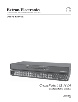
7. Orient the chip with the socket, with the notch toward the front
of the switcher.
IR receiver
IC chip
Main
controller
board
LED
U21
Figure 3 — U21 IR receiver chip socket
8. Carefully align each pin on the chip to its corresponding slot on
the socket.
9. With even pressure, press the chip into the
socket. If you encounter difficulty pressing
the chip into the socket, check to see if any
pins are bent. If so, carefully remove the
chip, straighten the pins, and try again.
10. Apply power to the switcher by connecting
the AC power cord.
11. Check the IR 301’s operation by pointing the remote control
toward the IR Remote window on the front panel of the
switcher. Press the Display Power, Display Mute, RGB Mute,
and Audio Mute buttons on the remote control and verify the
corresponding buttons on the front panel lights.
12. After checking the operation of the switcher, put the top cover
on the switcher and replace the six screws removed in step 4.
13. Reconnect all input and output cables and replace the switcher
in the rack if desired.

IR 301 Infrared Remote Control • Installation and OperationIR 301 Infrared Remote Control • Installation and Operation
Installation and Operation
32
About this User’s Guide
This guide covers the IR 301 infrared (IR) remote control system for
the System 8 Plus and System 10 Plus system switchers.
The IR 301 remote control system consists of:
• An IR 301 hand-held remote control
• An IR receiver IC chip that must be installed in the system
switcher
The remote control can only operate a switcher that is
configured as master, with no switchers slaved to it. Refer
to the associated switcher manual to configure the
switcher.
Aim the hand-held unit at the IR detector on the front of the system
switcher and operate the remote. The maximum operating range of
the IR link is 30 feet. The hand-held remote operates at a carrier
frequency of 38 kHz.
Operation
Pressing the Enter key is not required for these functions.
To select an input using the IR 301 hand-held remote control, aim the
hand-held unit at the IR detector on the system switcher and press
the numeric button for the desired input. The maximum operating
range is 30 feet. For the System 10 switcher, press the 0 key to select
input 10.
The IR 301 also lets the user control the system switcher’s Display
Power, Display Mute, RGB Mute, and Audio Mute functions.
Pressing the keys for these functions on the remote toggles these
functions on and off in the switcher.
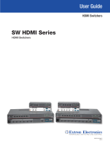
Battery installation
Install two AAA batteries as shown (figure 1).
IR receiver chip installation
Install the IR receiver chip in the System 8/10 Plus System Switcher
as follows:
1. Unplug the switcher.
2. If rack mounted, remove the System 8/10 from the rack.
3. Remove all input and output cables.
4. Place the switcher on a clean work space and remove the three
screws on either side of the switcher (figure 2). Remove the top
cover.
Figure 1 — Battery installation
Figure 2 — Removing the top cover
CAUTION
Use Electrostatic discharge (ESD) precautions by
grounding yourself with an approved wrist strap. Do
not touch the electronic components other than the IC
chip to be installed. Handle the chip by its edges only.
ESD can damage ICs, even if you cannot feel, see, or
hear it.
Do not touch any of the switches. Changed switch
positions can affect the operation of the switcher.
5. Locate vacant IC socket U21 on the main controller board
(figure 3).
6. Using ESD precautions, remove the IC chip from its protective
packaging. Examine the chip to ensure that all pins are straight
and in alignment.
/