Page is loading ...

Unirac Code-Compliant Installation Manual
Unirac welcomes input concerning the accuracy and user-friendliness of this publication. Please write to [email protected].
Pub 15JAN01-1cc
© 2014 - 15
Unirac, Inc.
All rights reserved.
i. Installer’s Responsibilities .................................................................2
Part I. Procedure to Determine the Total Design Wind Load ......................................3
Part II. Procedure to Select Rail Span and Rail Type.............................................10
Part III. Installing SunFrame ...............................................................14
Table of Contents - Code Compliant Installation Manual 809
R

Page
2
Unirac Code-Compliant Installation Manual
SunFrame
R
1411 Broadway Boulevard NE
Albuquerque NM 87102-1545 USA
i. Installer’s Responsibilities
Please review this manual thoroughly before installing your
SunFrame system.
This manual provides (1) supporting documentation for
building permit applications relating to Unirac’s SunFrame
Universal PV Module Mounting system, and (2) planning and
assembly instructions for SunFrame
SunFrame products, when installed in accordance with this
bulletin, will be structurally adequate and will meet the
structural requirements of the IBC 2009, ASCE 7-05 and
California Building Code 2010 (collectively referred to as “the
Code”). Unirac also provides a limited warranty on SunFrame
products (page 24).
SunFrame offers finish choices and low, clean lines that
become as natural a part of a home as a skylight. It delivers the
installation ease you’ve come to expect from Unirac.
Whether for pitched roofs and parking roof structures,
SunFrame was designed from the outset to promote superior
aesthetics. Modules are flush mounted in low, gap-free rows,
and visible components match clear or dark module frames.
The installer is solely responsible for:
• Complying with all applicable local or national building codes,
including any that may supersede this manual;
• Ensuring that Unirac and other products are appropriate for
the particular installation and the installation environment;
• Ensuring that the roof, its rafters, connections, and other
structural support members can support the array under all
code level loading conditions (this total building assembly is
referred to as the building structure);
• Using only Unirac parts and installer-supplied parts as
specified by Unirac (substitution of parts may void the
warranty and invalidate the letters of certification in all Unirac
publications);
• Ensuring that lag screws have adequate pullout strength and
shear capacities as installed;
• Verifying the strength of any alternate mounting used in lieu
of the lag screws;
• Maintaining the waterproof integrity of the roof, including
selection of appropriate flashing;
• Ensuring safe installation of all electrical aspects of the PV
array;
• Ensuring correct and appropriate design parameters are
used in determining the design loading used for design of the
specific installation. Parameters, such as snow loading, wind
speed, exposure and topographic factor should be confirmed
with the local building official or a licensed professional
engineer.

Page
3
SunFrame
Unirac Code-Compliant Installation Manual
R
1411 Broadway Boulevard NE
Albuquerque NM 87102-1545 USA
The procedure to determine Design Wind Load is specified
by the American Society of Civil Engineers and referenced in
the International Building Code 2009. For purposes of this
document, the values, equations and procedures used in this
document reference ASCE 7-05, Minimum Design Loads for
Buildings and Other Structures. Please refer to ASCE 7-05 if
you have any questions about the definitions or procedures
presented in this manual. Unirac uses Method 1, the
Simplified Method, for calculating the Design Wind Load for
pressures on components and cladding in this document.
The method described in this document is valid for flush, no
tilt, SunFrame Series applications on either roofs or walls.
Flush is defined as panels parallel to the surface (or with no
more than 3” difference between ends of assembly) with no
more than 10” space between the roof surface, and the bottom
of the PV panels.
This method is not approved for open structure calculations.
Applications of these procedures is subject to the following
ASCE 7-05 limitations:
1. The building height must be less than 60 feet, h < 60. See
note for determining h in the next section. For installations
on structures greater than 60 feet, contact your local Unirac
Distributor.
2. The building must be enclosed, not an open or partially
enclosed structure, for example a carport.
3. The building is regular shaped with no unusual geometrical
irregularity in spatial form, for example a geodesic dome.
4. The building is not in an extreme geographic location such
as a narrow canyon or steep cliff.
5. The building has a flat or gable roof with a pitch less than 45
degrees or a hip roof with a pitch less than 27 degrees.
6. If your installation does not conform to these requirements
please contact your local Unirac distributor, a local
professional engineer or Unirac
If your installation is outside the United States or does not
meet all of these limitations, consult a local professional
engineer or your local building authority. Consult ASCE 7-05
for more clarification on the use of Method I. Lower design
wind loads may be obtained by applying Method II from ASCE
7-05. Consult with a licensed engineer if you want to use
Method II procedures.
The equation for determining the Design Wind Load for
components and cladding is:
p
net
(psf) = λK
zt
I p
net30
p
net
(psf) = Design Wind Load
λ = adjustment factor for building height and exposure category
K
zt
= Topographic Factor at mean roof height, h (ft)
I = Importance Factor
p
net30
(psf) = net design wind pressure for Exposure B, at height
= 30 ft, I = 1.0
You will also need to know the following information:
Basic Wind Speed = V (mph), the largest 3 second gust of wind in
the last 50 years.
h (ft) = total roof height for flat roof buildings or mean roof
height for pitched roof buildings
Effective Wind Area (sf) = minimum total continuous area of
modules being installed
Roof Zone = the area of the roof you are installing the pv system
according to Figure 2, page 5.
Roof Zone Setback Length = a (ft)
Roof Pitch (degrees)
Exposure Category
Part I. Procedure to Determine the Design Wind Load
[1.1.] Using the Simplified Method - ASCE 7-05:
[1.2.] Procedure to Calculate Total Design Wind:
The procedure for determining the Design Wind Load can be
broken into steps that include looking up several values in
different tables.
Step 1: Determine Basic Wind Speed, V (mph):
Determine the Basic Wind Speed, V (mph) by consulting your
local building department or locating your installation on the
maps in Figure 1, page 4.
Step 2: Determining Effective Wind Area:
Determine the smallest area of continuous modules you will
be installing. This is the smallest area tributary (contributing
load) to a support or to a simple-span of rail. That area is the
Effective Wind Area.

Page
4
Unirac Code-Compliant Installation Manual
SunFrame
R
1411 Broadway Boulevard NE
Albuquerque NM 87102-1545 USA
Miles per hour
(meters per second)
Figure 1. Basic Wind Speeds. Adapted and
applicable to ASCE 7-05. Values are nominal
design 3-second gust wind speeds at 33 feet
above ground for Exposure Category C.
10 3 3 3 3 3 4 4 4 4 4 4 4 5 6 7 8 12 16 20
15 3 3 3 3 3 4 5 6 6 6 6 6 6 6 7 8 12 16 20
20 3 3 3 3 3 4 5 6 7 8 8 8 8 8 8 8 12 16 20
25 3 3 3 3 3 4 5 6 7 8 9 10 10 10 10 10 12 16 20
30 3 3 3 3 3 4 5 6 7 8 9 10 12 12 12 12 12 16 20
35 3 3 3 3 3 4 5 6 7 8 9 10 12.5 14 14 14 14 16 20
40 3 3 3 3 3 4 5 6 7 8 9 10 12.5 15 16 16 16 16 20
45 3 3 3 3 3 4 5 6 7 8 9 10 12.5 15 17.5 18 18 18 20
50 3 3 3 3 3 4 5 6 7 8 9 10 12.5 15 17.5 20 20 20 20
60 3 3 3 3 3 4 5 6 7 8 9 10 12.5 15 17.5 20 24 24 24
Roof Least Horizontal Dimension (ft)
Height (ft)
10 15 20 25 30 40 50 60 70 80 90 100 125 150 175 200 300 400 500
Table 1. Determine Roof/Wall Zone, length (a) according to building width and height
a = 10 percent of the least horizontal dimension or 0.4h, whichever is smaller, but not less than either 4% of the least horizontal
dimension or 3 ft of the building.
Source: ASCE/SEI 7-05, Minimum Design Loads for Buildings and Other Structures, Chapter 6, Figure 6-3, p. 41.
Step 3: Determine Roof/Wall Zone:
The Design Wind Load will vary based on where the
installation is located on a roof. Arrays may be located in more
than one roof zone.
Using Table 1, determine the Roof Zone Setback Length, a (ft),
according to the width and height of the building on which
you are installing the pv system.

Page
5
SunFrame
Unirac Code-Compliant Installation Manual
R
1411 Broadway Boulevard NE
Albuquerque NM 87102-1545 USA
Step 4: Determine Net Design Wind Pressure, p
net30
(psf):
Using the Effective Wind Area (Step 2), Roof Zone Location
(Step 3), and Basic Wind Speed (Step 1), look up the
appropriate Net Design Wind Pressure in Table 2, page 6. Use
the Effective Wind Area value in the table which is smaller than
the value calculated in Step 2. If the installation is located on a
roof overhang, use Table 3, page 7.
Both downforce and uplift pressures must be considered
in overall design. Refer to Section II, Step 1 for applying
downforce and uplift pressures. Positive values are acting
toward the surface. Negative values are acting away from the
surface.
Figure 2. Enclosed buildings, wall and roofs
Flat Roof
Hip Roof (7˚ < θ ≤ 27°)
Gable Roof ( θ ≤ 7°) Gable Roof (7˚ < θ ≤ 45°)
Interior Zones
Roofs - Zone 1/Walls - Zone 4
End Zones
Roofs - Zone 2/Walls - Zone 5
Corner Zones
Roofs - Zone 3
Step 3: Determine Roof Zone (continued):
Using Roof Zone Setback Length, a, determine the roof zone
locations according to your roof type, gable, hip or monoslope.
Determine in which roof zone your pv system is located, Zone
1, 2, or 3 according to Figure 2.
Source: ASCE/SEI 7-05, Minimum Design Loads for Buildings and Other Structures, Chapter 6, p. 41.
h
a
a
a
a
h
a
a
a
a
a TYP
h
a
a
a
a
h
a
a
a
a

Page
6
Unirac Code-Compliant Installation Manual
SunFrame
R
1411 Broadway Boulevard NE
Albuquerque NM 87102-1545 USA
1 10 5.9 -14.6 7.3 -18.0 8.9 -21.8 10.5 -25.9 12.4 -30.4 14.3 -35.3 16.5 -40.5 21.1 -52.0
1 20 5.6 -14.2 6.9 -17.5 8.3 -21.2 9.9 -25.2 11.6 -29.6 13.4 -34.4 15.4 -39.4 19.8 -50.7
1 50 5.1 -13.7 6.3 -16.9 7.6 -20.5 9.0 -24.4 10.6 -28.6 12.3 -33.2 14.1 -38.1 18.1 -48.9
1 100 4.7 -13.3 5.8 -16.5 7.0 -19.9 8.3 -23.7 9.8 -27.8 11.4 -32.3 13.0 -37.0 16.7 -47.6
2 10 5.9 -24.4 7.3 -30.2 8.9 -36.5 10.5 -43.5 12.4 -51.0 14.3 -59.2 16.5 -67.9 21.1 -87.2
2 20 5.6 -21.8 6.9 -27.0 8.3 -32.6 9.9 -38.8 11.6 -45.6 13.4 -52.9 15.4 -60.7 19.8 -78.0
2 50 5.1 -18.4 6.3 -22.7 7.6 -27.5 9.0 -32.7 10.6 -38.4 12.3 -44.5 14.1 -51.1 18.1 -65.7
2 100 4.7 -15.8 5.8 -19.5 7.0 -23.6 8.3 -28.1 9.8 -33.0 11.4 -38.2 13.0 -43.9 16.7 -56.4
3 10 5.9 -36.8 7.3 -45.4 8.9 -55.0 10.5 -65.4 12.4 -76.8 14.3 -89.0 16.5 -102.2 21.1 -131.3
3 20 5.6 -30.5 6.9 -37.6 8.3 -45.5 9.9 -54.2 11.6 -63.6 13.4 -73.8 15.4 -84.7 19.8 -108.7
3 50 5.1 -22.1 6.3 -27.3 7.6 -33.1 9.0 -39.3 10.6 -46.2 12.3 -53.5 14.1 -61.5 18.1 -78.9
3 100 4.7 -15.8 5.8 -19.5 7.0 -23.6 8.3 -28.1 9.8 -33.0 11.4 -38.2 13.0 -43.9 16.7 -56.4
1 10 8.4 -13.3 10.4 -16.5 12.5 -19.9 14.9 -23.7 17.5 -27.8 20.3 -32.3 23.3 -37.0 30.0 -47.6
1 20 7.7 -13.0 9.4 -16.0 11.4 -19.4 13.6 -23.0 16.0 -27.0 18.5 -31.4 21.3 -36.0 27.3 -46.3
1 50 6.7 -12.5 8.2 -15.4 10.0 -18.6 11.9 -22.2 13.9 -26.0 16.1 -30.2 18.5 -34.6 23.8 -44.5
1 100 5.9 -12.1 7.3 -14.9 8.9 -18.1 10.5 -21.5 12.4 -25.2 14.3 -29.3 16.5 -33.6 21.1 -43.2
2 10 8.4 -23.2 10.4 -28.7 12.5 -34.7 14.9 -41.3 17.5 -48.4 20.3 -56.2 23.3 -64.5 30.0 -82.8
2 20 7.7 -21.4 9.4 -26.4 11.4 -31.9 13.6 -38.0 16.0 -44.6 18.5 -51.7 21.3 -59.3 27.3 -76.2
2 50 6.7 -18.9 8.2 -23.3 10.0 -28.2 11.9 -33.6 13.9 -39.4 16.1 -45.7 18.5 -52.5 23.8 -67.4
2 100 5.9 -17.0 7.3 -21.0 8.9 -25.5 10.5 -30.3 12.4 -35.6 14.3 -41.2 16.5 -47.3 21.1 -60.8
3 10 8.4 -34.3 10.4 -42.4 12.5 -51.3 14.9 -61.0 17.5 -71.6 20.3 -83.1 23.3 -95.4 30.0 -122.5
3 20 7.7 -32.1 9.4 -39.6 11.4 -47.9 13.6 -57.1 16.0 -67.0 18.5 -77.7 21.3 -89.2 27.3 -114.5
3 50 6.7 -29.1 8.2 -36.0 10.0 -43.5 11.9 -51.8 13.9 -60.8 16.1 -70.5 18.5 -81.0 23.8 -104.0
3 100 5.9 -26.9 7.3 -33.2 8.9 -40.2 10.5 -47.9 12.4 -56.2 14.3 -65.1 16.5 -74.8 21.1 -96.0
1 10 13.3 -14.6 16.5 -18.0 19.9 -21.8 23.7 -25.9 27.8 -30.4 32.3 -35.3 37.0 -40.5 47.6 -52.0
1 20 13.0 -13.8 16.0 -17.1 19.4 -20.7 23.0 -24.6 27.0 -28.9 31.4 -33.5 36.0 -38.4 46.3 -49.3
1 50 12.5 -12.8 15.4 -15.9 18.6 -19.2 22.2 -22.8 26.0 -26.8 30.2 -31.1 34.6 -35.7 44.5 -45.8
1 100 12.1 -12.1 14.9 -14.9 18.1 -18.1 21.5 -21.5 25.2 -25.2 29.3 -29.3 33.6 -33.6 43.2 -43.2
2 10 13.3 -17.0 16.5 -21.0 19.9 -25.5 23.7 -30.3 27.8 -35.6 32.3 -41.2 37.0 -47.3 47.6 -60.8
2 20 13.0 -16.3 16.0 -20.1 19.4 -24.3 23.0 -29.0 27.0 -34.0 31.4 -39.4 36.0 -45.3 46.3 -58.1
2 50 12.5 -15.3 15.4 -18.9 18.6 -22.9 22.2 -27.2 26.0 -32.0 30.2 -37.1 34.6 -42.5 44.5 -54.6
2 100 12.1 -14.6 14.9 -18.0 18.1 -21.8 21.5 -25.9 25.2 -30.4 29.3 -35.3 33.6 -40.5 43.2 -52.0
3 10 13.3 -17.0 16.5 -21.0 19.9 -25.5 23.7 -30.3 27.8 -35.6 32.3 -41.2 37.0 -47.3 47.6 -60.8
3 20 13.0 -16.3 16.0 -20.1 19.4 -24.3 23.0 -29.0 27.0 -34.0 31.4 -39.4 36.0 -45.3 46.3 -58.1
3 50 12.5 -15.3 15.4 -18.9 18.6 -22.9 22.2 -27.2 26.0 -32.0 30.2 -37.1 34.6 -42.5 44.5 -54.6
3 100 12.1 -14.6 14.9 -18.0 18.1 -21.8 21.5 -25.9 25.2 -30.4 29.3 -35.3 33.6 -40.5 43.2 -52.0
4 10 14.6 -15.8 18.0 -19.5 21.8 -23.6 25.9 -28.1 30.4 -33.0 35.3 -38.2 40.5 -43.9 52.0 -56.4
4 20 13.9 -15.1 17.2 -18.7 20.8 -22.6 24.7 -26.9 29.0 -31.6 33.7 -36.7 38.7 -42.1 49.6 -54.1
4 50 13.0 -14.3 16.1 -17.6 19.5 -21.3 23.2 -25.4 27.2 -29.8 31.6 -34.6 36.2 -39.7 46.6 -51.0
4 100 12.4 -13.6 15.3 -16.8 18.5 -20.4 22.0 -24.2 25.9 -28.4 30.0 -33.0 34.4 -37.8 44.2 -48.6
4 500 10.9 -12.1 13.4 -14.9 16.2 -18.1 19.3 -21.5 22.7 -25.2 26.3 -29.3 30.2 -33.6 38.8 -43.2
5 10 14.6 -19.5 18.0 -24.1 21.8 -29.1 25.9 -34.7 30.4 -40.7 35.3 -47.2 40.5 -54.2 52.0 -69.6
5 20 13.9 -18.2 17.2 -22.5 20.8 -27.2 24.7 -32.4 29.0 -38.0 33.7 -44.0 38.7 -50.5 49.6 -64.9
5 50 13.0 -16.5 16.1 -20.3 19.5 -24.6 23.2 -29.3 27.2 -34.3 31.6 -39.8 36.2 -45.7 46.6 -58.7
5 100 12.4 -15.1 15.3 -18.7 18.5 -22.6 22.0 -26.9 25.9 -31.6 30.0 -36.7 34.4 -42.1 44.2 -54.1
5 500 10.9 -12.1 13.4 -14.9 16.2 -18.1 19.3 -21.5 22.7 -25.2 26.3 -29.3 30.2 -33.6 38.8 -43.2
90 100 110 120 130 140 150 170
Table 2. p
net30
(psf) Roof and Wall
Source: ASCE/SEI 7-05, Minimum Design Loads for Buildings and Other Structures, Chapter 6, Figure 6-3, p. 42-43.
Wall
Basic Wind Speed, V (mph)
Downforce Uplift Downforce Uplift Downforce Uplift Downforce UpliftDownforce Uplift Downforce Uplift Downforce Uplift Downforce Uplift
Effective
Wind Area
(sf)Zone
Roof 0 to 7 degreesRoof 7 to 27 degreesRoof 27 to 45 degrees

Page
7
SunFrame
Unirac Code-Compliant Installation Manual
R
1411 Broadway Boulevard NE
Albuquerque NM 87102-1545 USA
2 10 -21.0 -25.9 -31.4 -37.3 -43.8 -50.8 -58.3 -74.9
2 20 -20.6 -25.5 -30.8 -36.7 -43.0 -49.9 -57.3 -73.6
2 50 -20.1 -24.9 -30.1 -35.8 -42.0 -48.7 -55.9 -71.8
2 100 -19.8 -24.4 -29.5 -35.1 -41.2 -47.8 -54.9 -70.5
3 10 -34.6 -42.7 -51.6 -61.5 -72.1 -83.7 -96.0 -123.4
3 20 -27.1 -33.5 -40.5 -48.3 -56.6 -65.7 -75.4 -96.8
3 50 -17.3 -21.4 -25.9 -30.8 -36.1 -41.9 -48.1 -61.8
3 100 -10.0 -12.2 -14.8 -17.6 -20.6 -23.9 -27.4 -35.2
2 10 -27.2 -33.5 -40.6 -48.3 -56.7 -65.7 -75.5 -96.9
2 20 -27.2 -33.5 -40.6 -48.3 -56.7 -65.7 -75.5 -96.9
2 50 -27.2 -33.5 -40.6 -48.3 -56.7 -65.7 -75.5 -96.9
2 100 -27.2 -33.5 -40.6 -48.3 -56.7 -65.7 -75.5 -96.9
3 10 -45.7 -56.4 -68.3 -81.2 -95.3 -110.6 -126.9 -163.0
3 20 -41.2 -50.9 -61.6 -73.3 -86.0 -99.8 -114.5 -147.1
3 50 -35.3 -43.6 -52.8 -62.8 -73.7 -85.5 -98.1 -126.1
3 100 -30.9 -38.1 -46.1 -54.9 -64.4 -74.7 -85.8 -110.1
2 10 -24.7 -30.5 -36.9 -43.9 -51.5 -59.8 -68.6 -88.1
2 20 -24.0 -29.6 -35.8 -42.6 -50.0 -58.0 -66.5 -85.5
2 50 -23.0 -28.4 -34.3 -40.8 -47.9 -55.6 -63.8 -82.0
2 100 -22.2 -27.4 -33.2 -39.5 -46.4 -53.8 -61.7 -79.3
3 10 -24.7 -30.5 -36.9 -43.9 -51.5 -59.8 -68.6 -88.1
3 20 -24.0 -29.6 -35.8 -42.6 -50.0 -58.0 -66.5 -85.5
3 50 -23.0 -28.4 -34.3 -40.8 -47.9 -55.6 -63.8 -82.0
3 100 -22.2 -27.4 -33.2 -39.5 -46.4 -53.8 -61.7 -79.3
90 100 110 120 130 140 150 170
Table 3. p
net30
(psf) Roof Overhang
Source: ASCE/SEI 7-05, Minimum Design Loads for Buildings and Other Structures, Chapter 6, p. 44.
Roof 27 to 45 degrees Roof 7 to 27 degrees Roof 0 to 7 degrees
Basic Wind Speed, V (mph)
Effective
Wind Area
(sf)Zone
Step 5: Determine the Topographic Factor, K
zt
:
For the purposes of this code compliance document, the
Topographic Factor, K
zt
, is taken as equal to one (1), meaning,
the installation is on level ground (less than 10% slope). If the
installation is not on level ground, please consult ASCE 7-05,
Section 6.5.7 and the local building authority to determine the
Topographic Factor.
Step 6: Determine Exposure Category (B, C, D):
Determine the Exposure Category by using the following
definitions for Surface Roughness Categories.
The ASCE/SEI 7-05* defines wind exposure categories as
follows:
Surface roughneSS b is urban and suburban areas,
wooded areas, or other terrain with numerous closely
spaced obstructions having the size of single family
dwellings.
Surface roughneSS c has open terrain with scat-
tered obstructions having heights generally less than
30 feet. This category includes flat open country,
grasslands, and all water surfaces in hurricane prone
regions.
Surface roughneSS d has flat, unobstructed areas
and water surfaces outside hurricane prone regions.
This category includes smooth mud flats, salt flats, and
unbroken ice.
Also see ASCE 7-05 pages 287-291 for further explanation and
explanatory photographs, and confirm your selection with the
local building authority.

Page
8
Unirac Code-Compliant Installation Manual
SunFrame
R
1411 Broadway Boulevard NE
Albuquerque NM 87102-1545 USA
15 1.00 1.21 1.47
20 1.00 1.29 1.55
25 1.00 1.35 1.61
30 1.00 1.40 1.66
35 1.05 1.45 1.70
40 1.09 1.49 1.74
45 1.12 1.53 1.78
50 1.16 1.56 1.81
55 1.19 1.59 1.84
60 1.22 1.62 1.87
B C D
Table 4. Adjustment Factor (λ) for Roof Height &
Exposure Category
Source: ASCE/SEI 7-05, Minimum Design Loads for Buildings and Other
Structures, Chapter 6, Figure 6-3, p. 44.
Exposure
Mean roof
height (ft)
Step 7: Determine adjustment factor for height and
exposure category, λ:
Using the Exposure Category (Step 6) and the roof height, h
(ft), look up the adjustment factor for height and exposure in
Table 4.
Step 8: Determine the Importance Factor, I:
Determine if the installation is in a hurricane prone region.
Look up the Importance Factor, I, Table 6, page 9, using the
occupancy category description and the hurricane prone
region status.
Step 9: Calculate the Design Wind Load,
p
net
(psf):
Multiply the Net Design Wind Pressure,
p
net30
(psf)(Step 4) by
the adjustment factor for height and exposure, λ (Step 7),the
Topographic Factor, K
zt
(Step 5), and the Importance Factor, I
(Step 8) using the following equation:
p
net
(psf) = λK
zt
I p
net30
p
net
(psf) = Design Wind Load (10 psf minimum)
λ = adjustment factor for height and exposure category (Step 7)
K
zt
= Topographic Factor at mean roof height, h (ft) (Step 5)
I = Importance Factor (Step 8)
p
net30
(psf) = net design wind pressure for Exposure B, at height
= 30, I = 1 (Step 4)
Use Table 5 below to calculate Design Wind Load.
The Design Wind Load will be used in Part II to select the
appropriate SunFrame Series rail, rail span and foot spacing.
Variable Description Symbol Value Unit Step Reference
Building Height h ft
Building, Least Horizontal Dimension ft
Roof Pitch degrees
Exposure Category 6
Basic Wind Speed V mph 1 Figure 1
Effective Roof Area sf
2
Roof Zone Setback Length a ft 3 Table 1
Roof Zone Location 3 Figure 2
Net Design Wind Pressure
p
net30
psf 4 Table 2, 3
Topographic Factor K
zt
x 5
Adjustment factor for height and exposure category λ x 7 Table 4
Importance Factor I x 8 Table 5
Total Design Wind Load
p
net
psf 9
Table 5. Worksheet for Components and Cladding Wind Load Calculation: IBC 2009, ASCE 7-05

Page
9
SunFrame
Unirac Code-Compliant Installation Manual
R
1411 Broadway Boulevard NE
Albuquerque NM 87102-1545 USA
Table 6. Occupancy Category Importance Factor
Source: IBC 2009, Table 1604.5, Occupancy Category of Buildings and other structures, p. 281; ASCE/SEI 7-05, Minimum Design Loads for Buildings and Other
Structures, Table 6-1, p. 77
Category DesicriptionCategory Building Type Examples
Non-Hurricane Prone Regions
and Hurricane Prone Regions
with Basic Wind Speed, V =
85-100 mph, and Alaska
Hurricane Prone Re-
gions with Basic Wind
Speed, V > 100mph
I
II
III
IV
Buildings and other
structures that
represent a low
hazard to human life
in the event of failure,
including, but limited to:
All buildings and other
structures except those
listed in Occupancy
Categories I, III, and IV.
Buildings and other
structures that
represent a substantial
hazard to human life in
the event of a failure,
including, but not limited
to:
Buildings and other
structures designated
as essential facilities,
including, but not limited
to:
Agricultural facilities
Certain Temporary facilities
Minor Storage facilities
Buildings where more than 300 people congregate
Schools with a capacity more than 250
Day Cares with a capacity more than 150
Buildings for colleges with a capacity more than 500
Health Care facilities with a capacity more than 50 or more
resident patients
Jails and Detention Facilities
Power Generating Stations
Water and Sewage Treatment Facilities
Telecommunication Centers
Buildings that manufacture or house hazardous materials
Hospitals and other health care facilities having surgery or
emergency treatment
Fire, rescue, ambulance and police stations
Designated earthquake, hurricane, or other emergency
shelters
Designated emergency preparedness communication, and
operation centers
Power generating stations and other public utility facilities
required in an emergency
Ancillary structures required for operation of Occupancy
Category IV structures
Aviation control towers, air traffic control centers, and
emergency aircraft hangars
Water storage facilities and pump structures required to
maintain water pressure for fire suppression
Buildings and other structures having critical national
defense functions
0.87
1
1.15
1.15
0.77
1
1.15
1.15

Page
10
Unirac Code-Compliant Installation Manual
SunFrame
R
1411 Broadway Boulevard NE
Albuquerque NM 87102-1545 USA
The procedure to determine the Unirac SunFrame series
rail type and rail span uses standard beam calculations and
structural engineering methodology. The beam calculations
are based on a simply supported beam conservatively, ignoring
the reductions allowed for supports of continuous beams over
multiple supports. Please refer to Part I for more information
on beam calculations, equations and assumptions.
In using this document, obtaining correct results is
dependent upon the following:
1. Obtain the Snow Load for your area from your local building
official.
2. Obtain the Design Wind Load, p
net
. See Part I (Procedure
to Determine the Design Wind Load) for more information on
calculating the Design Wind Load.
3. Please Note: The terms rail span and footing spacing
are interchangeable in this document. See Figure 3 for
illustrations.
4. To use Table 8a and Table 8b the Dead Load for your
specific installation must be less than 5 psf, including modules
and Unirac racking systems. If the Dead Load is greater than 5
psf, see your Unirac distributor, a local structural engineer or
contact Unirac.
The following procedure will guide you in selecting a Unirac
rail for a flush mount installation. It will also help determine
the design loading imposed by the Unirac PV Mounting
Assembly that the building structure must be capable of
supporting.
Step 1: Determine the Total Design Load:
The Total Design Load, P (psf) is determined using ASCE 7-05
2.4.1 (ASD Method equations 3,5,6 and 7) by adding the Snow
Load
1
, S (psf), Design Wind Load, p
net
(psf) from Part I, Step
9 and the Dead Load (psf). Both Uplift and Downforce Wind
Loads calculated in Step 9 of Part 2 must be investigated. Use
Table 7 to calculate the Total Design Load for the load cases.
The beam must be sized for uplift, downforce and side loads.
Use the maximum absolute value of the three downforce
cases and and the uplift case to size the beam for uplift and
downforce. Use the side load case to size the beam for side
load. Use the uplift case only for sizing lag bolts pull out
capacities (Part II, Step 6).
P (psf) = 1.0D + 1.0S
1
(downforce case 1)
P (psf) = 1.0D + 1.0
p
net
(downforce case 2)
P (psf) = 1.0D + 0.75S
1
+ 0.75p
net
(downforce case 3)
P (psf) = 0.6D + 1.0
p
net
(uplift)
P (psf) = sin(roof angle)D + sin(roof angle)S
(side)
D = Dead Load (psf)
S = Snow Load (psf)
p
net
= Design Wind Load (psf)
The maximum Dead Load, D (psf), is 5 psf based on market
research and internal data.
1
Snow Load Reduction - The snow load can be reduced according
to Chapter 7 of ASCE 7-05. The reduction is a function of the roof
slope, Exposure Factor, Importance Factor and Thermal Factor.
Please refer to Chapter 7 of ASCE 7-05 for more information.
Part II. Procedure to Select Rail Span and Rail Type
[2.1.] Using Standard Beam Calculations, Structural Engineering Methodology:
Note: Modules must be centered symmetrically on
the rails (+/- 2*), as shown in Figure 3. If this is
not the case, call Unirac for assistance.
B
L
Module length
perpendicular to
rails
Rail Span or Foot Spacing
Figure 3. Rail span and footing
spacing are interchangeable.

Page
11
SunFrame
Unirac Code-Compliant Installation Manual
R
1411 Broadway Boulevard NE
Albuquerque NM 87102-1545 USA
Step 2a: Determine the Distributed Load on the rail
based on uplift and downforce, w (plf):
Determine the Distributed Load, w (plf), by multiplying the
module dimension, B (ft), by the Total Design Load, P (psf). Use
the maximum absolute value of the three downforce cases and
the Uplift Case. We assume each module is supported
by one rail.
w = PB
w = Distributed Load (pounds per linear foot, plf)
B = Module Dimension Perpendicular to Rails (ft., see Figure 3)
P = Total Design Pressure (pounds per square foot, psf)
Step 2b: Determine the Distributed Load on the rail
based on side load, w (plf):
Determine the Distributed Load w (plf), by multiplying the
module width B (ft) by the Total Design Load P (side)
w = PB
w = Distributed Load (pounds per linear foot, plf)
B = Module Dimension Perpendicular to Rails (ft)
P = Total Design Pressure for side load (pounds per square foot, psf)
Step 3: Determine Rail Span/ L-Foot Spacing:
Using the distributed load, w, from Part II, Step 2, look up the
allowable spans, L, for SunFrame.
There are two tables, Table 8a for uplift and downforce and
Table 8b for side load. Look up the allowable span for uplift/
downforce from Table 8a and side load from Table 8b. Span
for the system will be the lower of the 2 appropriate values
from Tables 8a and 8b.
Table 7. ASCE 7 ASD Load Combinations
Note: Table to be filled out or attached for evaluation.
Description Variable Downforce
Case 1
Downforce
Case 2
Downforce
Case 3
Uplift Side Units
Dead Load D 1.0 x D ______
1.0 x S ______
1.0 x D ______
1.0 x P
net
____
1.0 x D _______
0.75 x S _______
0.75 x P
net
____
0.6 x D _______
1.0 x P
net
______
sin(roof angle) x D
__________
sin(roof angle) x S
__________
psf
Snow Load S psf
Design Wind
Load
P
net
psf
Total Design
Load P
P Sum of above two
numbers ______
Sum of above two
numbers ______
Sum of above 3
numbers ______
Sum above two
numbers* ______
Sum above two
numbers ______
psf
Table 8a. L-Foot SunFrame Series Rail Span (uplift and downforce)
20 25 30 40 50 60 80 100 120 140 160 180 200 220240 260280 300
2SFSFSFSFSFSFSFSFSFSFSFSFSFSFSFSFSFSF
2.5SFSFSFSFSFSFSFSFSFSFSFSFSFSFSFSFSFSF
3SFSFSFSFSFSFSFSFSFSFSFSFSFSFSF
3.5SFSFSFSFSFSFSFSFSFSFSFSFSFSF
4SFSFSFSFSFSFSFSFSFSFSFSF
4.5SFSFSFSFSFSFSFSFSFSFSF
5SFSFSFSFSFSFSFSFSFSF
5.5SFSFSFSFSFSFSFSFSFSF
6SFSFSFSFSFSFSFSFSF
6.5SFSFSFSFSFSFSFSF
7SFSFSFSFSFSFSFSF
7.5SFSFSFSFSFSFSFSF
8SFSFSFSFSFSFSF
8.5SFSFSFSFSFSFSF
9SFSFSFSFSFSF
9.5SFSFSFSFSFSF
10 SF SF SF SF SF
10.5 SF SF SF SF
11 SF SF SF SF
11.5 SF SF SF
12 SF SF SF
w = Distributed Load (plf)
Span
(ft)
Table 8a. L-Foot SunFrame Series Rail Span (uplift and downforce)

Page
12
Unirac Code-Compliant Installation Manual
SunFrame
R
1411 Broadway Boulevard NE
Albuquerque NM 87102-1545 USA
Step 4: Select Rail Type:
Selecting a span affects the price of your installation. Longer
spans produce fewer wall or roof penetrations. However,
longer spans create higher point load forces on the building
structure. A point load force is the amount of force
transferred to the building structure at each connection.
It is the installer’s responsibility to verify that the building
structure is strong enough to support the point load
forces.
Step 5: Determine the Downforce Point Load, R (lbs),
at each connection based on rail span:
When designing the Unirac Flush Mount Installation, you
must consider the downforce Point Load, R (lbs) on the roof
structure.
The Downforce, Point Load, R (lbs), is determined by
multiplying the Total Design Load, P (psf) (Step 1) by the Rail
Span, L (ft) (Step 3) and the Module Length Perpendicular to
the Rails, B (ft).
R (lbs) = PLB
R = Point Load (lbs)
P = Total Design Load (psf)
L = Rail Span (ft)
B = Module Length Perpendicular to Rails (ft)
It is the installer’s responsibility to verify that the building
structure is strong enough to support the maximum point
loads calculated according to Step 5.
Table 8b. L-Foot SunFrame Series Rail Span (uplift and downforce)
51015202530354045505560657075808590
2SFSFSFSFSFSFSFSFSFSFSFSFSFSFSFSFSFSF
2.5SFSFSFSFSFSFSFSFSFSFSFSFSFSFSF
3SFSFSFSFSFSFSFSFSFSFSFSF
3.5SFSFSFSFSFSFSFSFSFSF
4SFSFSFSFSFSFSFSFSF
4.5SFSFSFSFSFSFSFSF
5SFSFSFSFSFSFSF
5.5SFSFSFSFSFSF
6SFSFSFSFSFSF
6.5SFSFSFSFSF
7SFSFSFSF
7.5SFSFSFSF
8SFSFSF
8.5SFSFSF
9SFSF
9.5SFSF
10 SF SF
10.5 SF
11 SF
11.5 SF
12 SF
= Distributed Load (plf)
Span
(ft)
Table 8b. L-Foot SunFrame Series Rail Span (side load)
*Note: P
net
uplift will be a negative number

Page
13
SunFrame
Unirac Code-Compliant Installation Manual
R
1411 Broadway Boulevard NE
Albuquerque NM 87102-1545 USA
Total Design Load (downforce) (max of case 1, 2 or 3) P psf Step 1
Module length perpendicular to rails B x ft
Rail Span L x ft Step 4
Downforce Point Load R lbs
Table 9. Downforce Point Load Calculation
Step 6: Determine the Uplift Point Load, R (lbs), at
each connection based on rail span:
You must also consider the Uplift Point Load, R (lbs), to
determine the required lag bolt attachment to the roof
(building) structure.
Total Design Load (uplift) P psf Step 1
Module length perpendicular to rails B x ft
Rail Span L x ft Step 4
Uplift Point Load R lbs
Table 10. Uplift Point Load Calculation
Use Table 11 to select a lag bolt
size and embedment depth to
satisfy your Uplift Point Load
Force, R (lbs), requirements.
It is the installer’s responsibility
to verify that the substructure
and attachment method is strong
enough to support the maximum
point loads calculated according to
Step 5 and Step 6.
Table 11. Lag pull-out (withdrawal) capacities (lbs) in typical roof lumber (ASD)
Lag screw specifications
Specific
5
⁄
16˝ shaft,*
gravity per inch thread depth
Douglas Fir, Larch 0.50 266
Douglas Fir, South 0.46 235
Engelmann Spruce, Lodgepole Pine
(MSR 1650 f & higher) 0.46 235
Hem, Fir, Redwood (close grain) 0.43 212
Hem, Fir (North) 0.46 235
Southern Pine 0.55 307
Spruce, Pine, Fir 0.42 205
Spruce, Pine, Fir
(E of 2 million psi and higher
grades of MSR and MEL) 0.50 266
Sources: American Wood Council, NDS 2005, Table 11.2A, 11.3.2A.
Notes: (1) Thread must be embedded in the side grain of a rafter or other structural member integral with the
building structure.
(2) Lag bolts must be located in the middle third of the structural member.
(3) These values are not valid for wet service.
(4) This table does not include shear capacities. If necessary, contact a local engineer to specifiy lag bolt size
with regard to shear forces.
(5) Install lag bolts with head and washer flush to surface (no gap). Do not over-torque.
(6) Withdrawal design values for lag screw connections shall be multiplied by applicable adjustment factors if
necessary. See Table 10.3.1 in the American Wood Council NDS for Wood Construction.
*Use flat washers with lag screws.
Thread
depth

Page
14
Unirac Code-Compliant Installation Manual
SunFrame
R
1411 Broadway Boulevard NE
Albuquerque NM 87102-1545 USA
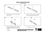
Figure 5. SunFrame threaded slot rail,
cross section, actual size.
1
10
8
9
3
2
1
5
4
4
1
5
12
3
6
2
1
11
7
8
9
Figure 4. SunFrame components.
The Unirac Code-Compliant Installation Instructions supports applications for building permits
for photovoltaic arrays using Unirac PV module mounting systems.
This manual, SunFrame Rail Planning and Assembly, governs installations using the SunFrame
systems.
[3.1.] SunFrame
®
rail components:
Part III. Installing SunFrame

Page
15
SunFrame
Unirac Code-Compliant Installation Manual
R
1411 Broadway Boulevard NE
Albuquerque NM 87102-1545 USA
1. Rail — Supports PV modules. Use one per row of modules
plus one. Shipped in 8- or 16-foot lengths. Aluminum
extrusion, anodized (clear or dark bronze) to match PV
module frame.
2. Cap strip — Secures PV modules to rails and neatly
frames top of array. Lengths equals rail lengths. Cap strips
are sized for specific PV modules. Shipped in 8- or 16-foot
lenghs. Predrilled every 8 inches. Aluminum extrusion,
anodized (clear or dark bronze) to match PV module
frame.
3. Cap strip screw (1/4-20 x 1, Type F thread cut-
ting) — Use to secure each cap strip (and PV modules) to
rail, one per predrilled hole. Use an additional end screw
wherever a predrilled hole does not fall within 4 inches
of the end of any cap strip segment. 18-8 stainless steel,
clear or black to match cap strip.
4. Rail splice — Joins rail sections into single length of rail.
It can form either a rigid or thermal expansion joint. 8
inches long, predrilled. Aluminum extrusion, anodized
(clear or dark bronze) to match PV module frame.
5. Self-drilling screw (No. 10 x 3/4”) — Use 4 per rigid
splice or 2 per expansion joint. Stainless steel.
6. End caps — Use one to neatly close each rail end. UV
resistant black plastic.
7. Truss-head sheet metal screw (No. 8 x 5/8”) — Use 2
per end cap to secure end cap to rail. 18-8 stainless steel;
with black zinc chromate coating to match end caps.
8. L-foot — Use to secure rails either through roofing mate-
rial to rafters, to L-foot adjusting sliders, or to standoffs.
Aluminum extrusion, anodized (clear or dark bronze) to
match PV module frame.
9. L-foot bolt (3/8” x 3/4”) — Use one per L-foot to secure
rail to L-foot. Stainless steel.
10. Flange nut (3/8”) — Use one per L-foot bolt. 304 stainless
steel.
11. L-foot adjusting slider (optional) — Use one beneath
each L-foot or aluminum two-piece standoff, except in
lowest row. Aluminum extrusion. Sliders allow easier
alignment of rails and better snugging of PV modules
between rails. Includes 3/8” x 1-1/4” bolt with flange
nut for attaching L-foot or standoff shaft, and two 5/16”
x 2-1/2” lag bolts with flat washers for securing sliders to
rafters.
12. Two-piece (pictured) — Aluminum extrusion. Includes
3/8” x 3/4” serrated flange bolt with EPDM washer for
attaching L-foot, and two 5/16” x 3-1/2” lag bolts.
Flattop standoff (optional) — Use if L-foot cannot be
secured directly to rafter (with tile or shake roofs, for
example). Use one per L-foot.
One-piece — Service Condition 4 (very severe) zinc-
plated welded steel. Includes 3/8” x 3/4” bolt with lock
washer for attaching L-foot.
Flashings — Use one per standoff. Unirac offers appropri-
ate flashings for both standoff types.
Installer supplied materials:
Lag screw for L-foot — Attaches L-foot or standoff to
rafter. Determine length and diameter based on pull-out
values in Table 3 (page 13). If lag screw head is exposed
to elements, use stainless steel. Under flashings, zinc
plated hardware is adequate. Note: Lag screws are provided
with L-foot adjusting sliders and standoffs.
Waterproof roofing sealant— Use a sealant appropriate
to your roofing material.
Clamps for standing seam metal roof—See “Frequently
Asked Questions . . .” (p. 23).
Stainless steel hardware can seize up, a process
called galling. To significantly reduce its
likelihood, (1) apply lubricant to bolts, preferably
an anti-seize lubricant, available at auto parts
stores, (2) shade hardware prior to installation,
and (3) avoid spinning on nuts at high speed.
See Installation Supplement 910, Galling and Its
Prevention, at www.unirac.com.
1
2
3
4
5
6
7
11
12
8
9
10

Page
16
Unirac Code-Compliant Installation Manual
SunFrame
R
1411 Broadway Boulevard NE
Albuquerque NM 87102-1545 USA
Sample layout, illustrated in Figure 6
Assumptions: 12 modules (60˝ x 36˝), arranged in 4 rows
of 3 modules
4 rows will need 5 shared rails
Array width = 180˝ (60˝ module width x 3 columns)
Array length = 144˝ (36˝ module width x 4 rows)
+ 3˝ (1½˝ end rail width x 2 rails)
+ 2 ¼˝ (¾˝ between-module rail width
x 3 rails)
= 149¼˝
Safe, efficient SunFrame installation involves three principal tasks:
A. Laying out the installation area and planning for material conservation.
B. Installing footings and rails, beginning with the lowest row and moving up the roof.
C. Placing modules and cap strips, beginning with the highest row and moving down the roof.
The following illustrated steps describe the procedure in detail. Before beginning, please note these important considerations.
• Footings must be lagged into structural members. Never attach them to the decking alone, which leaves both the ar-
ray and roof susceptible to severe damage.
• A thermal break is required every 40 feet of continuously connected rail. See Unirac Splices and Expansion Joints
Installation Manual for details.
• There is no UGC (Unirac Grounding Clip) available for SunFrame.
Figure 6. Installation area layout. Note: Module length is not neces-
sarily measured from the edges of the frame. Some frames have lips.
Others are assembled with pan-head screws. All such features must
be included in module length.
1. Laying out the installation area:
Always install SunFrame rails perpendicular to rafters. (These
instructions assume typical rafters that run from the gutter
to the peak of the roof. If this is not the case, contact Unirac.)
Rails are typically mounted horizontally (parallel to the lower
edge of the roof), and must be mounted within 10 degrees of
horizontal.
Leave adequate room to move safely around the array during
installation. During module installation, you will need to slide
one module in each row about a foot beyond the end of the
rails on one side. Using the number of rows and the number
of modules per row in your installation, determine the size of
your array area following Figure 6.
Installing the array:

Page
17
SunFrame
Unirac Code-Compliant Installation Manual
R
1411 Broadway Boulevard NE
Albuquerque NM 87102-1545 USA
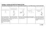
2. Installing the lowest row of L-feet and rail:
In the lowest row, it is not necessary to use L-foot adjust-
ing sliders, even if you plan to use them in subsequent rows.
Install L-feet, in conjunction with proper flashing equipment
and techniques, directly onto low profile roofing material such
as asphalt shingles or sheet metal. (For high profile roofs, such
as tile or shake, use optional standoffs with flashing to raise
L-feet. L-feet must be flush with or above the highest point of
the roof surface.)
L-feet can be placed with the double-slotted side against
the roof surface (as in Fig. 7) or with the single-slotted side
against the roof (which increases air circulation beneath
modules). Module-to-roof dimensions are listed on page 19 for
both arrangements.
If you are using L-foot adjusting sliders, you must use
the short side of the the L-foot against the roof in the
first row. See Figure 9 below.
If you are using both L-foot adjusting sliders and standoffs,
see the upper box on page 18.
Install the first row of L-feet at the lower edge of the instal-
lation area (Fig. 8). Ensure feet are aligned by using a chalk
line. (A SunFrame rail can also be used as a straight edge.)
Position the L-feet with respect to the lower edge of the roof as
illustrated in Figures 7 and 8.
Figure 7. Placement of first L-foot row.
Figure 8. L-Foot
orientation.
Lag
screw
L feet
2¾˝
Lower edge of
installation area
Always lag into slot
nearest the bend in
the L-foot
Roof peak
If the double slotted sides of the L-feet are against the roof, lag through the slot nearest the bend
in the L-foot (Figs. 7 and 8).
Cut the rails to your
array width, being sure
to keep rail slots free
of roofing grit or other
debris. If your instal-
lation requires splices,
assemble them prior to
attaching L-feet (see “Footing and splicing require-
ments,” p. 18, and “Material planning for rails and
cap strips,” p. 20). Slide the
3
/
8
-inch mounting
bolts into the footing slots. If more than one splice
is used on a rail, slide L-foot bolt(s) into the footing
slot(s) of the interior rail segment(s) before splicing.
Loosely attach the rails to the L-feet with the
flange nuts. Ensure that rails are oriented with re-
spect to the L-feet as shown in Figure 9. Align the
ends of the rail to the edge of the installation area.
Ensure that the rail is straight and parallel to the
edge of the roof. Then tighten the lag screws.
Roof peak
Figure 9. L-foot orientation in conjunction with
L-foot adjusting sliders. The sliders include two
utility slots to secure module wiring, combiner
boxes, and other system components.
Utility slot for
1
/
4
″
hexhead bolt
Slot for
3
/
8
″
footing bolt
Utility slot for No. 10 screw

Page
18
Unirac Code-Compliant Installation Manual
SunFrame
R
1411 Broadway Boulevard NE
Albuquerque NM 87102-1545 USA
If the standoff supporting the lowest rail is 1 inch taller than
the standoffs on the footing sliders, place both L-feet in the same
orientation—either both long side up or both short side up.
With standoffs of equal length, orient L-foot to compensate for
height difference.
Footing and splicing requirements
The following criteria are required for sound installations.
While short sections of rail are structurally permissible, they
can usually be avoided by effective planning, which also pro-
motes superior aesthetics. See “Material planning for rails
and cap strips” (p. 20).
The installer is solely responsible for ensuring that the roof and
its structural members can support the array and its live loads.
A thermal break is required every 40 feet of continuously con-
nected rail. See Unirac Splices and Expansion Joints Installa-
tion Manual for details .
1. Footing spacing along the rail (A in illustration above)
is determined by wind loading (see pp. 2–3, especially
step 1).
2. Overhang (B) must be no more than 1/3 the length of
the maximum footing spacing (A). For example, if Span
(A) is 48 inches, Overhang (B) should not exceed 16
inches.
3. Do not locate a splice in the center third of the span
between two adjacent feet.
4. In a spliced length of rail, all sections must be support-
ed by no less than two L-feet.
5. Rail sections longer than half the footing spacing re-
quire no fewer than two L-feet.
Using standoffs with L-foot adjusting sliders
Two-piece aluminum standoffs may be used with footing
sliders, although flashings may not be available to cover the
entire length of the slider. Use the bases of the standoffs
only in the lowest row. In subsequent rows, attach the shaft
of each standoff to the slider using the slider’s
3
/8-inch hex-
head bolt. Note that L-feet are positioned long side up on the
lowest rows and with long side down in subsequent rows—
in the same manner as an installation with no standoffs.
B
A
L-foot
This example assumes a rail seven times the length of the
footing spacing (A). A splice may be located in any of the
shaded areas. If more than one splice is used, be sure the
combination does not violate the following requirements:
Modules should always be fully supported by rails. In other words, modules
should never overhang rails. This is especially critical when supporting the
short side of a non-rectangular module. When a rail supports a pair of non-
rectangular modules by themselves (right), it must be supported by at least
two L-feet. The rail should be at least 14 and no more than 24 inches long,
which will likely require a stringer between rafters to ensure proper footings.
Non-rectangular modules
Rail
Rafters
Stringer

Page
19
SunFrame
Unirac Code-Compliant Installation Manual
R
1411 Broadway Boulevard NE
Albuquerque NM 87102-1545 USA
4. Installing the second rail:
With L-feet only (Fig. 12): Install and align the second rail
in the same manner and orientation as the first rail. After rail
alignment, tighten the rail mounting bolts.
Lay one module in place at one end of the rails, and snug
the upper rail (Fig. 12) toward the lower rail, leaving no gap
between the ends of the modules and either rail. (If pan-head
screw heads represent the true end of the modules, be sure
the screw heads touch the rails on both ends.) Tighten the lag
screw on that end. Slide the module down the rails, snugging
the rails and tightening the remaining lag screws as you go.
With L-foot adjusting sliders: Install rails on first and second
rows of L-feet. Verify spacing by placing a module onto the
rails at several points along the row. Adjust L-foot positions as
needed.
Figure 10. L-foot separation. See the note on module length in the
caption of Figure 3 (p. 10).
3. Laying out and installing the next row of L-feet:
With L-feet only: Position the second row of L-feet in accor-
dance with Figure 10. Ensure that you measure between the
lower bolt hole centers of each row of L-feet. Install the second
row of L-feet in the same manner and orientation as the first
row, but leave the lag screws a half turn loose. Be aware of the
set-up time of your sealant; the L-feet will not be fully tight-
ened until Step. 4.
With L-foot adjusting sliders: Use a chalk line to mark the
position of the slider center holes of the next row. The illustra-
tion below provides spacing guidelines. The length of the
module (A in Fig. 11) includes any protrusions, such as lips or
pan-head screws in its frame.
Attach and seal L-foot adjusting slider: Install lower lag first,
footing bolt next, and upper lag last. Attach an L-foot with its
short side up to each slider.
Module length + ¾˝
(hole to hole)
Figure 12. Position and secure top rail.
Module
Lag screw
(half turn loose)
Lag screw
(tight)
Snug
Roof peak
A = module length
A
A + 2
1
/4
”
A +
3
/4
”
A + 1
3
/16
”
A - 3
1
/4
”
Lowest row of L-feet
(no footing sliders)
Figure 11. If you are using L-foot adjusting sliders, this spacing
between rows places L-feet at the center of their adjustment range.
Align slider
center hole
to chalk line
Align slider
center hole
to chalk line
A
5. Installing remaining L-feet and rails:
Install the L-feet and the rails for the remaining rows, follow-
ing Steps 3 and 4. You may use the same module to space all
the rows. When complete, confirm that:
• All rails are fitted and aligned.
• All footing bolts and lag screws are secure.
• The module used for fitting is resting (but not se-
cured) in the highest row.

Page
20
Unirac Code-Compliant Installation Manual
SunFrame
R
1411 Broadway Boulevard NE
Albuquerque NM 87102-1545 USA
Material planning for rails and cap strips
Preplanning material use for your particular array can prevent
structural or aesthetic problems, particularly those caused by
very short lengths of rail or cap strip. This example illustrates
one approach.
Structural requirements for rails are detailed in “Footing
and splicing requirements” (p.18). Structurally, cap strips
require:
• A screw in every prepunched hole (which occur
every 8 inches, beginning 4 inches from the ends of
the rails).
• One screw 4 inches or less from the each end
of every rail segment. Wherever there is no
prepunched hole within 4 inches of an end of a
segment, drill a
1
/
4
-inch hole 2 inches from the end
of the segment and install a cap strip screw. (In
most cases, you can avoid this situation with good
material planning.)
Structural requirements always take precedence, but usually
good planning can also achieve both material conservation
and superior aesthetics. This example conserves material
and achieves two specific aesthetic goals:
• Cap strip screws must align across the rails.
• End screws must be equidistant from both sides of
the array.
The example assumes an array of three rows, each holding
five modules 41 inches wide. Thus, four 205-inch rail
assemblies and cap strip assemblies need to be cut and
spliced from 192-inch sections of rail and cap strip. The
example illustrates one means of doing so, without violating
structural requirements or aesthetic goals.
Rail segments come from five 192-inch lengths, lettered A
thru E. Rail A, for example, is cut into two 96-inch segments,
with one segment spliced into each of the first two rails.
Similarly, five 192-inch cap strips are designated V through Z.
All cap strip segments are cut at the midpoint between
prepunched screw holes. For each rail, start with the cap
strip segment that crosses the array center line, and position
over the center line so that the appropriate holes are spaced
equally on either side.
Position each cap strip onto its rail and mark its trim point.
Remove and trim before final mounting.
Preliminary footing and splice positions must be
checked against structural requirements in “Footing
and splicing requirements” (p.18). In this example,
the center of the array is offset 2 inches from the center
rafter. This prevents rail splices BD (3rd rail) and CE
(4th rail) from falling too close to the center of the spans
between footings (Requirement 3, p. 18). Because foot-
ings are not visible from ground level, there is negligible
aesthetic loss.
A 96″
B 109″
A 96″
B 83″
C 83″
C 109″
D 122″
E 122″
Array center line
V 112″
W 112″
W 80″
V 80″
X 96″
Y 128″
X 96″
Z 128″
Usable remainder: D, 70″; E, 70″; Y, 64″; Z, 64″
4th cap strip
1st rail
3rd cap strip
2nd rail
2nd cap strip
3rd rail
1st cap strip
4th rail
Trim line (array edge)
Trim line (array edge)
/