Flavor Burst FB 80-08 Operating instructions
- Category
- Baby furniture
- Type
- Operating instructions
This manual is also suitable for

Flavor Burst ®
Soft Serve System
Model FB 80-08
Model FB 80-26
Manufactured by
Flavor Burst Company
499 Commerce Drive
Danville, IN 46122
Phone: (317) 745-2952
Toll Free Number:
(800) 264-3528
Fax: (317) 745-2377
©2007 Flavor Burst Company Printed in March Printed in
All Rights Reserved The United States of America
Warranty
An installation and warranty form is provided with every FB 80 system, located inside the FB 80 unit
with this manual. It is important that the operator carefully review the warranty and installation
documents accompanying the unit before using this system. Any questions or concerns regarding the
warranty should be clarified upon delivery or installation. For more information, contact your local
authorized Flavor Burst ® distributor.
Table of Contents
Introduction…………………………………...……………………….…………………………..….…….………1
Safety Precautions……………………………..………………….………..……..….………………...…....……1
Parts Identification/Function……...……………………………….……..…..……….……………….….……...3
Daily Opening Procedures……..………………………………….…….…..…….……………….…..……….18
Daily Closing Procedures………………………………………….………..……….…………….…………….22
Replacing the Syrup Flavors…………...…………………………………..…….….……………...…………..26
Scheduled Maintenance…………...………………………………………..…….….…………………..….….30
Equipment Setup…………………………………………………………...…..………..….…………...……….44
Keypad Operations…………...…….……………………………………………………………….....……...…58
Troubleshooting Guide………………..……….……………….……………………………..…..….………….64
Directory of Cleaning Procedures……………………………………………...……………..….………….….69
Parts Replacement Schedule………...…………………………….…………………...……...….……………70
Recommended Maintenance Items Replacement Schedule………………..….……………………………71
Alternate Parts and Kits by Freezer Model……………………………………...…..…………………..…….71
Ordering/Service Information…………….…….…………………………………………………………....…..72

INTRODUCTION SAFETY PRECAUTIONS
Congratulations on your purchase of an
FB 80 series flavoring system! As a food and
beverage provider, your customers are your
greatest asset. Your primary concern must be
the health and welfare of your customers. This
manual provides everyday operating guidelines
and procedures. Special functions have been
incorporated into the equipment to provide
simple and effective cleaning and sanitizing of
your unit. We urge you to follow these
instructions carefully and maintain strict sanitary
practices in your daily operating routine.
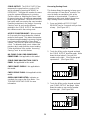
The FB 80 series system is an add-on to a soft
serve freezer designed to inject concentrated
flavorings throughout soft serve product as it is
dispensed. To dispense a flavored product, the
operator first selects the flavor(s) from the
system keypad. The draw-handle must then be
moved into the open position while depressing
the lever on the spigot switch in a smooth
continuous motion to activate the FB 80 system
and dispense flavored product. Returning the
draw-handle to a closed position and releasing
the draw handle switch will stop product flow
and the FB 80 system.
Flavor Burst® syrup is stored within the
equipment cabinet in 1 gallon disposable bags.
Proper syrup injection rate is maintained by
adjusting the flavor level on the system keypad.
Components of the FB 80 system should be
cleaned daily to ensure the highest standard of
sanitation. When your equipment is delivered
or if it has been unused for more than 24 hours,
follow the DAILY OPENING PROCEDURES.
Always follow these safety precautions when
operating the Flavor Burst® system:
DO NOT operate the system without
reading this operator’s manual. Failure to follow
this instruction may result in equipment
damage, poor system performance, health
hazards, or personal injury.
DO NOT operate the system unless it is
properly grounded. Failure to follow this
instruction may result in electrocution.
DO NOT operate the system with larger
fuses than specified on the system data label.
Failure to follow this instruction may result in
electrocution or damage to the machine.
Consult your electrician.
DO NOT put objects or fingers in the
door spout. Failure to follow this instruction may
result in contaminated product or personal
injury from blade contact.
The FB 80 cabinet system must be
placed on a level surface capable of supporting
at least 220 lbs of weight. Failure to comply
may result in personal injury or equipment
damage.
1

DO NOT install the unit in an area where
a water jet could be used, and do not use a
water jet to clean or rinse the system. Failure to
follow these instructions may result in serious
electrical shock.
NOISE LEVEL: Airborne noise emission does
not exceed 70 dB(A) when measured at a
distance of 1.0 meter from the surface of the
machine and at a height of 1.6 meters from the
floor.
NOTE: Operations Manual subject to
change. Contact your local distributor for most
recent updates concerning the FB 80 unit.
2

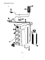
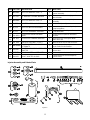
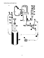
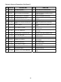
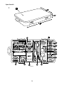
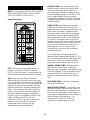
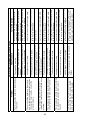
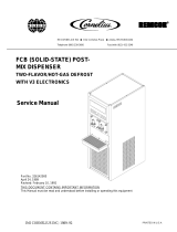
PARTS IDENTIFICATION/FUNCTIONS
General System Overview (See Figure 1)
ITEM PART NO. DESCRIPTION QTY. FUNCTION
1 ELE 430-RE-1 S APIGOT SWITCH ASSEMBLY 1 ctivates Injector Assembly.
2 E K FLE 500 EYPAD ASSEMBLY 1 lavor Burst unit command center.
3 M K MIS 3109 EYPAD BRACKET ASSEMBLY 1 ounts the keypad to the freezer.
4 IN IN InJ 324 JECTOR ASSEMBLY 1 jects syrups into soft serve.
5 M A S
n
IS 3151 CCESSORY HANGING BRACKET 1 tores flavor line and Injector Motor when
ot in use.
6 M S AIS 3026 URFACE RACEWAY (2 FEET) 1 ttaches flavor lines to side of freezer.
7 N C H mps./A ABINET ASSEMBLY 1 ouses flavor trays, electronics, and pu
8 CAB 113 FLAVOR TRAY 8 bags. Houses syrup
9 SYR 943 S
STran
YRUP TUBE ASSEMBLY –
OFT SERVE 8 sports flavors from bag to pump.
10 SAN 740 SANITIZER TANK ASSEMBLY Hous1 es sanitizer cleaning solution.
11 SPR 5800 SPARE PARTS KIT Houses extr s. 1 a spare parts and wear item
12 SYR 941 SYRUP BAG ADAPTER C8 onnects bag fitment to flavor lines.
3

General System Overview
Figure 1
4

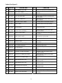
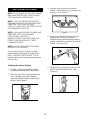
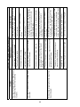
Cabinet (See Figure 2)
ITEM PART NO. DESCRIPTION QTY. FUNCTION
1 N E H/A LECTRONICS SYSTEM 1 ouses microprocessor and electronics.
2 CAB 135R-A RH
b
IGHT SIDE PANEL 1 olds tray support brackets and panel
rackets.
3 C T SAB 145 RAY SUPPORT BRACKET 8 upports flavoring trays.
4 FAS 2024 8 F
s
-32 X 1/4 PAN HEAD 28 astens panel brackets to divider panel,
ecures sides.
5 FAS 2014 8 A
fe
-32 X 1/2" PAN HEAD 25 ttaches top panel, back cover, and
et to cabinet.
6 E S PLE 483 ANITIZER PUMP CABLE 1 rovides power to the sanitizer pumps.
7 E P PLE 496 UMP CABLE 1 rovides power to the syrup pumps.
8 M M PIS 3066 INI BUSHING 1 rotects flush tube.
9 M F C
s
IS 3028 LUSH TUBE ASSEMBLY 1 onnects with flavor line to flush with
anitizer solution.
10 C F P
c
AB 139 RONT DOOR PANEL 1 rovides easy access to syrup bags and
onnectors.
11 CR B
AB 136-A EAR PUMP COVER 1 ack panel to cover pumps.
12 F 3/16" X 3/16" BARB TUBE CONNECT SIX 1023 1 plices together flush tubes.
13 CAB 134 DIVIDER PANEL Hold
fl
1 s tray support brackets and divides
avor trays.
14 CAB 144R RIGHT PANEL BRACKET 3 H port rails. olds tray sup
15 CAB 144L L HEFT PANEL BRACKET 3 olds tray support rails.
16 CAB 143 L P nt panel
la
ATCH BRACKET 1 rovides latching tab for fro
tch.
17 F F L LATCH LAS 2001 RONT DOOR PANE 1 atches front door to cabinet front.
18 SYR 927 INTERNAL 9-TUBE ASSEMBLY T rts syrup from bags to flavor
9
1 ranspo
-Tube Assembly.
19 SAN 748 PERISTALTIC Pumps
a
SANITIZER PUMP 1 sanitizer solution to flush tube
nd sanitizer line.
20 SYR 307 PERISTALTIC SYRUP PUMP P
li
8 umps syrup from flavor bags into flavor
nes.
21 CAB 155L PUMP MOUNTING STRI S
b
P 1 upport for syrup trays and spacing
etween panels.
22 CAB 155R PUMP MOUNTING STRI Support for
b
P 1 syrup trays and spacing
etween panels.
23 FAS 2037 TAPPED NYLON SPACE 12 S
s
R ecures screw to center panel, and
upport for trays.
24 32 STANDARD NYLON SPACERS 12 PFAS 20 rovides extra support for flavor trays.
25 FAS 2034 8 A divider panel. -32 X 3/4" MACHINE SCREW 12 ttaches bushings to
26 MIS 3067 O S
A
PEN/CLOSED BUSHING 1 train relief for internal 9-Tube
ssembly.
5

ITEM PART NO. DESCRIPTION QTY. FUNCTION
27 FIX 1033 1/4" X 1/4" BLKHD (PUSH-TO-
CONNECT) 1 Connects Sanitizer Tank tube to the
unit.
28 TUB 803 TUBING-PER FOOT 1 Transports sanitizer solution from tank
to pump.
29 CAB 133 BASE PANEL 1 Attaches the bottom of the inner and
side panels.
30 RUB 618 RUBBER BUMPER WITH WASHER 6 Provides spacing between cabinet base
and table.
31 FAS 2035 8-32 NUTS - EXT. LOCK WASHER 6 Attaches to screw and holds rubber
bumper in place.
32 MIS 3074 SHORTY PLUG #1672 6 Covers screw hole in rubber bumper.
33 FAS 2040 6-32 X 1/4" TAPPING SCREW 24 Secures tray support bracket to side
panels.
34 CAB 135L-A LEFT SIDE PANEL 1 Holds tray support brackets and panel
brackets.
35 SYR 943 SYRUP TUBE ASSEMBLY –
SOFT SERVE 8 Transports the flavoring from the syrup
bag to the syrup pump.
Cabinet
Figure 2
6

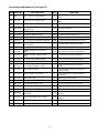
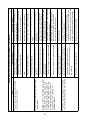
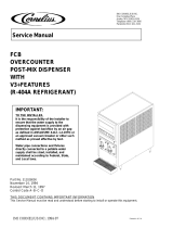
Injector Assembly and Related Parts (See Figure 3)
ITEM PART NO. QTY.
DESCRIPTION FUNCTION
1 ADPT 101A S O-RINGS
- 1 At s Injector Asmb. to most Taylor
fre
POUT ADAPTER WITH
STANDARD tache
ezers & some Crown Series models.
1A RUB 642 ADAPTER O-RING C
fr
1 reates tension to secure Adapter to
eezer door.
1B RUB 640 FLAT ADAPTER GASKET 1 Provides sealed cavity inside Adapter.
1C ADPT 101 SPOUT ADA A ctor Asmb. to freezer door. PTER 1 ttaches Inje
1D RUB 632 S C
In
POUT ADAPTER O-RING 1 reates tension to
jector Head. secure Adapter to
2 IN IN C
p
J 322 JECTOR HEAD ASSEMBLY 1 onnects flavor line to inject syrups into
roduct.
2A RSYRUP PORT O-RI P
UB 652-RSS NG 1 rovides sealed cavity inside syrup port.
2B RUB 651 INJECTO 2-020 P ealed cavity. R HEAD O-RING 1 rovides a s
3 IN G GE ASSEMBLY R
d
J 321 EAR CARTRID 1 otates product for even syrup
istribution.
4 SYR 932 6' 9-TUBE ASSEMBLY 1 Supplies syrup to Injector Head from
pumps.
4A FAS 2051 ROLLED FLANGE EYELET 18 Provides tension in syrup line to affix to
line coupler.
4B ROT 510 LINE COUPLER 2 Holds flavor lines in place.
4C RUB 610 BAG CONNECTOR O-RINGS 1 Provides extra tension between tube
connectors.
4D ROT 515-A 9-TUBE ASSEMBLY. WAVE SPRING 1 Provides tension between tube
connectors.
4E INJ 116 LINE COUPLER NUT - BLACK 1 Attaches flavor tubes to Manifold.
4F SYR 901 6' 9-TUBE ASSEMBLY TUBES 9 Transports syrup from pump to Injector
Head.
4G ROT 511 LINE COUPLER NUT 1 Connects flavor lines to the internal
9-Tube Assembly.
4H RUB 602 9-POS TUBE CONN. GASKET 1 Provides sealed cavity.
5 INJ 117 TUBE CONNECTOR BODY -BLACK 1 Secures Syrup Line Manifold to flavor
lines.
6 MIS 3142 FLAVOR LINE DUST CAP - FB 80 1 Covers Manifold when not
connected.
7 INJ 201 SYRUP MANIFOLD - BLACK 1 Connects flavor line to Injector Head.
8 RUB 601 9-POS DUCKBILL CHECK VALVE 1 Provides sealed cavity and prevents
syrup leakage.
9 MIS 3143 INJECTOR SUSPENSION BRACKET 1 Secures Injector Asmb. to freezer door.
9A FAS 2107 INJECTOR BRACKET KNOB 1 Tightens positioning of hanging bracket.
9B MIS 3144 NYLON SHOULDER WASHER 1 Allows free horizontal movement for
bracket.
7

ITEM PART NO. DESCRIPTION QTY. FUNCTION
9C MIS 3143-A INJ 1 Attaches to free to hang
ECTOR BRACKET PART A zer door bolts
Injector Assembly.
9D ROT 535 IN PRING WASHER 1 b
J. BRACKET S Allows space between hanging and
ase brackets.
9E MIS 3143-B INJ S
A
ECTOR BRACKET PART B 1 ecures bracke
ssembly. t assembly to Injector
10 IN IN PJ 323 JECTOR ASMB. / NO HEAD 1 owers the Injector System.
10A INJ 330 IN SSEMBLY P
syrup into product.
JECTOR MOTOR A 1 owers the Injector Assembly to inject
10B IN IN BLY G
s .
J 331 JECTOR GEARBOX ASSEM 1 ears turn Gear Cartridge to allow even
yrup distribution
10C FAS 2023 ACCESSORY MOUNTING BRKT
KS
G
NOB 1 ecures base Suspension Bracket to
earbox.
11 MIS 3151 ACCESSORY HANGING BRACKET Stores flavor line and Injector Motor
w
1 hen not in use.
12 M S AIS 3026 URFACE RACEWAY (2 FEET) 1 ttaches flavor lines to side of freezer.
13 ADPT 8750-A SPOUT ADA
AA t
T
PTER W/ O-RINGS –
LTERNATE 1 ttaches Injector Assembly to mos
eries freezers. aylor Crown S
13A RADAPTER O-RING FOR ALTERNATE
AC
fr
UB 645 DAPTER 1 reates tension between Adapter and
or. eezer do
13B ADPT 8750 SPOUT ADAPTER - ALTERNATE 1 Attaches Injector Asmb. to freezer door.
13C RUB 632 S C
In
POUT ADAPTER O-RING 1 reates tensio
jector Head. n to secure Adapter to
Injector Assembly
and Related Parts
Figure 3
8

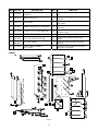
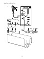
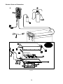
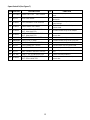
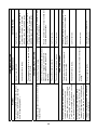
Syrup Pump and Related Parts (See Figure 4)
ITEM PART NO. DESCRIPTION QTY.
FUNCTION
1 N/A SOFT SERVE SYRUP PUMP 8 P vor bags to flavor
li umps syrup from fla
nes.
1A SYR 307 PERISTALTIC SYRUP PUMP 1 ea. P flavor bags to flavor
li umps syrup from
nes.
1B TUB 806 1/8” SYRUP PUMP REPL TUBE 1 ea. T rup through pump. ransports sy
1C FAS 2066 S
W1 ea. Secu
YRUP PUMP TUBE
ASHER-1/4 res pump tube.
1D FAS 2067 SYRUP PUM 1 ea. P rom slipping. P CLAMP-HOSE-1/4" revents pump tube f
1E FAS 2051 R 1 ea. COLLED FLANGE EYELET reates tension for tighter fit.
1F FIX 1036 1 1 ea. C/4" TO 1/4" OD UNION ELBOW onnects syrup in tube to pump.
1G FIX 1035 1/4 TO 3/16 OD REDUCING UNION 1 ea. C rup pump to flavor line out. onnects sy
2 SS
SOFT SERVE T
YR 943 YRUP TUBE ASSEMBLY – 8 ransports flavor from bag to pump.
2A F C 1 ea. CIX 1049 OUPLING-1/8"NPT FB80 onnects flavor line to flavor bag.
2B FIX 1047 E
F1 ea. C
LBOW-BARBED TUBE PORT
B80 onnects flavor in tube to bag fitment.
2C T PE 1 ea. CUB 811 TUBE-SILICONE .188X.375
FB80 onnects barb fitment to tube port.
2D FIX 1048 FITTING-1/4 1 ea. ConX1/4 BARB FB80 nects syrup tube to silicone tube.
2E SYR 902 FLAVOR-IN 1 ea. CarrieTUBE s syrup from syrup bag to pump.
3 SYR 901 6' 9-T B
Hea
UBE ASSEMBLY TUBE 9 rings syrup from
d. pump to Injector
4 ROT 511 LINE COUPLER NUT 1 Connects flavor lines to the internal 9-
Tube Assembly.
5 ROT 512 TUBE CONNECTOR BODY 1 flavor lines.
Connects internal 9-Tube Assembly to
6 ROT 510 LINE COUPLER 1 Holds flavor lines in place.
7 FAS 2051 ROLLED FLANGE EYELET 9 Secures flavor lines to line coupler.
8 MIS 3023 FLAVOR LINE DUST CAP 1 Cover to protect end of flavor lines.
9 SYR 941 SYRUP BAG ADAPTER 8 Connects bag fitment to flavor lines.
9A SYR 940 SYRUP BAG ADAPTER CAP 1 ea. Attaches to flavor bag fitment.
9B SYR 939-A SYRUP BAG ADAPTER VALVE
ASSEMBLY 1 ea. Transports syrup to quick connect
fitment.
9C RUB 632 SYRUP BAG ADAPTER O-RING 1 ea. Provides sealed cavity for Syrup Bag
Adapter.
10 CAB 113 FLAVORING TRAY 8 Houses syrup bags.
11 ELE 496 PUMP CABLE 1 Supplies power to the pumps.
9

Syrup Pump and Related Parts
Figure 4
10

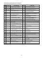
Sanitizer Pump and Related Parts (See Figure 5)
ITEM PART
NO. DESCRIPTION QTY. FUNCTION
1 SAN 748 SANITIZER PUMP ASSEMBLY 1 Supplies sanitizer to flush tube.
2 TUB 807 SANITIZER TUBE REPLACEMENT 1 Transports sanitizer through pump.
3 MIS 3023 DUST CAP 1 Cover to protect end of flavor lines.
4 FAS 2051 ROLLED FLANGE EYELET 1 Creates tension for tighter fit 1 per
pump, 9 per tube assembly.
5 ROT 510 LINE COUPLER 1 Holds flavor lines in place.
6 ROT 512 TUBE CONNECTOR BODY 1 Connects internal 9-Tube Assembly to
flavor lines.
7 ROT 511 LINE COUPLER NUT 1 Connects flavor lines to the internal
9-Tube Assembly.
8 SYR 901 6' 9-TUBE ASSEMBLY TUBES 9 Transports syrup and sanitizer from
pumps to Injector Assembly.
9 FIX 1035 1/4 TO 3/16 OD REDUCING UNION 1 Connects elbow to sanitizer line.
10 n. FIX 1042 TUBE-TO-TUBE ELBOW 1 Connects pump tube to reducing unio
11 apter.SYR 931 CLEAR TUBING 1 Transports sanitizer to Pump Flush Ad
12 FIX 1043 1/4" IDX1/8 90 DG BARB FITTING 1 Connects sanitizer line to sanitizer
pump.
13 FIX 1017 1/8" FEMALE TEE 1 Connects fitments to Sanitizer Tank,
flush line and pump.
14 h
FIX 1034 3/16" ID BARB X 1/8" NPT ELBOW 1 Connects sanitizer line to Pump Flus
Adapter.
15 r
FIX 1044 1/4" TUBE X 1/8" NPT 1 Connects sanitizer line to flush adapte
and pump lines.
16
TUB 803 .17 x 1/4 LDPE TUBING-PER FOOT 1 Transports sanitizer solution from tank
to sanitizer pump.
17 FIX 1036 1/4" TO 1/4" OD UNION ELBOW 1 Connects sanitizer tube to supply tube.
18 SAN 715 SUPPLY TUBE CAP 1 Fastens grommet securely to tank.
19 als
RUB 615 FEEDER TUBE RUBBER GROMMET 1 Holds sanitizer tube in place and se
tank hole.
20 k. SYR 902 SANITIZER SUPPLY TUBING 1 Supplies sanitizer from Sanitizer Tan
21 re
SAN 734 HAND PUMP ASSEMBLY-FLUTED
TANK 1 Seals Sanitizer Tank and adds pressu
when needed.
22 SAN 701 SANITIZER TANK 1 Holds sanitizer solution.
23 MIS 3028 FLUSH TUBE ASSEMBLY 1 Connects with flavor line to flush with
sanitizer solution.
24 FIX 1023 3/16" X 3/16" BARB TUBE CONNECT 1 Splices together flush tubes.
11

Sanitizer Pump and Related Parts
Figure 5
12

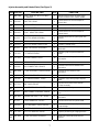
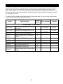
Electronic Parts and Connections (See Figure 6)
ITEM PART NO. DESCRIPTION QTY. FUNCTION
1 ELE 500 KEYPAD ASSEMBLY 1 Flavor Burst unit command center.
2 ELE 430-RE-1 SPIGOT SWITCH ASSEMBLY 1 Activates Injector Assembly.
3 INJ 330 INJECTOR MOTOR ASSEMBLY 1 Powers the Injector Assembly to inject
syrup into product.
4 MIS 3109 KEYPAD BRACKET ASSEMBLY 1 Mounts the keypad to the freezer.
4A MIS 3080 KEYPAD MOUNTING PLATE 1 ea. Attaches to freezer to mount keypad
bracket.
4B MIS 3103 KEYPAD MOUNTING BRACKET 1 ea. Holds keypad in place.
4C FAS 2023 ACCESSORY MOUNTING BRACKET
KNOB 2 ea. Fastens keypad bracket to mounting
plate.
5 ELE 434 POWER CABLE 1 Supplies the electronics board with
power.
6 CAB 137-A ELECTRONICS COVER 1 Protects and covers the electronics
microprocessor.
7
FAS 2014 8-32 X 1/2" PAN HEAD 15 Secures cover panel to base and ground
wire to nut.
8 MIS 3150 FLAVOR BURST LOGO DECALS 1 Displays Flavor Burst trademark logo.
9 FAS 2024 8-32 X 1/4 PAN HEAD 5 Secures microprocessor and power
module to base.
10 ELE 485 120V POWER ENTRANCE MODULE 1 Power source inlet.
11 CAB 156 CONNECTOR SHIELD 1 Protects power cables from liquids;
splash guard.
12 ELE 501 MICROPROCESSOR 1 Main power supply.
13 FAS 2081 STEEL CABLE CLAMPS 2 Strain relief to prevent chords from
being detached.
14 CAB 138-A ELECTRONICS BASE PANEL 1 Secures microprocessor.
15 N/A GROUNDING WIRE 1 Grounds electricity.
16 FAS 2035 8-32 NUTS - EXT. LOCK WASHER 1 Secures ground wire to screw and
panel.
13

Electronic Parts and Connections
Figure 6
14

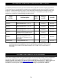
Spare Parts Kit (See Figure 7)
ITEM PART NO. DESCRIPTION QTY. FUNCTION
1 SPR 5800 SPARE PARTS KIT – SOFT SERVE 1 Houses extra spare parts and wear
items.
2 INJ 321 GEAR CARTRIDGE 1 Rotates product for even syrup
distribution.
3 RUB 601 9-POS DUCKBILL CHECK VALVE 1 Provides sealed cavity and prevents
syrup leakage.
4 RUB 632 LOWER ADAPTER O-RING 1 Creates tension to secure Adapter to
Injector Head.
5 RUB 640 FLAT ADAPTER GASKET FOR
ADPT 101A ADAPTER 1 Provides sealed cavity inside Adapter.
6 RUB 642 UPPER ADAPTER O-RING FOR
ADPT 101A ADAPTER 1 Creates tension to secure Adapter to
freezer door.
7 RUB 602 9-POS TUBE CONN. GASKET 1 Provides sealed cavity.
8 rt.
RUB 652-RSS SYRUP PORT O-RING 1 Provides sealed cavity inside syrup po
9 RUB 651 INJECTOR HEAD O-RING 2-020 1 Provides a sealed cavity.
10 INJ 201 SYRUP MANIFOLD - BLACK 1 Connects flavor line to Injector Head.
11 ELE 430-RE-1 SPIGOT SWITCH 1 Activates Injector Assembly.
12 INJ 117 TUBE CONNECTOR BODY -BLACK 1 Secures Syrup Line Manifold to flavor
lines.
13 ELE 444 1 AMP, 1 1/4" SLOW BLOW FUSE 2 System overload protection.
14 RUB 645 UPPER ADAPTER O-RING FOR
ADPT 8750-A ADAPTER 1 Creates tension to secure Adapter to
freezer door.
15

Spare Parts Kit
Figure 7
16

17

18
DAILY OPENING PROCEDURES
NOTE: YOUR HANDS SHOULD BE CLEANED
AND SANITIZED BEFORE YOU PERFORM
THE FOLLOWING PROCEDURES.
NOTE: THE FOLLOWING PROCEDURES
REQUIRE APPROVED, SERVICEABLE AND
SANITIZED TOOLS AND BRUSHES.
CONTACT YOUR LOCAL DISTRIBUTOR FOR
RECOMMENDED SUPPLIES.
NOTE: USE AN APPROVED CLEANER AND
SANITIZER FOR THE FOLLOWING
PROCEDURES. REFER TO
MANUFACTURER’S INSTRUCTIONS FOR
PROPER PREPARATIONS OF THESE
CLEANING AGENTS.
NOTE: INSPECT ALL WEAR ITEMS AND
REPLACE IF NECESSARY.
Ensure that the Injector System has been
disassembled and cleaned according to the
DAILY CLOSING PROCEDURES. This is
typically performed at the close of the previous
business day.
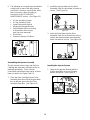
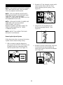
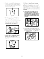
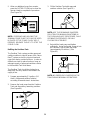
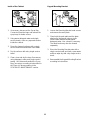
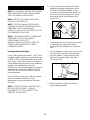
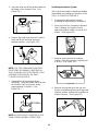
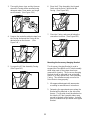
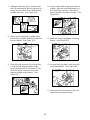
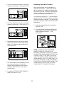
Sanitizing the Injector System
1. Prepare an approved sanitizer solution
according to manufacturer’s instructions.
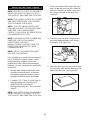
2. Place the Gear Box, Suspension Bracket,
Gear Cartridge, and Injector Head in
approved sanitizer solution and soak for 1
minute. (See Figure 8.)
Figure 8
3. Remove each part from the sanitizer
solution. Place the items on a sanitary tray
to air dry. (See Figure 9.)
Figure 9
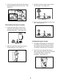
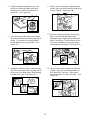
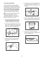
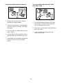
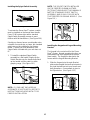
4. Remove the Manifold cap and set it on a
sanitary tray. Spray the Syrup Line
Manifold opening with approved sanitizer
solution and allow it to sanitize for at least 1
minute. (See Figure 10.)
Figure 10
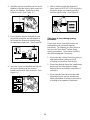
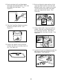
5. Hang the 9-Tube assembly on the 9-Tube
and Drive Motor Bracket to dry. (See
Figure 11.)
Figure 11

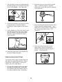
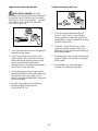
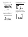
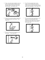
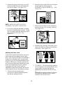
6. The following do not need to be sanitized on
a d g
procedures.
binet
aily basis as part of the daily openin
However, inspect these areas
and if necessary, clean according to
instructions in the SCHEDULED
MAINTENANCE section: (See Figure 12.)
• 9-Tube Assembly Coupler
• 9-Tube Assembly Tubes
• Spigot Switch and Bracket
• Keypad and Keypad Bracket
• Spout Adapter (clean according
to instructions when freezer
door has been removed)
• Drive Motor
• Exposed surfaces of Ca
Figure 12
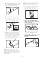
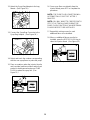
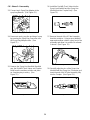
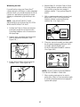
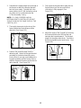
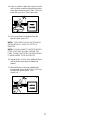
Assembling the Injector Assembly
the Gear
cc
1.
the Drive
he two Injector Head o-rings andT
Cartridge are wear items and will need to be
replaced periodically. Check for wear
asionally and always keep spares of theseo
items on hand in the Spare Parts Kit.
Place the Gear Cartridge into the Drive
Assembly Gear Box so that the gear teeth
line up with the gear inside
Assembly Gear Box. (See Figure 13.)
Figure 13
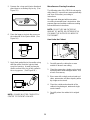
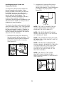
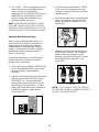
2. Install the Injector Head onto the Drive
ter to Assembly Gear Box and rotate off-cen
secure. (See Figure 14.)
Figure 14
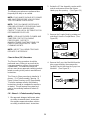
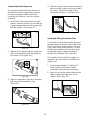
. Insert the Drive Motor into the Drive
e the .)
3Assembly Gear Box so that all four locking
screws are seated properly and rotat
motor clockwise to secure. (See Figure 15
Figure 15
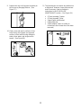
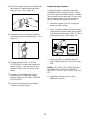
stalling the Injec
e Figure 16.)
In tor System
1. Hang the Suspension Bracket with the
Injector Assembly on one of the lower
freezer door posts. (Se
Figure 16
19
Page is loading ...
Page is loading ...
Page is loading ...
Page is loading ...
Page is loading ...
Page is loading ...
Page is loading ...
Page is loading ...
Page is loading ...
Page is loading ...
Page is loading ...
Page is loading ...
Page is loading ...
Page is loading ...
Page is loading ...
Page is loading ...
Page is loading ...
Page is loading ...
Page is loading ...
Page is loading ...
Page is loading ...
Page is loading ...
Page is loading ...
Page is loading ...
Page is loading ...
Page is loading ...
Page is loading ...
Page is loading ...
Page is loading ...
Page is loading ...
Page is loading ...
Page is loading ...
Page is loading ...
Page is loading ...
Page is loading ...
Page is loading ...
Page is loading ...
Page is loading ...
Page is loading ...
Page is loading ...
Page is loading ...
Page is loading ...
Page is loading ...
Page is loading ...
Page is loading ...
Page is loading ...
Page is loading ...
Page is loading ...
Page is loading ...
Page is loading ...
Page is loading ...
Page is loading ...
Page is loading ...
-
 1
1
-
 2
2
-
 3
3
-
 4
4
-
 5
5
-
 6
6
-
 7
7
-
 8
8
-
 9
9
-
 10
10
-
 11
11
-
 12
12
-
 13
13
-
 14
14
-
 15
15
-
 16
16
-
 17
17
-
 18
18
-
 19
19
-
 20
20
-
 21
21
-
 22
22
-
 23
23
-
 24
24
-
 25
25
-
 26
26
-
 27
27
-
 28
28
-
 29
29
-
 30
30
-
 31
31
-
 32
32
-
 33
33
-
 34
34
-
 35
35
-
 36
36
-
 37
37
-
 38
38
-
 39
39
-
 40
40
-
 41
41
-
 42
42
-
 43
43
-
 44
44
-
 45
45
-
 46
46
-
 47
47
-
 48
48
-
 49
49
-
 50
50
-
 51
51
-
 52
52
-
 53
53
-
 54
54
-
 55
55
-
 56
56
-
 57
57
-
 58
58
-
 59
59
-
 60
60
-
 61
61
-
 62
62
-
 63
63
-
 64
64
-
 65
65
-
 66
66
-
 67
67
-
 68
68
-
 69
69
-
 70
70
-
 71
71
-
 72
72
-
 73
73


Flavor Burst FB 80-08 Operating instructions
- Category
- Baby furniture
- Type
- Operating instructions
- This manual is also suitable for
Ask a question and I''ll find the answer in the document
Finding information in a document is now easier with AI

Other documents
-
Stoelting Flavor Burst Soft Serve System Striped Standard User manual
-
SERVER ESSENTIALS EZ-Topper User guide
-
-
 Servend MDH-402 Series Owner Instruction Manual
-
Cornelius 230 VAC User manual
-
 Cornelius 326142000 User manual
-
Taylor 453 User manual
-
 Servend Selectable Ice Owner Instruction Manual
-
 Cornelius R-404A REFRIGERANT User manual
-
Grindmaster 6321L User manual


