Page is loading ...

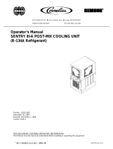
Crathco Beverage Freezers
Service Manual
for
Model 6321L
TABLE OF CONTENTS
Description........................................... 2 - 3
Unpacking............................................ 3 - 4
Assembly & Installation....................... 4 - 6
Sanitizing and Starting Unit ................6 - 8
Cleaning................................................. 9
Controls & Product Issues...................10 - 11
Operating Freezer..................................12
Service & Maintenance.........................13 - 15
Troubleshooting.................................... 16
Addendums........................................... 17 - 38
Prior authorization must be obtained from
Grindmaster Crathco Systems for all warranty claims.
Grindmaster Crathco Systems, Inc.
4003 Collins Lane
Louisville, KY 40245 USA
(502) 425-4776 (800) 695-4500
FAX (502) 425-4664
www.gcsworld.com
Grindmaster Crathco Systems, Inc., 2002
PRINTED IN USA
1102 Form # WH-324-03
Part # 90818
Model 6321L

The Model 6321L is a freezer that dispenses frozen carbonated alcoholic beverages (see photo on front cover).
The freezer has two major components, the freezer sections (dispense head) and the product feed system (lower
cabinet area). The freezer consists of a freezing cylinder with a rotating internal auger (dasher) that is belt driven by
an electric motor. The auger scrapes frozen product off of the inside of the refrigerated cylinder. A torque sensing
mechanism controls compressor operation to maintain desired product consistency. The freezer has an air-cooled
refrigeration system and is mounted on a product feed base cabinet. The cabinet contains a carbonator, pumps,
interrelated tubing, and components to store, mix, and transfer carbonated liquid mix to the dispensing head.
Both the freezer and base cabinet are enclosed in independent steel cabinets. The freezer cabinet panels are easily
removed to simplify installation, service and maintenance. The base cabinet has service doors located at the front
and back for service and maintenance. Mix out indicator lights notify the operator when one or all of the product
mixes are out.
The 6311 Frozen Dispenser is the upper portion of the 6321L only.
Unit Part Numbers: 6321L 6311
Overall Dimensions
Height 61 1/8 in
26 ¼ in.
Width 19 ¾ in 13 in
Depth 33 5/8 in
28 ¾ in
Operating weight: (approx.) 300 lbs.
150 lbs.
Shipping Weight: (approx.) 325 lbs.
175 lbs.
Compressor Horse Power: ¾ ¾
Refrigeration System:
Refrigeration Type 404a 404a
Refrigeration Charge (See data plate) .
…..Expansion valve setting 35 PSI 35 PSI
Ambient Operating Temp:
Minimum Temperature 40° F 40° F
Maximum Temperature 100° F 100° F
Electrical Requirements:
Operating Voltage 115 V 115 V
Current Draw 15 A 15 A
A CO2 cylinder supplies carbon dioxide gas to an adjustable carbonator regulator and an adjustable CO2 pump regu-
lator. The pump CO2 regulator delivers CO2 to both the gas driven alcohol pump and syrup pump. The process
starts when plain (tap) water enters a booster pump. The water is then pumped into the carbonator and carbonated.
Carbonated water flows through a manual shut-off valve to an electric solenoid that has a flow control. At the same
time, alcohol from the alcohol rack, located in the front cabinet compartment, flows to the gas driven alcohol pump.
The alcohol is then pumped through a manual shut-off valve to the alcohol electric solenoid with flow control. A gas
driven syrup pump draws concentrated syrup from the Bag-In-Box containers located at the bottom, front of the
lower cabinet. The syrup concentrate is then pumped through a manual shut-off valve to the syrup's electric solenoid
with flow control. If the freezing cylinder pressure drops below 25 PSI, the solenoids open and feed product through
a check valve into an accumulator. The carbonated water, alcohol and syrup concentrate are mixed together in the
feed line. The mixed product flows from the accumulator to the freezing cylinder.
A clear, self-closing, dispensing valve is attached to the front of the freeze cylinder barrel. A pressure release valve
is incorporated into the dispensing valve that allows excess CO2 to be vented when filling the freeze cylinder with
product. This pressure release valve will also allow excess pressure to escape the freezing cylinder.
Theory of Operation
General Description
SPECIFICATIONS
Page 2 Crathco Beverage Freezers

The freezer is equipped with an automatic defrost system to allow the frozen product to melt back to a liquid. This
eliminates any large ice crystal formation or poor product consistency that may develop. This automatic timer can be
pre-programmed to occur at desired times of the day. The defrost cycle takes four hours to complete and should be
programmed in.
The freezer has been operated and tested at the factory. Upon arrival the complete freezer
must be thoroughly checked for any damage which may have occurred in transit. NOTE: A
Tip (N) Tell warning device is placed on each shipping carton at the factory. If the arrow tip is
blue, the carton has been tipped in transit. (See Figure 1)
IMPORTANT: The carrier is responsible for all damage in transit whether visible or con-
cealed. DO NOT PAY THE FREIGHT BILL until the freezer has been checked for damage.
Have the carrier note any visible damage on the freight bill. If concealed damage and/or
shortage is found later, advise the carrier within 10 days and request inspection. The cus-
tomer must place any claim for damage and/or shortage with the carrier. The manufacturer
cannot make any claims against the carrier.
1) Read and understand the operating instructions in this manual thoroughly.
2) Note all warning labels on the freezer.
3) Do not wear loose fitting garments or jewelry that could cause a serious accident.
4) Stay alert at all times during operation.
5) Keep operating area clean.
Do not operate freezer if any excessive noise or vibration occurs. Contact an authorized service agent.
Safety and Inspection
Safety Precautions
Loose Parts Shipped with Unit
Unpacking and Inspection
Shipment and Transit
Figure 1
Crathco Beverage Freezers
Page 3
Part # Name Quantity
90881 Installation Guide 1
90882 Operators Manual 1
W0660060 Plastic parts bag 1
W0600121 Header installation instruction sheet 1
W0631903 Sanitizer packets 6
W0600159 Warranty card 1
W0890237 Drip pan kit 1
W0340022 “O” ring #213 6
W0660300 Dow Corning Silicone lubricant 1
W0480437 Plunger, Slush pressure 1
W0480445 Handle, valve 1
W0611728 Fas-Pin 1
W0631230 Compression Spring 1
W0660016 Silicone adhesive 1
W0610718 Screw 5/16-18 Hex Hd 2
W0611255 Washer, 5/16” lock 2
W0611086 Nut, 5/16” Hex, Zinc 2
60382 Heyco 1” snap bushing 1
90748 Silicone Nozzle 6
90749 Bottle Holddown Clamp 6
90750 Adjustment Knob 6
90770 90° Support 1
90878 Lock Washer #10 6
W0611254 Washer 2
W0631549 Coke® Cleaning Fitting 1

Periodic Inspection
Freezer Assembly and Installation
1) Check the CO2 tank pressure gauge on the cylinder regulator assembly. Replace if tank pressure drops below
red line.
2) Make sure the unit contains a sufficient supply of syrup and alcohol.
3) Check to see that there is sufficient air space on both sides of the unit. Proper air circulation is required for
efficient operation. Make sure that the louvers are not obstructed at any time. CAUTION: Failure to provide
minimum air flow clearance will void the freezer warranty. (See Locating Freezer)
1) Unbox freezer (top half)
a) Remove both side panels and then use a 7/16” socket to remove the 2
bolts at the bottom of the freezer that hold it to the shipping pallet.
b) Cut the wire tie (note red tag) on freezer drive motor. (Figure 2)
c) Leave right side panel (when facing front of freezer) off.
2) Place a bead of silicone sealant all the way around the edge of the base
cart top. (See Figure 3)
3) Place beverage freezer onto the base cabinet on top of the bead of silicone.
Position freezer over mounting holes before sealant sets. (Figure 4)
4) Secure top half of unit to base cart by installing 7/16" bolts and nuts using
the same holes used to secure the freezer to shipping pallet.
5) Open rear door of base cabinet and place black plastic bushing in wire hole in the top
of the cabinet.
6) Feed the 2-multi-pin connectors found in the freezer down into the base cabinet
through the hole in the top of the lower cabinet. Connect each connector from the
cabinet to matching connector in the freezer. (See Addendum 5)
CAUTION: Do not leave too much slack in the wires as they could get caught in the fan
blades. Use wire tie and holder to secure wires in place. See electrical diagram.
7) Remove the base cart electrical box cover (located in the upper right corner of the base
cart). Feed the power cord (found inside lower rear right side of freezer, near the terminals)
through hole into the base cart and then feed it into the hole in the rear of the electrical
box. Connect power cord wires. (See Addendum 3 and 4)
8) Route the product feed tubing (located in the freezer) down through hole into base cabinet.
Route the tubing to the top part of the freezer following the same path as the wiring.
9) Attach the tubing to the John Guest 90° elbow fitting which is located in the base cabinet behind the electrical
box. Make certain that the tubing is pushed all the way into the fitting. (Figure 5)
10) Replace freezer side panels.
11) Turn "on/off/clean" switch on front of unit to the OFF position.
Figure 2
Figure 3
Figure 4
90° Support
Product Feed Tubing
Figure 5
Attaching Freezer to Base Cart
Page 4 Crathco Beverage Freezers

1) The drip tray is mounted on two screws that are located on the lower front of the freezer cabinet.
2) Place the key hole slot of the drip tray support bracket W0471022 on to these screws and tighten the screws.
3) Angle the back of the drip tray surround bracket into the drip tray support bracket W0471022 and lower bracket
to lock it into place.
4) Place drip tray onto drip tray surround bracket.
5) Place the louvered drip tray insert into drip tray.
1. Locate freezer close to a source of potable water. Water pressure must be 15-psig or higher.
2. Connect freezer to a properly grounded 115-120 VAC, 60Hz single-phase electrical circuit with a 20-amp
(NEMA 5-20R) minimum-rated disconnect switch (not provided) that is fused at 20 amps (slow-blow).
CAUTION: Safe operation of this unit can only be achieved if the freezer is properly connected to an appro-
priate grounded, electrical receptacle that complies with current national safety standards. The manufactur
-
er cannot be held responsible for damage and/or injury caused by failure to connect the unit to an appropri
-
ate source of power.
3. A minimum air clearance of 6" is required on both sides of the freezer during operation.
CAUTION: Restricting air flow through the freezer will greatly reduce the output capacity as this is an "Air
cooled" unit. Air is drawn in to cool the unit through the right side (facing front of freezer) and exhausted
through the left side. Failure to provide minimum air flow clearance will void the freezer warranty.
1) Unscrew protector cap (with chain attached) from CO2 cylinder valve. Open CO2 cylinder valve slightly counter-
clockwise to blow any dirt or dust from outlet fitting before installing CO2 regulator assembly, then close valve.
CAUTION: CO2 cylinders contain gas under high pressure. Handle cylinders with care.
2) Remove shipping plug from CO2 regulator assembly coupling nut, then make sure gasket is in place inside the
nut. Install hose regulator assembly on the CO2 cylinder, then tighten coupling nut. DO NOT OPEN CO2
CYLINDER VALVE AT THIS TIME.
NOTE: Before attempting to activate the systems, insure that all manual shut-off valves, located in the lower back
compartment of the base cabinet, are closed (vertical position). Do not open them until instructed to do so.
1) Gather 3/8" OD low-density polypropylene tubing or 3/8" OD copper tubing with a
1/4” SAE Flare Connection (not provided).
2) Connect the tubing to the 1/4” SAE Flare fitting found under the left side of the
base unit. (Figure 6)
3) Connect the other end of the tubing to a water source.
NOTE: Where water quality is low an activated charcoal water filter may be needed
to achieve adequate frozen product overrun and proper flavor profile.
If water pressure exceeds 50 psig install a water regulator such as Shurflo
# 183-059-06, or equivalent, to inlet water line.
Figure 6
Attaching Drip Tray
Locating Freezer
Installing CO2 Regulator Assembly on CO2 Cylinder
Connecting City Water Source Line to Unit
The National Sanitation Foundation requires the following for an NSF approved water hook-up:
• A quick disconnect water connection or enough coiled tubing so that the machine can be moved for cleaning
underneath.
• An approved backflow prevention device, such as a double check valve to be installed between the machine and
water supply. On units plumbed to permanent water line, installation of a water filter/softener system is
recommended to prevent lime and scale build-up in the machine.
• Water pipe connections and fixtures directly connected to potable water supply shall be sized, installed and
maintained in accordance with Federal, State, and Local codes.
Installing CO2 Regulator Assembly on Existing CO2 Line
NOTE: Bulk system must have 100 psi to operate.
1) Purchase a low pressure regulator set. (Norgren Model C81-570-2 recommended)
2) Disconnect carbonator and BIB pump lines. Remove existing regulator set and install low pressure set.
3) Reconnect lines to outlet side of set. Bring in bulk system line to inlet of regulator.
NOTE: Install a cutoff valve between regulator and bulk system.
Crathco Beverage Freezers
Page 5

NOTE: CO2 regulators are pre-set at the factory. Check for accuracy.
1) Adjust the CO2 regulator that drives the bag-in-box syrup
pump and alcohol pump to 60 psi. Turning regulator
adjustment clockwise raises the pressure. Tighten locknut at
this setting. (Figure 7)
CAUTION: The use of excessive pressure (above 75 psi) will result in
pump seizure.
2) Adjust the CO2 regulator, connected to the carbonator, to
90 psi. NOTE: Do not exceed 120 psig, the carbonator pressure
relief setting. Turning regulator adjustment clockwise raises the
pressure. Tighten locknut at this setting.
Open the water line manual shut-off valve in the base cabinet of the 6321L and check for water leaks.
Adjusting CO2 Regulators
Activating Water Source Line Connection
Figure 7
Filling CO2 Lines
CAUTION: CO2 lines should be filled slowly to prevent the possibility of damaging components. Open tank shut off
valve slowly until it is completely open.
NOTE: Open valve all the way to prevent leakage around the valve shaft.
Page 6 Crathco Beverage Freezers
1) Prepare a minimum of 2 gallons (7.6 liters) of sanitizing solution (Divorsol CX or equivalent).
NOTE: Add 5 ounces (150 ml) of Divorsol CX to 2 gallons (7.6 liters) of 120° Fahrenheit (50° Centigrade)
water to achieve a concentration of 500 parts per million.
2) Disassemble the freezer following steps 1 through 8 in the Cleaning Section.
NOTE: For initial start-up, be sure to clean and sanitize the freezer before adding product.
3) After disassembly, thoroughly scour each part of the freezer in a warm mild detergent solution including
the inside of the freezing cylinder. Dip or wipe each part in sanitizing solution and allow to air dry on
clean paper toweling. DO NOT WASH COMPONENTS IN A DISHWASHER.
4) Rinse each part with clean water.
5) Reassemble components following the instructions in the Cleaning section of this manual.
6) Pour 1.5 quarts of sanitizing solution into both the front and back alcohol bottle rack.
7) Connect a red QCD cleaning fitting to one of the BIB connectors in the lower back cabinet and immerse the BIB
connector into the remaining solution.
NOTE: If a QCD cleaning fitting is not available, cut the plastic outlet fitting out of an empty BIB container.
8) Sanitize system by opening all three of the manual shut-off valves in the back
of the lower cabinet (syrup, alcohol and carbonated water).
9) Turn the freezer switch to "CLEAN".
10) Turn the control switch in the back of the base cabinet to "AUTO".
11) Allow the freeze cylinder to fill half way and run for 5 minutes.
12) Turn the freezer switch from "CLEAN" to "OFF".
13) Open the pressure relief valve located on the freezer dispensing valve to
relieve all of the pressure in the freeze cylinder.
14) Remove the QCD cleaning fitting from the first BIB line and place
it on the other BIB connection. Place second line in remaining solution.
15) Pull or push transfer valve to opposite setting.(Figure 8)
16) Repeat steps 9-12.
17) Remove BIB connector from container of sanitizing solution.
18) Purge sanitizer from product lines and barrel.
Figure 8
Sanitizing and Starting Unit
Sanitizing

Adding Product
Connecting Syrup Supply
1) Open new bag-in-box as instructed on box.
2) Connect red QCD syrup connector to new bag-in-box.
3) Repeat for second bag-in-box.
NOTE: Make sure that the BIB lines run behind the bottle rack line so the bottle rack can be slid open easily.
Crathco Beverage Freezers
Page 7
1) Remove bottle cap.
2) Slide a white tubular plastic adapter over the neck of each liquor bottle until the bottle
seats itself against the shoulder of the adapter.
3) Remove the blue plastic protective cap from reservoir port and save it.
4) Bend the nozzle of the white plastic adapter over with your forefinger to stop liquor flow.
(Figure 9)
5) Insert the nozzle of the white plastic tubular adapter into the reservoir port and allow
adapter to drop into the reservoir opening.
6) Stand inverted bottle upright.
7) Loosen the thumbscrew on the hold-down bracket and slide the hold-down bracket until it
is centered on the bottom of the bottle.
8) Push down on bracket until it firmly holds the bottle in place and tighten the knob.
Note: If you are using partially empty bottles place the emptiest bottle at the end of the
reservoir farthest from the reservoir outlet tubing. This will allow the partially filled bottle to be emptied first.
Figure 9
Connecting Alcohol Supply
NOTE: See Addendum 2 photo for location of components
1) Open manual valve located between gas powered alcohol pump and the alcohol electric solenoid with flow
control. This activates the alcohol supply system.
2) Open the manual valve between the gas powered syrup pump and the syrup electric solenoid with flow control.
This activates the syrup supply system.
3) Liquid should fill the lines and the pumps should cycle.
Activating Alcohol and Syrup System
NOTE: The water, syrup, and alcohol ratio are all pre-set at the factory to meet drink quality standards.
Adjustment of these ratios can only be done by authorized service technicians.
A graduated cylinder that holds at least 17 ounces (500ml) is needed to test the BRIX. A measuring cup can be
used if a graduated cylinder is not available.
1) Switch back cabinet control box switch (Figure 10) to "TEST" mode.
2) Switch Freezer control to "CLEAN".
3) Open test output port valve.
NOTE: See Addendum 2 for location of components.
1) Close all manual valves except the water valve.
2) Put test output port tube into the graduated cylinder.
3) Toggle "Sample Timer" switch to "ON".
4) Water will flow into the graduated cylinder for 10 seconds.
5) When water flow stops, measure the water volume in cylinder. The proper
setting is 13.5 oz. (400ml).
6) If the volume is not 13.5 oz (400ml), consult the Troubleshooting Guide in this
manual.
Syrup Ratio Check:
1) Close all manual valves except syrup.
2) Put test outlet port tube into the graduated cylinder.
3) Toggle "Sample Timer" switch to "ON".
4) Syrup will flow for 10 seconds.
5) When flow stops, measure syrup volume in cylinder. The proper setting is 3.7 oz. (110ml).
Water Ratio Check:
Checking BRIX (Water-to-Syrup Ratio) of Dispensed Product
Figure 10

6) If the volume is not 3.7 oz. (110 ml), consult the Troubleshooting Guide in this manual.
Note: Due to the thick viscosity of the syrup, it may be necessary to purge the syrup line to obtain an accurate flow
rate reading. Purge the syrup line by first closing the syrup valve, opening the water valve and then momentarily
turning on the test switch. This will purge all syrup from the lines and allow them to drain properly for a correct
reading of the syrup flow rate.
7) After the correct water and syrup flow rates are set, open both the water and syrup valves.
8) Turn the "TEST" switch to "ON".
9) Dispense mixed water and syrup though the test line.
10) Check the BRIX of the mix using a refractometer. Verify that the solution has a BRIX reading of 15.
Alcohol Ratio Check:
1) Close all manual valves except for "ALCOHOL".
2) Put test outlet port tube into the graduated cylinder.
3) Toggle "Sample Timer" test switch to "ON". Product will flow for 10 seconds.
4) When flow stops, measure volume in the graduated cylinder. The proper setting is 3.4 oz. (100ml).
5) If the volume is not 3.4 oz. (100ml), consult the Troubleshooting Guide in this manual.
Checking BRIX (Water-to-Syrup Ratio) of Dispensed Product (cont’d)
Page 8 Crathco Beverage Freezers
After checking all the ratios, open all manual valves. Open the cabinet's front and rear doors and check for any
leaks. If any leaks are located, contact an authorized service technician to fix the leak. Close and lock the front and
rear doors.
1) The timer is located inside the freezer back lit merchandiser box on the top front of the freezer. (Figure 11)
2) Rotate the timer dial, in the direction of the arrows, until the mark lines up with the current time of day.
3) The timer has a 2 week battery backup that requires 24 hours to charge fully.
1) Push all switch pin actuators toward the outer edge of the programming disk.
2) Set freeze time by pushing the switch pin actuators toward the center of the
programming disk. (Figure 11) An adequate defrost cycle should last
3-1/2 hours.
Note: Each pin actuator is equivalent to 15 minutes. Do not run a defrost for more
than 4 hours. May result in damage to seals.
1) Open all product manual control valves.
2) Set lower control box Power switch to "ON" and Sample Timer switch to "OFF" and Control Select switch
to “Run". (Figure 10)
3) Fill freezer with product
a. Turn freezer to "CLEAN", barrel will fill
b. When BIB pump stops switch freezer "OFF"
c. Open dispensing relief valve vent and relieve pressure. Close vent.
d. Repeat steps a-c until product reaches vent opening.
4) Switch freezer to "FREEZE" and allow approximately 15 minutes for product to reach proper frozen consistency.
Checking Unit for Syrup, CO2, and Water Leaks
Setting Clock (Time of Day)
Filling Freezer
Programming Defrost (Automatic)
Defrost Timer
NOTICE: For applications with extended periods between use (i.e. stadiums, arenas, special events) the freezer
must remain in “FREEZE” mode at all times, with a programmed defrost cycle. Turning the freezer “OFF” or unplug-
ging it with product in the cylinder can damage the seal, resulting in product leakage. If the freezer must be
unplugged or turned “OFF”, for a period of time exceeding 12 hours, it must be drained, cleaned and sanitized.
Contact a qualified service technician, such as ICEE Company, phone (800) 423-3872, to perform this service.
Freezer damage resulting from failure to follow this procedure is not covered under warranty.
Figure 11

NOTE: Before cleaning, all product should be drained from the freezing cylinder, pres-
sure vented, and either the valves set closed or product removed from the machine.
1) Disassemble the dispensing valve by first removing the dispensing valve pin
(Figure 12)
2) Push up on the dispensing valve plunger and pull out the dispensing handle.
The plunger assembly complete with spring and "O" Rings can then be removed
as a unit.
3) Remove knobs and carefully remove the freezer dispensing valve assembly.
4) Remove the O-Rings from the plunger assembly and back of the dispensing
valve body.
NOTE: The best way to remove an O-Ring is to first wipe off all of the lubricant using a clean
paper towel. Pinch the O-Ring upward with a dry towel between your index finger and thumb.
When a loop is formed in the O-Ring, roll it out of the groove with your other thumb. Always
remove the O-Ring farthest from the end of the plunger first. (Figure 13)
5) Carefully inspect the O-Rings for wear, nicks or cracking and replace if necessary.
6) Carefully pull out the auger assembly taking care to avoid damaging the rear seal
assembly at the back of the freezing cylinder.
7) Remove stationary portion of the shaft seal assembly (silicon carbide ring and rubber
boot) from the back end of the freezer cylinder. This is accomplished by reaching into
the cylinder and pulling the seal out with your index finger. (Figure 14)
8) Slide the rotary seal off of the auger shaft. (Figure 15) Inspect both seal compo-
nents carefully for nicks or cracks. Replace seal if defective. NOTE: To prevent
leakage both surfaces of the seal must be smooth with no chips or cracks.
9) Wash all components in a detergent solution, sanitize and allow to air dry.
DO NOT WASH COMPONENTS IN A DISHWASHER.
10) Wet the inner rubber lip of the rotary portion of the seal and the back end of the
auger shaft with water. Slide rotary portion of assembly onto the auger shaft, RUBBER
FIRST, with the smooth sealing surface facing toward the back of the auger.
11) Insert the stationary portion of the seal into the grooved rubber boot with the
polished surface facing out (forward), away from the rubber boot. Lubricate the
grooved rubber exterior portion of the boot with silicone lube and insert it straight
back into recess at the back of the freezing cylinder, RUBBER FIRST.
NOTE: On the circular portion of the seal, make sure that the groove is toward the
rubber (back of freezer).
12) Reassemble the dasher assembly, as shown in Fig.16. Insert the larger front and
smaller rear white plastic bearings into dasher, then slip in the stator rod. Carefully
and slowly guide the auger into the freezing cylinder taking care not to
damage the seal assembly. Turn auger shaft until it engages the square drive coupling.
13) Reassemble the dispensing valve assembly. (Fig. 12) Be sure to lubricate o-rings and relief vent
before assembling.
Figure 12
Figure 13
Figure 14
Cleaning
Figure 15
14) Thoroughly wash and sanitize all components. Inspect and lubricate
all surfaces of the large O-Ring and refit it into the rear of the valve
assembly. Install the valve assembly on the front studs and tighten knobs
until they are finger tight. Do not use tools to tighten knobs.
IMPORTANT: Failure to lubricate the large "O" Ring can result in product
leakage.
15) Reinstall the O-Rings on the plunger assembly and lubricate the O-Rings
and plunger. Reassemble the valve and replace the retainer pin.
Daily Cleaning of Unit
The exterior of the unit should be cleaned as needed, at the end of the operating day or during defrost cycle.
Remember to empty and clean the drip tray and drip tray bracket.
CAUTION: Course rags, abrasive cleaners, and excessive force can damage and/or destroy the surfaces of
this unit.
Crathco Beverage Freezers
Page 9
Figure 16

NOTE: The following product consistency (thickness) control adjustment procedure
requires removal of the right side panel. It is suggested that a qualified service
technician make this adjustment because side panel removal exposes hazardous
moving parts.
Warning: Do not attempt freezer adjustments until electrical power has been
disconnected.
It may become necessary to readjust the consistency setting (thickness) to
compensate for variations.
1) Disconnect electrical power.
2) Remove right side panel (facing freezer).
3) Use the adjustment screw located on the top, front of the drive motor mounting bracket to change product
thickness. (See Figure 17).
• Clockwise for thicker product consistency.
• Counterclockwise for thinner product consistency.
NOTE: It may require up to three 180° turns of this adjusting screw to see a noticeable change in product thickness.
4) Turn freezer to "ON" and allow it to freeze to desired consistency.
5) Wait 15 to 20 minutes, check product consistency (thickness) and repeat as needed.
6) Reinstall the side panel and reconnect power.
Figure 17
Consistency Adjustment
Controls and Product Issues
Mix Out Lights
Red indicator lights, located on the front of the freezer, illuminate if the unit runs out of CO2, syrup, water or alcohol.
When a light is on, the unit will not fill or freeze product.
Freezer Controls
NOTE: This dispenser has several power switches, that must be set in their operating position for the unit to operate
properly.
"ON/OFF/CLEAN" SWITCH
The "ON/OFF/CLEAN" switch is a three-position toggle switch located on the front of the freezer. The left (facing the
machine) position is the "ON" or freeze position. The middle position is the "OFF" position. The Right position is the
"CLEAN" position (the auger is turning but the compressor is off).
Lower Base Control Panel Switches
All of the following switches are located on the lower control box, inside the rear cabinet door. (See Addendum 2 at
the back of the manual)
Power Switch
This is the unit’s main power switch.
• On - power is supplied to the base unit.
• Off - No power is supplied to the base unit.
Control Switch
This switch determines whether the unit is in the test mode or operating mode.
• Test - The Test switch is used to check the BRIX of the product allowing the Timer Switch to control
the solenoids.
• Off - Turns off the product feed system.
• Run - Allows product to be automatically fed to the freezer.
Timer Switch
• On - Activates the 10 second timer use to test BRIX and mix ratios
• Off - Timer is de-activated (normal operating setting).
Faceplate Relief Valves
A spring-loaded pressure relief valve maintains a safe pressure in the freezing cylinder. When filling the cylinder the
relief valve acts as a vent to allow the CO2 and air trapped in the freezing cylinder to escape. Venting the freezing
cylinder is essential to obtain proper overrun. The vent is also used to break a vacuum when draining a unit.
Dispensing Valve
CAUTION: The product in the freezing cylinder is under pressure, open the dispensing valve slowly when
dispensing product.
Page 10 Crathco Beverage Freezers

BRIX
Correct BRIX effects product flavor and freezing characteristics. Frozen product with low BRIX may have a weak fla
-
vor, larger ice crystals, and a tendency to dispense slowly. Product with high BRIX has an overly strong flavor,
increased portion cost and results in lower freezer output capacity.
Alcohol Content
High alcohol content may prevent the freezer from serving product at proper thickness. High alcohol also suppress-
es the syrups ability to absorb CO2 and depresses the temperature of the frozen product. Too much alcohol will also
lower product overrun.
Overrun is the increase in product volume, expressed as a percentage, resulting from the carbonation of the water.
The freezer chamber is pressurized, which holds the carbonation in the frozen product. The carbonation causes the
volume of the frozen product to increase when dispensed. For example, if one gallon (4.4 liters) of liquid mix is fed
into a freezing cylinder and one and a half gallons (6.6 liters) of frozen product is drawn out, the result is a fifty per-
cent volumetric increase, or a fifty percent (50%) "overrun".
Why is overrun important? The introduction of CO2 into the finished frozen product is essential from two stand-
points...taste and profitability. Frozen product that has a low percentage of overrun costs more to serve, appears
wet, and is heavy. The introduction of CO2 makes the finished frozen product taste richer. Too much overrun causes
the finished frozen product to be too light and fluffy, making it less satisfying and adversely effecting sales.
Product Quality
What Is Overrun?
Factors Effecting Overrun
Syrups
The foaming agent in the syrup increases the ability of the frozen product to expand as it is dispensed.
Frozen Product Draw Rate Effects Overrun
Infrequent frozen product usage can result in a drink that may appear wetter and have less overrun.
Carbonation In The Water Effects Overrun.
There is a direct correlation between the level of carbonation of the water and the overrun of the frozen drink. Water
quality has a direct effect on carbonation. If it is difficult to achieve adequate overrun an activated carbon filter will
have to be added to the system. Also try readjusting the carbonator CO2 pressure.
Computing Overrun
1) Weigh an empty cup.
2) Weigh this cup filled to the rim with liquid mix, and subtract the weight of the cup.
3) Draw a heaping cup of frozen product that contains no air pockets. Avoid tapping the cup as this artificially
reduces overrun.
4) Use a straight edge to scrape off excess product flush with the rim of the cup and weigh the cup.
5) Subtract the cup weight and use the overrun formula to determine overrun.
For Example:
If a full cup of liquid mix weighs 23 ounces (.652kg) and a full cup of frozen product weighs 15 ½ ounces (.439kg),
then:
23 - 15½ X 100 = 48.4% Overrun
15½
Weight of
Liquid Mix
Weight of
Frozen Product
Weight of Frozen Mix Product
X 100 = OVERRUN
Crathco Beverage Freezers
Page 11

Operating Freezer
Unit Operation
1) Check that a "Mix Out" light is not illuminated. This indicates the freezer has an adequate amount of syrup,
CO2, alcohol and water (only one light will be ON at a time). Check machine after each product is filled.
2) Insure that the "ON/OFF" switch in the lower back compartment of the cabinet is in the "ON" position.
3) Insure that the "TEST/OFF/RUN" switch in the lower back compartment of the cabinet is in the "RUN" position.
4) Insure that the "ON/OFF/CLEAN" switch on the front of the freezer is in the "ON" position.
5) Allow the freezer sufficient time to reach desired product consistency (compressor will shut off).
6) Slowly open the dispensing valve to dispense frozen product.
7) If frozen product consistency is not correct, readjust following the instructions found in the PRODUCT
CONSISTENCY section of this manual.
Replenishing Syrup Supply
A vacuum transfer valve will automatically switch from an empty BIB container to a full one. Check BIB containers on
a regular basis and replace empty BIB following the procedure in the CONNECTING SYRUP SUPPLY section of this
manual.
Replenishing CO2 Supply
1) Open rear cabinet door.
2) Turn CO2 cylinder valve clockwise until it is fully sealed.
3) Detach Regulator assembly.
CAUTION: Remove connector slowly to relieve pressure build-up in the lines.
4) Unhook S-hook from safety chain.
5) Remove empty CO2 cylinder.
6) Slowly crack the valve on the new CO2 cylinder to blow any debris out of the valve.
7) Close the valve.
8) Place new CO2 cylinder in the place of the used CO2 cylinder.
9) Make sure that the CO2 regulator assembly coupling nut gasket is undamaged.
10) Attach the regulator hose on the new CO2 cylinder.
CAUTION: The CO2 lines need to be pressurized slowly to insure they are not damaged. Open the tank shut off
valve slowly until it is fully open. NOTE: Opening the valve all the way prevents leakage around the valve shaft.
Replenishing Alcohol Supply
1) Remove empty alcohol bottles.
2) Remove white tubular adapters from bottles.
3) Remove caps from new bottles and slide white plastic adapter over the neck until the bottle seats itself against
the shoulder of the adapter.
4) Bend the nozzle of the white plastic adapter over with your forefinger to stop liquor flow.
5) Insert the nozzle of the white plastic adapter into the reservoir port and allow adapter to drop into the reservoir
opening.
6) Stand inverted bottle upright.
7) Loosen the thumbscrew on the hold-down bracket and slide the hold-down bracket until it is centered on the
bottom of the bottle.
8) Push down on bracket until it firmly holds the bottle in place…tighten the knob.
9) Repeat for each bottle
Note: If you are using partially empty bottles place the emptiest bottle at the end of the reservoir farthest from the
reservoir outlet tubing. This will allow the partially filled bottle to be emptied first.
Page 12 Crathco Beverage Freezers

Service and Maintenance
Servicing Dispensing Valves, O-Rings, and Freeze Cylinder Drive Shaft/Seal Assemblies
NOTE: Dispensing valve "O" Rings should be replaced every 120 days to correspond with quarterly preventative
maintenance visits.
The best technique for removing an "O" Ring is to first wipe off all of the lubricant using a clean paper towel. Pinch
the "O" Ring upward with a dry towel between your finger and thumb. When a loop is formed in the "O" Ring, roll it
out of the groove with your thumb. Always remove the "O" Ring farthest from the end of the plunger first. (See
Figure 13)
Crathco Beverage Freezers
Page 13
Quarterly Preventative Maintenance
Quarterly Preventative Maintenance is recommended to extend the life of the machine. Preventative Maintenance
visits include sanitizing the entire system, checking for and replacing any worn parts, optimizing operating
conditions. See the parts replacement schedule at the end of this section.
Sanitizing Entire Liquid Systems
It is essential that the entire liquid system be sanitized every 3 months by a qualified technician. Follow the above
instructions.
NOTE: Clean and sanitize the entire liquid system before and after storage.
Routine Product System Sanitizing
Note: During sanitizing, all "O" Rings and seals should be inspected for damage
1) Drain product from freezing cylinder barrel
a) Turn freezer switch to "CLEAN".
b) Close manual syrup feed valve in back lower compartment of the cabinet.
c) Close manual alcohol feed valve in back lower compartment of the cabinet.
d) Place container under product dispensing valve, open dispensing valve handle.
e) Continue to remove product until it starts to become semi-clear and has a liquid consistency.
f) Close manual carbonated water feed valve in back lower compartment of the cabinet.
g) Drain remaining product. If liquid flow stops before the freezing cylinder is empty pull vent (round
ring) in valve block and break vacuum.
2) Remove product from BIB supply lines
a) With freezer in "CLEAN" mode, disconnect BIB connectors.
b) Open manual syrup valve in back lower compartment of the cabinet.
c) Place a container under test line and open test port manual valve.
d) Turn the control switch in lower cabinet to "TEST".
e) Turn test switch to "ON".
f) Allow pump to operate until it stops.
g) Move BIB connector to other BIB container and repeat steps (e) and (f) above.
h) Install a cleaning connector to BIB connector that is indicated as active by the switch on the BIB
vacuum transfer valve.
i) Put line with connector into a container of clean water.
j) Repeatedly cycle the "TEST" switch to "OFF" then to "ON" until the line is clear of syrup.
k) Repeat process for alternate BIB hose starting at (g) above.
l) When the syrup lines are clean close the manual syrup line valve.
3) Remove product from Alcohol supply lines
a) With freezer in "CLEAN" remove the alcohol bottles from storage rack.
b) Open the manual alcohol valve in the back lower compartment of the cabinet.
c) Place a container under test line and open manual test port valve.
d) Move control switch in lower cabinet to "TEST". Turn test switch to "ON".
e) Allow pump to operate until it stops or all alcohol is removed.
f) Pour clean water into the alcohol rack reservoir .
g) Cycle the test switch from "OFF" to "ON" until the line is clear of alcohol.
h) When lines are clean close the manual valve on alcohol line.
Complete the sanitizing procedure by following the steps in the Sanitizing & Starting Unit Section.

Drive Belt Adjustment
CAUTION: Unplug the machine before performing any adjustments.
Check the belt tension quarterly. Proper belt tension is ½" deflection
measured mid way between the drive and driven pulleys. If the deflection is
more than ½" adjust the motor height to achieve proper tension using the
following procedure:
1) Unplug the unit and remove the side and rear panels.
2) Locate the motor flange bearings (W0380009) located at each end of
the drive motor. Two bearings support the motor, one on the shaft at
each end of the motor. The bearings are secured to the motor cradle
using two Allen bolts on each bearing.
3) Loosen all four bearing Allen bolts. NOTE: Do not loosen the setscrews
that hold the bearing collars to the motor shaft.
4) Lower or raise the motor as needed to achieve proper belt tension. The motor must be kept level from front
to back. NOTE: Excessive belt wear and belt noise can occur if the motor is not kept level.
5) Tighten all four Allen bolts down.
6) Align the driven motor pulley with the top driven pulley if needed. Use a straight edge along the top pulley. If the
pulleys are not in alignment, remove the setscrew from the pulley and move either in or out as needed.
NOTE: Use non-permanent Loc-Tite on the driven pulley setscrew and tighten down on the flat of the motor shaft.
Page 14 Crathco Beverage Freezers
Lubricating Plunger O-Rings
1) Close syrup and alcohol manual control valves located in the back compartment of the lower cabinet.
2) Place freezer in "CLEAN" position.
3) Drain freeze cylinder while purging with carbonated water.
4) Turn freezer control switch to the "OFF" position.
5) Vent pressure and drain completely.
6) Remove dispensing valve plunger.
a) Remove valve handle retaining pin.
b) Push plunger up and remove handle.
c) Pull plunger down.
7) Remove "O" Rings and clean "O" Ring grooves.
8) Replace "O" Rings.
9) Lubricate the "O" Rings on the plunger and the area inside of the clear plastic valve body where the plunger
"O" Rings make contact with the valve body using silicone lubricant.
10) Replace Plunger assembly.
a) Place spring on top of plunger.
b) Place plunger in valve body making sure that the handle opening faces forward.
c) Push up on plunger and replace handle.
d) Insert handle retaining pin.
e) Sanitize unit following instructions in manual.
11) Refill unit following instructions in manual.
Note: Plunger o-rings, face plate quad ring, shaft seal set, motor belt, etc. should be replaced annually.
Changing Back Lit Sign Merchandiser Bulb
1) Remove the two screws, located on the top on either side of the sign.
2) Lower the metal enclosure that frames the merchandiser insert.
3) Pull merchandiser enclosure down and out.
4) Replace bulb inside.
5) Reassemble.
Cleaning Condenser Coil
1) Turn machine "OFF".
2) Remove both freezer side panels.
3) Place a wet towel on the inlet side of the condenser (right side facing front of freezer).
4) Use compressed air to blow out condenser coils from the exhaust side of condenser coil (fan motor side).
NOTE: Follow all health and safety standards.
5) Replace side panels.
Figure 18

Part Description Monthly Every
3 Months
Every
6 Months
Annually Quantities to
be Replaced
Drive shaft seal
W0340210
Inspect &replace
if necessary
Replace 1
Drive shaft
W0451067
Inspect & replace
if necessary
1
Drive belts
W0450209
Inspect & replace
if necessary
1
Scraper blades
on dasher
W1431084
Replace 2
Square cut o-ring on
valve body/face plate
W0340055
Inspect &replace
if necessary
1
Front stator flange
bearing
W0430032
Inspect &replace
if necessary
1
Rear stator flange
bearing
W0430024
Inspect &replace
if necessary
1
Dispense valve o-rings
W0340022
Replace 3
Dispense valve
relief valve
W0650429
Inspect &replace
if necessary
1
Inlet tube o-rings
W0340011
Inspect & replace
if necessary
2
Condenser
W0200256
Inspect & clean if
necessary
1
Alcohol Holder
components
90750 - knob
90749 - clamp
90748 - nozzle
Inspect &replace
if necessary.
Nozzle
replacement
mandatory.
6
Alcohol, syrup, &
water solenoid 90863
Inspect & replace
if necessary
3
Alcohol, syrup pump
90729 and
Water pump 61290
Inspect & replace
if necessary
2 - CO2 Driven,
1 - Electric
Alcohol rack Disassemble and
sanitize
Parts Replacement Schedule
Crathco Beverage Freezers
Page 15

Problem Probable Cause Remedy
Machine won’t run (no lights,
not motor)
• Machine not plugged into wall receptacle
• Building circuit breaker tripped or fuse
blown
• Switches in wrong position
• Plug machine directly into outlet. Do not
use extension cord.
• Place circuit breaker in the ON
position or replace fuse
• Turn lower panel Power Switch to ON,
Control Switch to OFF and freezer switch
to ON.
Machine will not freeze • Dasher assembly not installed
• Drive belt broken or off pulley
• Inadequate airflow
• Freezer in CLEANposition
• Mix low light on indicating an out of condition
• Condenser clogged
• Compressor not operating
• Low refrigerant charge
• Improper expansion valve setting
• Defrost timer set
• Install dasher assembly
• Repair or replace
• Allow 6” (15cm) on both sides
• Switch to ON
• Correct out of condition (syrup, water,
alcohol, or CO2)
• Clean condenser
• Check for cause and correct
• Check for leaks, repair and recharge
• Adjust within specifications
• Wait for defrost cycle to end
Product too soft (thin) • Consistency adjuster too thin
• Too much alcohol
• Product BRIXlevel too high
• Readjust consistency firmer
• Readjust alcohol flow control
• Check water and syrup flow controls for
proper test volume
Product too thick (firm) • Consistency adjuster set too firm
• Too little alcohol
• Product BRIXlevel too low
• Readjust consistency setting thinner
• Increase product BRIXlevel and check
product feed
• Increase product BRIXlevel
Product will not dispense • Power switch OFF
• MIX LOW light on
• Drive belt broken or off pulley
• Turn power switch ON
• Refill empty product
• Repair or replace
Leakage from drip tube • Worn out or defective drive shaft seal • Replace seal and then lubricate at each
cleaning
Excessive Dispensing Valve
Leaks
• Worn or defective o-ring(s) • Replace and lubricate at each cleaning
Clicking sound from inside the
machine
• Low voltage
• Extension cord is used
• Use dedicated circuit with proper rating
• Connect directly to power source or use
power cord of proper size
Thumping sound from inside the
machine
• Worn belt
• Low alcohol content
• Replace belt
• Check mix
Product does not feed • Low CO2 pressure
• Product pumps defective
• Carbonator pump defective
• Transformer defective or transformer
overload tripped
• Solenoids defective
• Check bottle and regulator
• Replace pumps
• Replace pumps
• Replace transformer or reset transformer
circuit breaker
• Replace solenoids
Premature seal wear • Incorrect installation of dasher
• Improper drive shaft clearance
• Advise careful installation
• Adjust to proper clearance
Troubleshooting Guide
If machine is not operating properly, check the following list for possible solutions. Only a qualified service technician
should perform electrical and mechanical adjustments or repairs. Always disconnect power before attempting any
maintenance procedures.
If you still need help, call an authorized dealer in your area or GCS’ Technical Service Department. You can reach
Technical Service at (800) 425-4776 Monday-Friday, 8:00 AM-6:00 PM Eastern Standard Time. Please have the model and
serial number ready so that accurate information can be given.
Prior authorization must be obtained from Grindmaster Crathco Systems’ Technical Service Department for all
warranty claims.
Page 16 Crathco Beverage Freezers

Addendum 1 - Complete Unit Exploded View
ITEM PART # DESCRIPTION
1 W0150590 Stock Assembly
2 00800 Serial Label
4 W0800120 Base Board Assembly
5 W0800121 Shipping Box
6 W0800122 L-Block
7 W0800124 Foam Top Carton Pad
8 W0340210 Coconut Oil Seal
9 W0430089 Scraper Dasher
10 W1431084 Scraper Blade
11 W0890235 Kit, Panel Black
12 W0340055 O-ring, Valve Body
13 W0610133 Panel Screws
14 W0480460 Body, Valve Pressure
ITEM PART # DESCRIPTION
15 W0630711 D-Knob, w/ 5/15-18 Female Threads
16 W0650429 Pressure Relief Valve, Modified
17 W0631238 Spring, Extension Yellow
18 W0610574 1/4-20 Hex Head Cap Screw
19 W0611074 1/4-20 Hex Nut
21 W0611242 Flat Washer
22 86823 1/4 LockWasher
23 W0430024 Stator Flange Bearing (Rear)
24 W0430028 Stator Weldment
25 W0430032 Stator Flange Bearing (Front)
26 60832 Bushing, Heyco 1” Snap
27 90822 Patent Pending Label
28 90719 Cart, Carbonated Alcohol Injected
29 W0660058 Plastic Shipping Bag
Crathco Beverage Freezers
Page 17
11
11
11
15
16
14
12
9
10
10
24
23
8
25
1
28
28

Page 18 Crathco Beverage Freezers
Regulators
Alcohol Valve/Control
Syrup Valve/Control
Test Port
Water Valve/Control
Carbonator
Water Pump
Addendum 2 - Base Cabinet
POWER
ONOFF
SAMPLETIMER
OFF ON
CONTROL SELECT
OFF
TEST
RUN

Addendum 3 - Electrical Connections in Lower Cabinet
Addendum 4 - Electrical Connections in
Lower Cabinet
Addendum 5 - Electrical Connections
Cabinet to Freezer
Crathco Beverage Freezers
Page 19
29
28
27
31
35
57
60
58
62
59
63
64
VIOLET / WHT
VIOLET / WHT
WHT / BLK
YELLOW / BLK
BLACK / WHT
64
59
63
62
57
62
35
31
60
58
31
35
57
60
58
62
59
63
64

Addendum 6 - 6321 Base Cabinet Electrical Schematic
ITEM PART NUMBER DESCRIPTION
30 W0570045 BALLAST
61
W0570235
TERMINAL BLOCK
32 90811 TIMER
33 61847 POWER SWITCH
34 61847 TIMER SWITCH
45 W0570924 SWITCH
36 COMES WITH
CARBONATOR
FLOAT SWITCH
37 90834 PUMP
38 W0570044 LIGHT SOCKET
39 W0570043 LIGHT BULB
40 90857 SYRUP AND ALCOHOL SOLENOIDS
41 W0650415 SOLD OUT SWITCH
42 W0650400 BARKSDALE PRESS. SWITCH # MSPS-JJ100SS-F
43 90858 WATER SOLENOID
44 90879 ALCOHOL FLOAT SWITCH
Page 20 Crathco Beverage Freezers
29
28
27
60
57
35
31
64
63
59
62
58
15
19
30
32
33
34
45
21
20
64
14
23
24
59
24
13
25
22
23
24
63
25
61
18
21
16
17
28
27
62
30
30
6232
32
29
33
18
17
34
33
26
37
36
58
6
44
42 42
41
43
40
57
62
8
8
35
7
31
7
60
9
10
11
12
13
14
39
38
16
15
/