Page is loading ...

©2017 Flavor Burst Company Printed in September Printed in
All Rights Reserved The United States of America
Flavor Burst
®
Jumbo Touch Panel FCB
Frozen Carbonated Beverage System
JBT 80FCB-2B
compatible with Taylor C300 freezers
JBT 80FCB-3B
compatible with Taylor C303 freezers
JBT 80FCB-4B
compatible with Taylor C314 & C302 freezers
Equipment, Maintenance and
Operations Manual
Manufactured by
Flavor Burst Company
499 Commerce Drive
Danville, IN 46122
For general information and to locate a
distributor near you, call or visit our website:
Phone: (317) 745-2952
Toll Free Number: (800) 264-3528
Fax: (317) 745-2377
www.flavorburst.com
For pricing, ordering and support, contact one
of our qualified distributors.
Warranty
An installation and warranty form is provided with every Jumbo Touch Panel system, located inside the
cabinet unit with this manual. It is important that the operator carefully review the warranty and
installation documents accompanying the unit before using this system. Any questions or concerns
regarding the warranty should be clarified upon delivery or installation. For more information, contact
your local authorized Flavor Burst
®
distributor.

1
TABLE OF CONTENTS
Introduction……………………………...………………………………………….………….4
Safety Precautions……………………………..…………….………..……..….…………....4
Environmental Notices………………...………………………………………….………….5
Parts Identification/Functions...……...………………………………………….………….7
Replacing the Syrup Flavors…………...…………………………..…….………...……...28
Scheduled Maintenance…………...……………………………….…….………...…...….32
Clean-In-Place (CIP) Procedure…………………………………....…………..…....32
CIP – Phase 1: Prep………………………...…………………………….......32
CIP – Phase 2: Flush……………………………….....……………….......…33
CIP – Phase 3: Clean………………………………………….……….......…34
CIP – Phase 4: Reassemble………………………………….……….......…35
Priming the Syrup System………………………………….....…………...….......…36
Refilling the Sanitizer Tank…………………………………..........……………....…37
Cleaning the Door Spout Assembly……………………………….....…………......37
Cleaning / Replacing Syrup Port O-Rings……...…….…………......…………...…38
Miscellaneous Cleaning Procedures…………………………………………......…39
Area Under the Cabinet………………………………….....……………...…39
Inside the Cabinet………………………………….....………………….....…39
9-Tube Assembly Casing………..………………………….………….…..…39
9-Tube Assembly Syrup Lines……………………....……………….…....…40
Jumbo Touch Panel Assembly……………….…...………....…………...…40
Winterizing the Unit ………………………………..…………...……………..…...…41
Equipment Setup……………………………………………………...…..……….……..….44
Installing the Door Spout Assembly...………………………..…………………...…44
Mounting the 9-Tube Assembly Casing ……………………….………………...….46
Mounting the Jumbo Touch Panel Assembly...…………….……………...….....…47
Mounting the Plastic Casing Assembly..……………………...……...……….....….49
Connecting the Unit Syrup Line……………………………………………….......…50
Installing and Filling the Sanitizer Tank………………………….…………….....…50
Power Connections and Power Up……………………………………….…........…51
Installing Flavors and Priming Syrup Lines………………………...……….…...….52
Adjusting the Base Product Flow Rate……………………………...……….…...…54
Jumbo Touch Panel Overview.…….………………..…………………………..........…...56
Quick Reference Guide for Jumbo Touch Panel Setup..…..……...…….………...56
Testing the Jumbo Touch Panel System…..…….…………………………........…57

2
TABLE OF CONTENTS (continued)
Directory of Cleaning Procedures……………………………...………………..…….….61
Parts Replacement Schedule………...………………….………………..….……………61
Recommended Maintenance Items Replacement Schedule………………....…....…62
Alternate Parts and Kits by Freezer Model……………………………...……...…....….62
Ordering/Service Information…………….…….…...…………………..……….........…..63

3
PAGE INTENTIONALLY
LEFT BLANK

4
Congratulations on your purchase of a Jumbo
Touch Panel “JBT” flavoring system! As a food
and beverage provider, your customers are
your greatest asset. Your primary concern
must be the health and welfare of your
customers. This manual provides everyday
operating guidelines and procedures. Special
functions have been incorporated into the
equipment to provide simple and effective
cleaning and sanitizing of your unit. We urge
you to follow these instructions carefully and
maintain strict sanitary practices in your daily
operating routine.
The Jumbo Touch Panel system is an add-on to
a frozen beverage freezer designed to blend
concentrated flavorings throughout frozen
beverage product as it is dispensed. Dispensing
Flavor Burst product is very simple. Select a
flavor from the Jumbo Touch Panel and draw
the product. The Flavor Burst system will
automatically flavor the product at the spout.
You can also have multiple flavors per serving.
Simply select the flavors from the Jumbo Touch
Panel and draw the product. The system will
switch from one flavor to the next in a smooth,
continuous motion, layering the serving with
different, delicious flavors.
The Jumbo Touch Panel is a large interactive
touch panel. Not only do you select flavors
from this screen, it is also an advertising tool
used to attract customers. Images, information
and videos can all be displayed on this screen.
Flavor Burst
®
syrup is stored within the
equipment cabinet in 1 gallon disposable bags.
Proper syrup injection rate is maintained by
adjusting the flavor level on the Touch Panel.
Currently, the Jumbo Touch Panel system has
models compatible with Taylor C300, C303,
C314, and C302 freezers where the light box
display is mounted on the top of the freezer.
Components of the Jumbo Touch Panel system
should be cleaned regularly to ensure the
highest standard of sanitation. Follow the
instructions in the SCHEDULED
MAINTENANCE section to comply with
sanitation guidelines.
NOTE: PARTS AND PART NUMBERS MAY
VARY FROM WHAT IS SHOWN AND LISTED.
CONSULT YOUR LOCAL DISTRIBUTOR IF
YOU HAVE ANY QUESTIONS CONCERNING
DIFFERENCES.
Always follow these safety precautions when
operating the Flavor Burst
®
system:
DO NOT operate the system without
reading this operator’s manual. Failure to follow
this instruction may result in equipment
damage, poor system performance, health
hazards, or personal injury.
DO NOT operate the system unless it is
properly grounded. Failure to follow this
instruction may result in electrocution.
DO NOT operate the system with larger
fuses than specified on the system data label.
Failure to follow this instruction may result in
electrocution or damage to the machine.
Consult your electrician.
DO NOT put objects or fingers in the
door spout. Failure to follow this instruction may
result in contaminated product or personal
injury from blade contact.
The JBT cabinet system must be placed
on a level surface capable of supporting at least
220 lbs of weight. Failure to comply may result
in personal injury or equipment damage.
DO NOT place more than 25 lbs of
weight on top of the cabinet. Failure to comply
may result in personal injury or equipment
damage.
DO NOT install the unit in an area where
a water jet could be used, and do not use a
water jet to clean or rinse the system. Failure to
follow these instructions may result in serious
electrical shock.
SAFETY PRECAUTIONS
INTRODUCTION

5
HAZARD COMMUNICATION STANDARD
(HCS) – The procedure(s) in this manual
include the use of chemical products. These
chemical products will be highlighted in
bold-faced letters followed by the
abbreviation (HCS) in the text portion of the
procedure. See the Hazard Communication
Standard (HCS) manual for the appropriate
Material Safety Data Sheet(s) (MSDS).
NOISE LEVEL: Airborne noise emission
does not exceed 70 dB(A) when measured at a
distance of 1.0 meter from the surface of the
machine and at a height of 1.6 meters from the
floor.
NOTE: Operations Manual subject to
change. Contact your local distributor for most
recent updates concerning the Jumbo Touch
Panel unit.
NOTE: Access to the service area is
restricted to persons having safety / hygiene
knowledge and practical experience of the
appliance.
NOTE: This appliance can be used by
children aged from 8 years and above and
persons with reduced physical, sensory, or
mental capabilities or lack of experience and
knowledge if they have been given supervision
or instruction concerning use of the appliance in
a safe way and understand the hazards
involved.
NOTE: Children shall not play with the
appliance.
NOTE: Cleaning and user maintenance
shall not be made by children without
supervision.
ENVIRONMENTAL NOTICES
If the crossed out wheeled bin symbol is affixed to this product, it signifies that this product
is compliant with the EU Directive for Waste Electric/Electronic Goods (WEEE) as well as
other similar legislation in affect after August 13, 2005. Therefore, it must be collected
separately after is use is completed, and cannot be disposed of as unsorted municipal
waste.
The user is responsible for returning the product to the appropriate collection facility, as specified by your
local codes. For additional information regarding applicable local laws, please contact the municipal
facility and/or local distributor.

6
PAGE INTENTIONALLY LEFT BLANK

7
General System Overview (See Figure 1)
ITEM PART NO. DESCRIPTION QTY. FUNCTION
1-1
ELE 950JBT
JUMBO TOUCH PANEL ASSEMBLY
- 2B / 3B
1
JBT 80FCB-2B & JBT 80FCB-3B
SYSTEMS:
Flavor Burst unit command center for 2 and 3
barrel systems.
OR…
1-2
ELE 970JBT
JUMBO TOUCH PANEL ASSEMBLY
– 4B
1
JBT 80FCB-4B SYSTEMS:
Flavor Burst unit command center for 4-
barrel systems.
2
ELE 434 POWER CABLE 1 Supplies the electronics board with power.
3
N/A
MODIFIED FREEZER SPOUT
ASSEMBLY FOR JBT
1 Dispenses product mixed with flavorings.
4
MIS 3196
STAINLESS TUBE / CABLE CASING
ASSEMBLY
1
Attaches the flavor lines and/or cables to the
side of the freezer.
5
SPR 5800FCB
SPARE PARTS KIT TOUCHSCREEN
BEVERAGE
1 Houses extra spare parts and wear items.
6
CAB 113 FLAVOR TRAY 8 Houses syrup bags.
7
N/A
FLAVOR BURST FROZEN
BEVERAGE CABINET ASSEMBLY
1 Houses syrup trays and bags.
8
SAN 740 SANITIZER TANK ASSEMBLY 1 Houses sanitizer cleaning solution.
9
SYR 944SH
SYRUP BAG CONNECTOR
ASSEMBLY - SHAKE
8 Transports syrup from the bag to the pumps.
10
MIS 3026S
JUMBO TOUCH PANEL CABLE
CASING
1
Conceals and protects the Jumbo Touch
Panel cable, as well as attaches it to the
freezer.
11
MIS 3302K C300 CONVERSION BRACKET 1
JBT 80FCB-2B SYSTEMS:
Allows the Jumbo Touch Panel to be
mounted to a C300 freezer.
ITEM PART NO. DESCRIPTION QTY. FUNCTION
A
ADPT TY80S-
FCB1CTP
CTP / JB AUTO DRAW VALVE
UPGRADE KIT
1
Replaces a manual draw spout assembly
with a push-button spout assembly and an
on-screen dispense button.
*THIS KIT IS OPTIONAL AND SOLD SEPARATELY. CONTACT YOUR LOCAL DISTRIBUTOR.
PARTS IDENTIFICATION/FUNCTIONS

8
General System Overview
Figure 1

9
Cabinet – (See Figure 2)
ITEM PART NO. DESCRIPTION QTY. FUNCTION
1
N/A ELECTRONICS SYSTEM 1 Houses microprocessor and electronics.
2
CAB 135R-A
RIGHT SIDE PANEL 1 Holds tray support brackets and panel brackets.
3
CAB 145 TRAY SUPPORT BRACKET 8 Supports flavoring trays.
4
FAS 2024 8-32 X 1/4 PAN HEAD 28
Fastens panel brackets to divider panel, secures
sides.
5
FAS 2014 8-32 X 1/2" PAN HEAD 25
Attaches top panel, back cover, and feet to
cabinet.
6
ELE 483 SANITIZER PUMP CABLE 1 Provides power to the sanitizer pumps.
7
ELE 932
PUMP & SANITIZER CABLE
HARNESS
1 Provides power to the syrup and sanitizer pumps.
8
MIS 3066 MINI BUSHING 1 Protects flush tube.
9
MIS 3028-S
FLUSH TUBE ASSEMBLY -
SHAKE
1
Connects with flavor line to flush with sanitizer
solution.
10
CAB 139 FRONT DOOR PANEL 1
Provides easy access to syrup bags and
connectors.
11
CAB 136-A
REAR PUMP COVER 1 Back panel to cover pumps.
12
FIX 1023
3/16" X 3/16" BARB TUBE
CONNECT
1 Splices together flush tubes.
13
CAB 134 DIVIDER PANEL 1
Holds tray support brackets and divides
flavor trays.
14
CAB 144R RIGHT PANEL BRACKET 3 Holds tray support rails.
15
CAB 144L LEFT PANEL BRACKET 3 Holds tray support rails.
16
CAB 143 LATCH BRACKET 1 Provides latching tab for front panel latch.
17
FAS 2001 FRONT DOOR PANEL LATCH 1 Latches front door to cabinet front.
18
SYR 927 INTERNAL 9-TUBE ASSEMBLY 1
Transports syrup from bags to flavor
9-Tube Assembly.
19
SAN748 PERISTALTIC SANITIZER PUMP 1
Pumps sanitizer solution to flush tube and neutral
base to purge the spout.
20
SYR 926 PERISTALTIC SYRUP PUMP 8 Pumps syrup from flavor bags to flavor lines.
21
CAB 155L PUMP MOUNTING STRIP 1
Support for syrup trays and spacing between
panels.
22
CAB 155R PUMP MOUNTING STRIP 1
Support for syrup trays and spacing between
panels.
23
FAS 2037 TAPPED NYLON SPACER 12
Secures screw to center panel, and support for
trays.
24
FAS 2032 STANDARD NYLON SPACERS 12 Provides extra support for flavor trays.
25
FAS 2034 8-32 X 3/4" MACHINE SCREW 12 Attaches bushings to divider panel.
26
MIS 3067 OPEN/CLOSED BUSHING 1 Strain relief for internal 9-Tube Assembly.
27
FIX 1033
1/4" X 1/4" BLKHD (PUSH-TO-
CONNECT)
1
Connects Sanitizer Tank tube and neutral base
flush line to the unit.
28
SYR 931 CLEAR TUBING 1
Transports sanitizer solution from tank to Pump
Flush Adapter
29
CAB 133 BASE PANEL 1 Attaches the bottom of the inner and side panels.
30
RUB 618
RUBBER BUMPER WITH
WASHER
6 Adds space between cabinet base and table.

10
Cabinet (Continued)
ITEM
PART NO. DESCRIPTION QTY. FUNCTION
31
FAS 2035 8-32 NUTS - EXT. LOCK WASHER 6
Attaches to screw and holds rubber bumper
in place.
32
MIS 3074 SHORTY PLUG #1672 6 Covers screw hole in rubber bumper.
33
FAS 2040 6-32 X 1/4" TAPPING SCREW 24 Secures tray support bracket to side panels.
34
CAB 135L-A
LEFT SIDE PANEL 1
Holds tray support brackets and panel
brackets.
35
SYR 944SH
SYRUP TUBE ASSEMBLY –
SHAKE BAG COUPLER
8
Transports the flavoring from the syrup bag
to the syrup pump.
36
FIX 1045 1/4" TUBE TO 1/4" HOSE STEM 1
Connects the Pump Flush Adapter tubing to
the cabinet base fitment.
Cabinet
Figure 2
11
18
29
15
21
24
7
4
3
9
17
16
17
34
4
10
13
22
23
25
20
32
26
27
5
4
33
30
5
4
6
26002
2
8
5
4
4
14
36
28
12
31
1
To Pump Flush
Adapter (9)
To 9-Tube Assembly (18)
Open Connector
19
To Hose Stem (12)

11
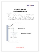
Blending Assembly and Related Parts (See Figure 3)
ITEM PART NO. DESCRIPTION QTY. FUNCTION
1
FCB 112
MODIFIED DOOR SPOUT
ASSEMBLY
1 Dispenses product mixed with flavorings.
1A
RUB 652-RSS
SMALLER SYRUP PORT O-RING 1 ea.
Provides a sealed cavity inside the syrup
port.
1B
RUB 660 LARGER SYRUP PORT O-RING 1 ea.
Provides a sealed cavity inside the syrup
port.
2
ELE 530JBT
SPIGOT SWITCH ASSEMBLY KIT
FOR JUMBO TOUCH PANEL
SYSTEM
1 Activates the syrup pumps.
2A
FAS 2042 4/40 LOCK NUTS 04NK 1 ea. Secures the actuator assembly.
2B
MIS 3180 FCB MAGNET ACTUATOR W/ HOLE 1 ea. Activates the Spigot Switch.
2C
FAS 2140 4-40 x 5/8" PHILLIPS PH S.S. BOLT 1 ea. Secures the actuator to the spout handle.
3
FCB 121 FLOW RATE CONTROLLER 1
Regulates the rate at which product is
dispensed.
3A
FAS 2134 8-32 x 1 ½” M/SCREW P.H. SS 1 ea.
Adjusts to shorten and lengthen the
assembly to allow more or less product
dispensed.
3B
FCB 115 8-32 X 1” PLAS STAND OFF 1 ea. Connects the two screws of the assembly.
3C
FAS 2024 8-32 X ¼” M/SCREW P.H. SS 1 ea. Remains as a stationary screw.
4
SYR 932-
B
9-TUBE ASSEMBLY 1
Supplies syrup to the draw spout from the
pumps.
5
INJ 117 TUBE CONNECTOR BODY-BLACK 1 Secures flavor line manifold to flavor lines.
6
MIS 3142 FLAVOR LINE DUST CAP- FB 80 1 Covers syrup manifold when not connected.
7
INJ 201A SYRUP MANIFOLD 1 Connects flavor line to modified door spout.
8
RUB 601 9-POS DUCKBILLE CHECK VALVE 1
Provides sealed cavity and prevents syrup
leakage.
9 SYR 932
6’ 9-TUBE ASSEMBLY 1
Supplies syrup to the draw spout from the
pumps.
9A
FAS 2051 ROLLED FLANGE EYELET 18 ea
Provides tension in syrup line to affix to line
coupler.
9B
ROT 510 LINE COUPLER 2 ea. Holds flavor lines in place.
9C
RUB 610 BAG CONNECTOR O-RING 1 ea.
Provides extra tension between tube
connectors.
9D
ROT 515-A 9-TUBE ASSEMBLY WAVE SPRING 1 ea. Provides tension between tube connectors.
9E
INJ 116 LINE COUPLER NUT – BLACK 1 ea.
Connects flavor lines to the internal 9-Tube
Assembly.
9F
SYR 901 6’ 9-TUBE ASSEMBLY TUBES 9 ea.
Brings syrup from pump to modified door
spout.
9G
ROT 511 LINE COUPLER NUT 1 ea.
Connects the flavor lines to the internal 9-
Tube Assembly.
9H
RUB 602 9-POS TUBE CONNECTOR GASKET 1 ea. Provides a sealed cavity.

12
Blending Assembly and Related Parts (Continued)
ITEM PART NO. DESCRIPTION QTY. FUNCTION
10
MIS 3196
STAINLESS 9-TUBE CASING
ASSEMBLY
1
Protects and holds the cables and 9-Tube
Assembly in place on the freezer side panel.
10A
MIS 3190
STAINLESS 9-TUBE CASING
HINGED CHANNEL
1 ea.
Covers and protects the cables and tubes of
the Casing Assembly.
10B
MIS 3051
CH-6 CHANNEL MAGNET
ASSEMBLY
2 ea. Holds the Casing Channel to the freezer panel.
10C
FAS 2040 6-32 x 1/4 PAN HEAD SCREW 1 ea.
Secures the Casing cover to the mounting
brackets.
10D
FAS 2024 8-32 x 1/4 PAN HEAD SCREW 4 ea.
Secures the magnet assembly to the mounting
brackets.
10E
FAS 2035 8-32 NUTS-EXT. LOCK WASHER 4 ea.
Secures the magnet assembly to the mounting
brackets.
Figure 3
9H
9
9B
9G
9E
9D
9B
9F
3A
3B
3C
2C
2B
2A
9A
9A
9C
5
4
2
6
7
8
26003
1
3
1B
1A
10
10C
10B
10A
10D
10E

13
Syrup Pump and Related Parts (See Figure 4)
ITEM PART NO. DESCRIPTION QTY. FUNCTION
1 N/A SHAKE SYRUP PUMP 8
Pumps syrup from flavor bags to flavor
lines.
1A SYR 926 PERISTALTIC SYRUP PUMP 1 ea.
Pumps syrup from flavor bags into flavor
lines.
1B TUB 809
1/4" SYRUP SHAKE PUMP
REPLACEMENT TUBE
1 ea. Transports syrup through pump.
1C FIX 1045 1/4" TUBE TO 1/4" HOSE STEM 2 ea.
Creates tension for tighter fit, connects
pump to fitment.
1D FIX 1035
1/4 TO 3/16 OD REDUCING
UNION
1 ea. Connects syrup pump to flavor line out.
1E FIX 1036 1/4" TO 1/4" OD UNION ELBOW 1 ea.
Connects bag connector assembly to
flavor line/pump.
2
SYR 944SH
SYRUP TUBE ASSEMBLY –
SHAKE BAG COUPLER
8
Transports the flavoring from the syrup
bag to the syrup pump.
2A SYR 928 #27-1102-99 .265" BAG COUPLER 1 ea. Fastens bag fitment to bag connector.
2B TUB 811
TUBE-SILICONE .188X.375 PE
FB80
1 ea. Provides sealed cavity inside bag fitment.
2C FIX 1048 FITTING ¼ X ¼ BARB FB80 1 ea.
Connects bag coupler assembly to flavor
line/pump.
2D SYR 902 FLAVOR-IN TUBE 1 ea. Carries syrup from syrup bag to pump.
3 FAS 2051 ROLLED FLANGE EYELET 9
Creates tension for tighter fit, 9 per Tube
Assembly.
4 MIS 3023 DUST CAP 1 Cover to protect end of flavor lines.
5 CAB 113 FLAVORING TRAY 8 Houses syrup bags.
6 ELE 932
PUMP & SANITIZER CABLE
HARNESS
1
Provides power to the syrup and sanitizer
pumps.
7 SYR 900 4' 9-TUBE ASSEMBLY TUBES 9
Brings syrup from pump to Blending
Head.
8 ROT 511 LINE COUPLER NUT 1
Connects flavor lines to the internal 9-
Tube Assembly.
9 ROT 512 TUBE CONNECTOR BODY 1
Connects internal 9-Tube Assembly to
flavor lines.
10 ROT 510 LINE COUPLER 1 Holds flavor lines in place.

14
Syrup Pump and Related Parts
Figure 4
6
7
5
8
9
10
4
3
26004
1
1D
1C
1A
1E
1B
2
2B
2A
2D
2C

15
Sanitizer Pump and Related Parts (See Figure 5)
ITEM PART NO. DESCRIPTION QTY. FUNCTION
1
SAN 748 SANITIZER PUMP ASSEMBLY 1 Supplies sanitizer to flush tube.
2
TUB 807 SANITIZER TUBE REPLACEMENT 1 Transports sanitizer through pump.
3
MIS 3023 DUST CAP 1 Cover to protect end of flavor lines.
4
FAS 2051 ROLLED FLANGE EYELET 1
Creates tension for tighter fit 1 per
pump, 9 per tube assembly.
5
ROT 510 LINE COUPLER 1 Holds flavor lines in place.
6
ROT 512 TUBE CONNECTOR BODY 1
Connects internal 9-Tube Assembly to
flavor lines.
7
ROT 511 LINE COUPLER NUT 1
Connects flavor lines to the internal
9-Tube Assembly.
8
SYR 900 4' 9-TUBE ASSEMBLY TUBES 9
Transports syrup and sanitizer from
pumps to the door spout.
9
FIX 1035 1/4 TO 3/16 OD REDUCING UNION 1 Connects elbow to sanitizer line.
10
FIX 1042 TUBE-TO-TUBE ELBOW 2 Connects pump tube to reducing union.
11
ELE 932
PUMP & SANITIZER CABLE
HARNESS
1
Provides power to the syrup and sanitizer
pumps.
12
SAN 701 SANITIZER TANK 1 Holds sanitizer solution.
13
MIS 3028-S FLUSH TUBE ASSEMBLY - SHAKE 1
Connects with flavor line to flush with
sanitizer solution.
14
FIX 1023 3/16" X 3/16" BARB TUBE CONNECT 1 Splices together flush tubes.
15
TUB 803 .17 x 1/4 LDPE TUBING-PER FOOT 1
Transports sanitizer solution from tank
to sanitizer pump.
16
FIX 1036 1/4" TO 1/4" OD UNION ELBOW 1 Connects sanitizer tube to supply tube.
17
SAN 715 SUPPLY TUBE CAP 1 Fastens grommet securely to tank.
18
RUB 615 FEEDER TUBE RUBBER GROMMET 1
Holds sanitizer tube in place and seals
tank hole.
19
SYR 902 SANITIZER SUPPLY TUBING 1 Supplies sanitizer from Sanitizer Tank.
20
SAN 734
HAND PUMP ASSEMBLY-FLUTED
TANK
1
Seals Sanitizer Tank and adds pressure
when needed.
21
SAN 701 SANITIZER TANK 1 Holds sanitizer solution.
22
FIX 1045 1/4" TUBE TO 1/4" HOSE STEM 1
Connects the Pump Flush Adapter tubing to
the cabinet base fitment.
23
SYR 931 CLEAR TUBING 1
Transports sanitizer solution from tank
to the Pump Flush Adapter.
24
FIX 1033
1/4" X 1/4" BLKHD (PUSH-TO-
CONNECT)
1
Connects Sanitizer Tank tube and neutral
base flush line to the unit.

16
Sanitizer Pump and Related Parts
Figure 5
8
3
4
5
6
7
18
17
16
26005
1
2
10
9
15
23
14
21
13
19
20
Sanitizer Tank
Assembly is
much larger in
scale than
shown here
11
24
22
10

17
Cabinet Electronics (See Figure 6)
ITEM PART NO. DESCRIPTION QTY. FUNCTION
1
ELE 925 RJ45 EHTERNET CABLE -EXTERNAL 1
Connects the Jumbo Touch Panel to the
cabinet.
2
MIS 3026S
JUMBO TOUCH PANEL CABLE
CASING
1
Conceals and protects the Jumbo Touch
Panel cable, as well as attaches it to the
freezer.
3
ELE 926 RJ45 ETHERNET CABLE - INTERNAL 1
Connects the Ethernet cable to the
electronics board.
4
ELE 927 RJ45 ETHERNET CABLE GLAND 1 Secures the Ethernet cable to the cabinet.
5
MIS 3216 CLOSURE PLUG 5/8 INCH 2 Closes up extra opening in the base panel.
6
CAB 137-A ELECTRONICS COVER 1 Protects electronics microprocessor.
7
FAS 2014 8-32 X 1/2" PAN HEAD 16 Secures various parts within the top of unit.
8
MIS 3150 FLAVOR BURST LOGO DECALS 1 Displays Flavor Burst trademark logo.
9
CAB 156 CONNECTOR SHIELD 1 Protects power cables from liquids.
10
ELE 485JB
120V POWER ENTRANCE MODULE 1
Provides a power connection to the outside
of the cabinet.
11
ELE 932
PUMP & SANITIZER CABLE
HARNESS
1 Provides power to syrup & sanitizer pumps.
12
ELE 933 POWER SUPPLY JUMPER CABLE 1 Connects power supply to electronics board.
13
CAB 138TS ELECTRONICS BASE PANEL 1 Secures electronics board.
14
ELE 930
INTERNAL ROTOR CABLE
1
Connects the electronics board to the Auto
Draw Valve Kit (optional).
15
ELE 911 ELECTRONICS BOARD 1 Provides power to the system.
16
FAS 2024 8-32 X 1/4 PAN HEAD SCREW 3 Secures power supply to the base panel.
17
FAS 2035 8-32 NUTS - EXT. LOCK WASHER 3
Secures ground wire to screw and
Panel and the Electronics Box to the panel.
18
FAS 2175 M3.5 NUT - EXT. LOCK WASHER 1
Secures the power entrance module ground
wire to the board.
19
FAS 2008 4-40 X 3/8" PAN HEAD SCREW 4 Attaches the ethernet plate to the panel.
20
FAS 2042 4/40 LOCK NUT 4 Secures the Ethernet plate and screws.
21
MIS 3004
JB ETHERNET CABLE PLATE
1
Converts the touchscreen cable hole to an
ethernet cable hole.

18
Cabinet Electronics
Figure 6

19
2B / 3B Jumbo Touch Panel Electronics (See Figure 7)
ITEM PART NO. DESCRIPTION QTY. FUNCTION
1
MIS 3300A
MAIN JUMBO TOUCH PANEL
FRAME
1
Houses the Jumbo Touch Panel screen and
electronics.
2
MIS 3300B
JUMBO TOUCH PANEL BACK
PANEL
1
Secures the Jumbo Touch Panel to the
freezer.
3
FAS 2008 4-40 X 3/8 PAN HEAD SCREW 2 Fastens the USB mount to the frame.
4
MIS 3300D JBT BACK FRAME MOUNT 4 Allows back panel to be mounted to frame.
5
ELE 950 JBT SCREEN KIT 1
Displays the Jumbo Touch Panel touch
program.
5A
N/A JBT SCREEN & GLASS ASMBY 1 ea. Displays the Jumbo Touch Panel program.
5B
ELE 951
JBT CONTROLLER BOARD & WIRE
SET
1 ea. Electronic components of the Jumbo Touch
Panel screen.
6
MIS 3301 JUMBO TOUCH PANEL HINGE 3
Allows the Jumbo Touch Panel to tilt up for
access to freezer controls.
7
MIS 3191 OPEN-CLOSE BUSHING 1
Protects the Jumbo Touch Panel power
cable.
8
ELE 434JBT EXTERNAL POWER CORD 1
Connects the power supply to the Jumbo
Touch Panel
9
FAS 2065 10-32 NUT 22 Secures various screws within the panel.
10
ELE 966 POWER SWITCH 1
Control to turn Jumbo Touch Panel on and
off.
11
ELE 927 RJ45 ETHERNET CABLE GLAND 2 Secures the Ethernet cable to the cabinet.
12
MIS 3300G JBT INPUT DISPLAY PANEL 1 Covers access to the display panel input.
13
FAS 2064 10-32 X 3/8 PAN HEAD SCREW 16
Holds Jumbo Touch Panel frame and parts
together.
14
MIS 3300E JBT SCREEN BRACKET 2
Connects the Internal Frame Mount to the
sides of the Jumbo Touch Panel frame.
15
ELE 817 MICRO SD CARD 1 Stores information.
16 ELE 953 USB WIFI MBPS 1 Wi-Fi connector.
17
N/A LED STRIP 1
Gives off light to show Jumbo Touch Panel is
powered on.
18
ELE 925 INTERNAL ETHERNET CABLE 1
Connects the external ethernet cable to the
electronics board.
19
ELE 965 SWITCH POWER WIRE 1
Connects the external power switch to the
electronics board.
20
ELE 964 DUAL INLINE SWITCH WIRE 2
Connects the spout switch(es) to the
electronics board.
21
ELE 963 INTERNAL POWER CORD 3-WAY 1
Supplies power to the electronics boards and
LED strip.
22
ELE 954 EXTERNAL USB MOUNT 1
Allows external USB to upload information to
the Jumbo Touch Panel.
/