Page is loading ...

DP/N: 4809662 v1.0 01/13/2010
Owner’s Installation Guide for the
Paxton Automotive
Novi 1500 Supercharger
for the
Universal Big Block
Mopar/440 Carbureted System*
*Legal in California only for racing vehicles which may never be used upon a highway.
Paxton Automotive . 1300 Beacon Place . Oxnard CA 93033
805 487-3796 • FAX (805) 247-0669
SUPERCHARGERS

ii
P/N: 4809662
©2009 Paxton Automotive
All Rights Reserved, Intl. Copr. Secured
13JAN10 v1.0
© 2010 PAXTON AUTOMOTIVE
All rights reserved. No part of this publication may be reproduced, transmitted, transcrived, or translated into another language in any form,
by any means without written permission of Paxton Automotive.
NOTES
• The crank pulley supplied with this kit is designed to accomodate the stock
water pump pulley, alternator and power steering. Vehicles with different
accessories may need custom spacing or elimination of some accessories.
• Duetothemanypossibleengineconfigurationsandboostrequirements,a
standard supercharger pulley has been included in this kit.
FOREWORD
Take note of the following before proceeding:
1.Properinstallationofthissuperchargerkitrequiresgeneralautomotivemechanic
knowledge and experience. Please browse through each step of this instruction
manual prior to beginning the installation to determine if you should refer the job
to a professional installer/technician. Please contact your dealer or Paxton
Automotive for possible installers in your area.
2. This product was designed for use on stock (un-modified, OEM) vehicles. The PCM (com-
puter), engine, transmission, drive axle ratios and tire O.D. must be stock. If the vehicle or
engine has been modified in any way, check with Paxton prior to installation and use of this
product.
3. Use only premium grade fuel with a minimum of 91 octane (R+M/2).
4. Always listen for any sign of detonation (knocking/pinging) and discontinue hard use (no boost)
until the problem is resolved.
5. Paxton is not responsible for any clutch, transmission, drive-line or engine damage.
Exclusions from Paxton warranty coverage considerations include, but
not limited to:
1. Neglect, abuse, lack of maintenance, abnormal operation or improper installation.
2. Continued operation with an impaired vehicle or sub-system.
3. The combined use of Paxton components with other modifications such as, but not limited to,
exhaust headers, aftermarket camshafts, nitrous oxide, third party PCM programming or other
such changes.
This manual provides information on the installation, maintenance and service of the Paxton
supercharger kit expressly designed for this vehicle. All information, illustrations and specifi-
cations contained herein are based on the latest product information available at the time of
this publication. Changes to the manual may be made at any time without notice. Contact Paxton
Automotive for any additional information regarding this kit and any of these modifications at (805)
888-PAXTON 8:00am-4:30pm PST.

iii
P/N: 4809662
©2009 Paxton Automotive
All Rights Reserved, Intl. Copr. Secured
13JAN10 v1.0
***IMPORTANT NOTES ***
The following carbureted base system support parts are not included as part of the system but are
available from Paxton Automotive:
1. Carburetor enclosure P/N: 8PM205-060/068
Optional fuel line/fittings kits for the carburetor. They include custom bent stainless steel lines, billet -8 bulk-
head adapter with fuel pressure port and plug, -8/-6 junction TEE, aluminum swivel hose ends and USCG
approved fuel hose.
•Paxton#8M110-020 Holley 4150 series (w/dual metering blocks), SS fuel line kit.
•Paxton#8M110-030 Demon series, SS fuel line kit.
2. Carburetor air diffuser, straightens airflow into the carburetor for improved response/driveability.
•Paxton#8M011-001 Ø5.75" x 2.50" tall carburetor air diffuser, stainless steel.
3. RaceBypassP/N8D204-010isincludedinthe1201860(P)systemsandisrequiredforapplicationsexceed-
ing5psi.Alargercompressorbypassvalveandflangeisrequiredonapplicationsexceeding10psigboost/
600HP. Contact the technical department to determine the proper valve selection for the application.
•Paxton#8D103-001 Mondo Race Bypass Valve
•Paxton#8D003-052 Mondo Race Bypass Valve weld-on flange (aluminum)
•Paxton#9AT200-090 Tube, aluminum Ø2.0" x specify length (for welding 8D004-052 to round tube)
•Paxton#8D205-003 BV57 Bypass Valve (Includes V-Band Clamp and O-ring Seal)
•Paxton#8D005-051 BV57 Bypass Valve weld-on flange (aluminum)
4. Boost referenced ignition/timing retard systems.
•Paxton#5A001-009 HI-6 TR Ignition System “CRANE”
•Paxton#5A001-001 Stand alone ignition retard “MSD” (not an ignition enhancer)
5. Supercharger pulleys: (Contact technical department for proper appication match)
•Paxton#4MA031-312: 3.12" Diameter 10-rib driven pulley
•Paxton#4MA031-333: 3.33" Diameter 10-rib driven pulley
•Paxton#4MA031-347: 3.47" Diameter 10-rib driven pulley
•Paxton#4MA031-360: 3.60" Diameter 10-rib driven pulley
•Paxton#4MA018-051: 7.00" Diameter 10-rib drive (crank) pulley
•Paxton#4MA018-061: 7.80" Diameter 10-rib drive (crank) pulley
Items to be supplied by installer/end user:
•Carburetorwithmechanicalsecondaries(4150Holley/BarryGrantMDstyle)
•Highperformanceelectricfuelpump
•Boostreferencedfuelpressureregulator

iv
P/N: 4809662
©2009 Paxton Automotive
All Rights Reserved, Intl. Copr. Secured
13JAN10 v1.0
This Page Left Intentionally Blank

v
P/N: 4809662
©2009 Paxton Automotive
All Rights Reserved, Intl. Copr. Secured
13JAN10 v1.0
TABLE OF CONTENTS
FOREWORD . . . . . . . . . . . . . . . . . . . . . . . . . . . . . . . . . . . . . . . . . . . . . . . . . . . . . . . . . . . . . . . . . . . . . . ii
CARBURETED BASE SYSTEM SUPPORT PARTS .....................................iii
TABLE OF CONTENTS..............................................................v
TOOL & SUPPLY REQUIREMENTS ................................................. vi
PARTS LIST (Big Block Mopar 440 - 1201860-1) ........................................vii
PARTS LIST (Big Block Mopar 440 - 1201860) ..........................................viii
1. INTRODUCTION ............................................................ 1
2. PREPARATION/REMOVAL .................................................... 3
3. OIL FEED INSTALLATION ....................................................51
4. OIL DRAIN INSTALLATION................................................... 7
5. MOUNTING BRACKET/SUPERCHARGER INSTALLATION........................ 9
6. CRANK PULLEY INSTALLATION..............................................15
7. AIR INLET DUCTING INSTALLATION .........................................17
8. CARBURETOR MODIFICATIONS ..............................................19
9. DISCHARGE INSTALLATION (Option) .........................................21
10. FINAL RE-ASSEMBLY AND CHECK ...........................................23

vi
P/N: 4809662
©2009 Paxton Automotive
All Rights Reserved, Intl. Copr. Secured
13JAN10 v1.0
Universal Big Block Mopar
Carbureted System
Installation Instructions
PLEASE READ CAREFULLY
Thiskitshouldonlybeinstalledbyqualifiedmechanics.It is imperative that the
correct air/fuel mixture be maintained at all times. This kit is to be supplied
to competent engine tuners for their completion by the addition of, and tun-
ing of, an appropriate carburetor unit.
This product is intended for use on healthy, well maintained engines. Installation
on a worn-out or damaged engine is not recommended and may result in failure of
the engine.
Paxton Automotive is not responsible for engine damage. Installation on new
engines will not harm or adversely affect the break-in period so long as factory
break-in procedures are followed.
For best performance and continued durability, please take note of the following key points:
1. Use only premium grade fuel 91 octane or higher (R+M/2).
2. The engine must have stock or lower than stock compression ratio.
3. If the engine has been modified in any way, check with Paxton prior to using this
product.
4. Always listen for any sign of detonation (pinging) and discontinue hard use (no
boost) until problem is resolved.
5. Perform an oil and filter change upon completion of this installation and prior to
operating the vehicle. Thereafter, always use a high grade “SF” rated engine oil or a
highqualitysynthetic,andchangetheoilandfilterevery3000miles.
6. Before beginning installation, replace all spark plugs with one to two step colder heat
range and reset timing to no more than 22° total or install a boost retard ignition.
(Always follow the procedures indicated in the factory repair manual.)
TOOL & SUPPLY REQUIREMENTS:
•FactoryRepairManual
•3/8"DriveandSocketSet:SAEandMetric
•1/2"DriveandSocketSet:SAEandMetric
•OpenEndWrenches:SAEandMetric
•OilDrainTools
•SFRatedQualityEngineOil
•LoctiteSealer#RC-609
•OilFilter,andWrench
•HeavyGrease
•SiliconeSealer
•TeflonPasteSealant
•TAP,3/8-18NPT
S U P E R C H A R G

vii
P/N: 4809662
©2009 Paxton Automotive
All Rights Reserved, Intl. Copr. Secured
13JAN10 v1.0
Part No. DescriPtioN Qty. Part No. DescriPtioN Qty.
IMPORTANT: Before beginning installation, verify that all parts are included in the kit. Report any shortages or damaged parts
immediately.
Big Block Mopar “Tuner” Kit 440
Part No. 1201860-1, 1201860-1P
PARTS LIST
1016143 S/C ASY,NOVI 1500,CW,CRV,10-RI 1
4PCF110-044 MTG BRKT ASSY, 440 BB MOPAR 1
2A017-040 SEPARATOR, BEARING, 6203 1
2A017-875-01 SPACER, .875 OD X 1.315 LONG 2
2A017-875-08 SPACER, .875 OD X .290 LONG 5
2A017-875-19 SPACER, .875 OD, .404 ID X 1.6 1
2A017-875-20 SPACER, .875 OD X .404 ID X 1. 4
4FP116-030 IDLERW/BRNGASSY,36MMCOG 1
4GA017-011 SPCR, IDLR,DL. PLT BBC 10-RIB 1
4PCF010-011 BLK, MOUNTING CYL HEAD, MOPAR 1
4PCF010-034 PLT, DUAL SUPPRT, MOPAR 440 BB 1
4PCF010-044 PLT, SUPERCHARGER MNTNG, MOPAR 1
4PFA010-031 BRACKT,IDLERADJUSTSCREW 1
7A250-100 1/4-20 X 1 FLAT ALLEN 2
7A375-105 3/8-16 X 1" HHCS, GR8, PLATED 2
7A375-151 3/8-16 X 1.5 HXHD GR8 5
7A375-253 3/8-16 X 2.5" HX HD GR8 FULL T 1
7A375-426 3/8-16 X 4.25" HX HD GR8 2
7A375-650 3/8-16 X 6-1/2 HX GR5 3
7B375-200 3/8-24 X 2" GR8 BOLT 3
7B500-240 ARBOR, S/C TENS PLY, RENEGADE 1
7C012-022 M12 X 1.75 X 20MM THIN HD 3
7F375-028 PRESS NUT, 3/8-24 X .50 3
7F500-020 1/2"-20 HEX JAM NUT GR5 ZINC 1
7J012-092 12MMWASHER,FLAT 3
7K375-040 3/8AN960FLATWASHRPLATED 16
7PA375-500 SCREW,IDLERADJUST,5.00" 1
4PCF112-010 AIR INLET ASM, 440 BB MOPAR 1
4PCF012-010 INLET TUBE, MOPAR 440 1
8H040-235 AIR FILTER, 4" FLG X 7.0L 1
7R002-060 #60SAETYPEFSSHOSECLAMPS 1
7R002-064 #64SAETYPEFSSHOSECLAMP 1
7PS400-375 SLEEVE 4.0 X 3.75 X 3.0L 1
4PCF116-010 DRIVE ASSY, 10-RIB- 440 BB MOP 1
2A041-594 BELT, K100594-GATES 1
4PCF017-011 SPCR, CRNK PULY MOPAR 440 1
4MA018-041 CRANK PLY, 6", UNIVERSAL 1
7A312-375 5/16-18 X 3 3/4"SHCS 6
7A312-152 5/16-18 X 1.5 SHCS, ZN PLT 6
7K312-001 5/16ANWASHER,PLATED 6
7A312-326 5/16-18 X 3.25 SHCS ZINC CLS 1 6
4PCF130-026 OIL FEED ASSY, 440 BB MOPAR 1
7P125-034 1/8NPTX1/8NPT STRT T 1
7P125-103 1/8NPT X 45° -4SAE FLARE 2
7P125-016 1/8 NPT PLUG 1
7U250-000-420 OIL FEED HOSE,42",-4 STRT 1
4PCF130-036 OIL DRAIN ASSY, 440 BB MOPAR 1
7U030-036 1/2" OIL DRAIN HOSE 4FT
7R001-008 #8STNLSHOSECLAMP 2
7P375-017 3/8NPT X 1/2 BEADED HSE BRB 1
4PCF010-051 PLATE, DRAIN RETURN, FUEL BLOC 1
7A375-076 3/8-16 X 3/4" HXHD S.S. 2
7K375-040 3/8AN960FLATWASHRPLATED 2
4PCF040-050 GASKET, FUEL PUMP PLATE 1
008575 3 YR S/C STRT INFO PKG ASSY PA 1
4809662 INSTR. MANUAL,BB. 440 MOPAR CA 1
OPTIONAL EQUIPMENT
4MA031-275 S/C PULLEY, 2.75" GEN2 MERC 1
4MA031-295 S/C PULLEY, 2.95" GEN2 MERC 1
4MA031-312 S/C DRIVE PULLEY 3.12" GEN2 MERC 1
4MA031-333 S/C DRIVE PULLEY 3.33" GEN2 MERC 1
4MA031-347 S/C DRIVE PULLEY 3.47" GEN2 MERC 1
4MA031-360 S/C DRIVE PULLEY 3.60" GEN2 MERC 1
5A001-008 HI-6 TR IGN. SYSTEM, CRANE 1
SUPERCHARGERS

viii
P/N: 4809662
©2009 Paxton Automotive
All Rights Reserved, Intl. Copr. Secured
13JAN10 v1.0
IMPORTANT: Before beginning installation, verify that all parts are included in the kit. Report any shortages or damaged parts
immediately.
Big Block Mopar “Universal” Kit 440
Part No. 1201860, 1201860-P
PARTS LIST
1016143 S/C ASY,NOVI 1500,CW,CRV,10-RI 1
4PCF110-044 MTG BRKT ASSY, 440 BB MOPAR 1
2A017-040 SEPARATOR, BEARING, 6203 1
2A017-875-01 SPACER, .875 OD X 1.315 LONG 2
2A017-875-08 SPACER, .875 OD X .290 LONG 5
2A017-875-19 SPACER, .875 OD, .404 ID X 1.6 1
2A017-875-20 SPACER, .875 OD X .404 ID X 1. 4
4FP116-030 IDLERW/BRNGASSY,36MMCOG 1
4GA017-011 SPCR, IDLR,DL. PLT BBC 10-RIB 1
4PCF010-011 BLK, MOUNTING CYL HEAD, MOPAR 1
4PCF010-034 PLT, DUAL SUPPRT, MOPAR 440 BB 1
4PCF010-044 PLT, SUPERCHARGER MNTNG, MOPAR 1
4PFA010-031 BRACKT,IDLERADJUSTSCREW 1
7A250-100 1/4-20 X 1 FLAT ALLEN 2
7A375-105 3/8-16 X 1" HHCS, GR8, PLATED 2
7A375-151 3/8-16 X 1.5 HXHD GR8 5
7A375-253 3/8-16 X 2.5" HX HD GR8 FULL T 1
7A375-426 3/8-16 X 4.25" HX HD GR8 2
7A375-650 3/8-16 X 6-1/2 HX GR5 3
7B375-200 3/8-24 X 2" GR8 BOLT 3
7B500-240 ARBOR, S/C TENS PLY, RENEGADE 1
7C012-022 M12 X 1.75 X 20MM THIN HD 3
7F375-028 PRESS NUT, 3/8-24 X .50 3
7F500-020 1/2"-20 HEX JAM NUT GR5 ZINC 1
7J012-092 12MMWASHER,FLAT 3
7K375-040 3/8AN960FLATWASHRPLATED 16
7PA375-500 SCREW,IDLERADJUST,5.00" 1
4PCF112-010 AIR INLET ASM, 440 BB MOPAR 1
4PCF012-010 INLET TUBE, MOPAR 440 1
8H040-235 AIR FILTER, 4" FLG X 7.0L 1
7R002-060 #60SAETYPEFSSHOSECLAMPS 1
7R002-064 #64SAETYPEFSSHOSECLAMP 1
7PS400-375 SLEEVE 4.0 X 3.75 X 3.0L 1
4PCF112-030 AIR DISCHARGE ASM, 440 BB MOPA 1
7PS350-275 SLEEVE, 3.5"-2.75", REDUCER 1
7R002-044 #44SAETYPEFSSHOSECLAMP 1
7R002-056 #56SAETYPEFSSHOSECLAMP 3
7PS350-200 SLEEVE, BLACK 3.50"IDX2.0"LG 1
4GS012-030 ELBOW,3.5ODX73,C6TB,AL 1
8D004-052 FLNG,WELD,RACEBYPASS,ALUM. 1
8D004-055 TUBE,AL,1.5ODX.9WALLX1 1
8M008-011 CARBHAT,BLOWTHRUSATIN 1
8D204-010 RACE BYPASS VALVE-BLACK 1
4PCF116-010 DRIVE ASSY, 10-RIB- 440 BB MOP 1
2A041-594 BELT, K100594-GATES 1
4PCF017-011 SPCR, CRNK PULY MOPAR 440 1
4MA018-041 CRANK PLY, 6", UNIVERSAL 1
7A312-375 5/16-18 X 3 3/4"SHCS 6
7A312-152 5/16-18 X 1.5 SHCS, ZN PLT 6
7K312-001 5/16ANWASHER,PLATED 6
7A312-326 5/16-18 X 3.25 SHCS ZINC CLS 1 6
4PCF130-026 OIL FEED ASSY, 440 BB MOPAR 1
7P125-034 1/8NPTX1/8NPT STRT T 1
7P125-103 1/8NPT X 45° -4SAE FLARE 2
7P125-016 1/8 NPT PLUG 1
7U250-000-420 OIL FEED HOSE,42",-4 STRT 1
4PCF130-036 OIL DRAIN ASSY, 440 BB MOPAR 1
7U030-036 1/2" OIL DRAIN HOSE 4FT
7R001-008 #8STNLSHOSECLAMP 2
7P375-017 3/8NPT X 1/2 BEADED HSE BRB 1
4PCF010-051 PLATE, DRAIN RETURN, FUEL BLOC 1
7A375-076 3/8-16 X 3/4" HXHD S.S. 2
7K375-040 3/8AN960FLATWASHRPLATED 2
4PCF040-050 GASKET, FUEL PUMP PLATE 1
008575 3 YR S/C STRT INFO PKG ASSY PA 1
4809662 INSTR. MANUAL,BB. 440 MOPAR CA 1
OPTIONAL EQUIPMENT
4MA031-275 S/C PULLEY, 2.75" GEN2 MERC 1
4MA031-295 S/C PULLEY, 2.95" GEN2 MERC 1
4MA031-312 S/C DRIVE PULLEY 3.12" GEN2 MERC 1
4MA031-333 S/C DRIVE PULLEY 3.33" GEN2 MERC 1
4MA031-347 S/C DRIVE PULLEY 3.47" GEN2 MERC 1
4MA031-360 S/C DRIVE PULLEY 3.60" GEN2 MERC 1
5A001-008 HI-6 TR IGN. SYSTEM, CRANE 1
SUPERCHARGERS
Part No. DescriPtioN Qty. Part No. DescriPtioN Qty.

1
P/N: 4809662
©2009 Paxton Automotive
All Rights Reserved, Intl. Copr. Secured
13JAN10 v1.0
Section 1
INTRODUCTION
Congratulations! You have purchased the fin-
est street Supercharger available. The center-
piece of this kit is the highly efficient and
reliable Paxton Automotive Corp. NOVI-1500
supercharger. A mechanically driven (by belt) cen-
trifugal blower (supercharger).
This kit comes with all of the parts you’ll need for
asuccessfulinstallation.Theoperationsrequired
havebeengroupedinorderofsequence.Photos
anddrawingsaccompanythetext,allowingquick
orientation and parts identification.
Installationrequiresaselectionoftoolswhichare
listed on page vi.
Wealsosuggestthatyouobtainashopmanualand
become familiar with the details of your cars sys-
tems.
For best results follow the instructions closely and
insequence.Theaverageinstallationtimeforthis
kit is 6 hours. Your actual installation time will
depend on skill level and working conditions. The
estimate does not include time for initial vehicle
inspection, cleaning, fine tuning or troubleshooting.
Before even picking up a wrench, read this entire
manual.Weareavailablefortechnicalassistanceat
(805) 487-3796, 8am-4:30pm pacific time.
After reading the manual, verify that all major
assembly groups are present in the main kit box.
You should have ample space to layout the compo-
nents. As you remove a box or bag from the main
kit, note the identification label and compare it
with the parts list. Please check the box for small
parts.
Paxton makes every effort to insure that all parts
are included in the box. However, if you discover
any missing or mislabeled parts, please contact
Paxton by phone for service.
***WARNING***
DO NOT attempt installation if any part(s) are missing
from this kit. Failure to contact Paxton prior to beginning
installation will result in a charge for any missing parts.
Before starting the installation, we suggest your
engine compartment be clean. You can clean the
engine and compartment with a pressure washer
(such as those used at self serve car washes) and a
safe-for-aluminum cleaner/degreaser. Cover the
distributor with a plastic bag to prevent water from
entering.
*** CAUTION ***
Wedonotrecommendproceedingwiththekitinstallation
unless your vehicle is within normal operating parame-
ters.
You are undoubtedly enthusiastic about getting
started on your project, but take just a little more
time to insure that your safety is not jeopardized. A
moment’s lack of attention can result in an acci-
dent, as can failure to observe certain simple safety
precautions. The possibility of an accident will
always exist, and the following points should not
be considered a comprehensive list of all dangers.
Rather, they are intended to make you aware of the
risk and to encourage a safety conscious approach
to all work you do on your vehicle.
Welookforwardtohearingfromyou,particularly
if you have any comments or suggestions regarding
this manual at:
(805) 487-3796
Paxton Automotive Corporation
1300 Beacon Place
Oxnard, CA 93033
E-mail Address [email protected].
*** NOTE ***
Throughout these procedures the word “discard” is used
periodically in relationship to items that will no longer be
utilized in conjunction with the supercharger installation.
It is recommended that these items be saved for future use
should it become necessary.

2
P/N: 4809662
©2009 Paxton Automotive
All Rights Reserved, Intl. Copr. Secured
13JAN10 v1.0
• Neverrelysolelyonajackwhenworkingunderavehicle.Alwaysusean
approved set of jackstands to support the vehicle and place them under the rec-
ommended lift points.
• Whenjackingavehicle,makesureitisonalevelsurface,preferablyconcreteor
asphalt. The transmission should be in “PARK” or “FIRST”, the parking brake
engaged and the wheels blocked.
• Neverstartthecarwithoutfirstverifyingthatthetransmissionisinneutraland
the parking brake is set.
• Neverremovetheradiatorcapwhiletheengineishot.
• Alwaysweareyeprotectionwhenusingpowertoolssuchasdrills,saws,grind-
ers, etc., or when working under a vehicle.
• Neversmoke,useanopenflame,orhavespark-producingitemsaroundgasoline
or flammable solvents. Always have a fire extinguisher rated for chemical and
electrical fires handy when working on motor vehicles.
• Runenginesonlyinwellventilatedareas.Carbonmonoxide,gasoline,andsol-
vent vapors are colorless and sometimes odorless. These can asphyxiate or
explode without warning.
• Alwaysdisconnectatleastthenegative(-)orgroundterminalofthebatterywhen
doing any electrical, fuel system, or underdash work.
Paxton Automotive makes every effort to insure that all parts are included in the box, but
mistakes do occur. If you discover that you are missing any part, or that a part is damaged in
transit, please call Paxton Automotive for service. DO NOT attempt installation if any part(s)
are missing from this kit. Failure to contact Paxton prior to beginning installation will result
inachargeforanymissingparts.Welookforwardtohearingfromyou,particularlyifyou
have any comments or suggestions regarding this manual.
WARNINGS

3
P/N: 4809662
©2009 Paxton Automotive
All Rights Reserved, Intl. Copr. Secured
13JAN10 v1.0
Section 2
PREPARATION/REMOVAL
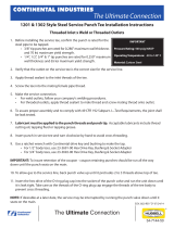
2.1 PREPARATION/REMOVAL
A. Disconnect the negative lead of all batteries.
*** NOTE ***
Refer to Fig. 2.1-a for the following steps.
B. Loosen all nuts and bolts that are used to ten-
sion the alternator and power steering pump
V-belts.
C. Remove all of the belts from the accessories.
D. Remove the stock crank pulley.
E. Remove the alternator stay (adjustment bar) and
retain hardware to be reused in a later step.
*** NOTE ***
If you have not changed spark plugs in the last 15,000
miles, do so prior to the installation of this kit.
Fig. 2.1-a
FACTORY
ALTERNATOR
BRACKET
FACTORY
CRANK PULLEY
ALTERNATOR
STAY
F. Remove any remaining hardware securing
the alternator to the cylinder head. The alter-
nator will be relocated in a lower position.
*** NOTE ***
If you are installing a universal supercharger kit,
some of the following instructions may not apply or
mayrequirecustomfabrication.
*** NOTE ***
Thecurrentsetupofthiskitrequirestheuseofthe
following components:
- Electric radiator coling fan(s).
- Stock crank & accessory pulleys
- Electric fuel pump with boost referenced regulator
- Appropriate carburetor

4
P/N: 4809662
©2009 Paxton Automotive
All Rights Reserved, Intl. Copr. Secured
13JAN10 v1.0
This Page Left Intentionally Blank

5
P/N: 4809662
©2009 Paxton Automotive
All Rights Reserved, Intl. Copr. Secured
13JAN10 v1.0
Section 3
OIL FEED INSTALLATION
A. The supercharger uses engine oil for lubrica-
tion and must have an oil feed line connect-
ed to a filtered oil access on the engine.
B. Install the supplied 1/4"NPT street TEE into
the block located on upper rear of the engine
block just above where the bell housing
attaches. Install the oil pressure sender into
the end of the TEE. Install the 1/4" x -4 fit-
ting into the branch of the TEE. Position the
fitting so that the opening faces the passen-
ger’s side/rear of the engine. (See Fig. 3.1-
a.)
*** NOTE ***
Use clean engine oil on the pipe threads. Teflon tape
and sealant is NOT recommended as it might loosen
and cause blockage of the small oil feed orifice
resulting in supercharger failure.
C. Attach the end of the supplied -4 braided oil
feed line to the installed fitting. (See Fig.
3.1-a.) Secure the hose with the tie-wraps
provided, routing it away from exhaust heat,
chafing and/or sharp objects. Temporarily
cover the open end from debris until the
connection is made to the supercharger.
3.1 OIL FEED INSTALLATION
Fig 3.1-a.

6
P/N: 4809662
©2009 Paxton Automotive
All Rights Reserved, Intl. Copr. Secured
13JAN10 v1.0
This Page Left Intentionally Blank

7
P/N: 4809662
©2009 Paxton Automotive
All Rights Reserved, Intl. Copr. Secured
13JAN10 v1.0
Section 4
OIL DRAIN INSTALLATION
4.1 OIL DRAIN INSTALLATION (OPTION 1)
A. To provide an oil drain for the supercharger,
it is necessary to install the supplied
mechanical fuel pump block off plate with
barb fitting.
B. Install the plate and gasket using two sup-
plied 3/8-16 x .75” bolts and washers onto
the port located on the front passenger side
of the block, just behind the water pump.
Fig. 4.2-a
C. Attach one end of the ½” drain line to the
barb end of the installed fitting and secure
with#8hoseclamp.Routethehoseup
towards the passenger side of the car to be
connected to the supercharger in a later step.
1"
.75"
PUNCH HOLE THROUGH
Fig. 4.2-a
Passenger side oil drain
4.2 OIL DRAIN INSTALLATION (OPTION 2)
A. Alternately, you can punch a hole in the side
of the oil pan. The hole should be placed
above the oil level in the pan to allow for
unrestricted flow of the return oil. (Roughly
no more than 1’” below the top edge of the
pan)
*** NOTE ***
Removal of the oil pan may ease oil drain fitting
installation on some applications.
B. Remove any paint from around the hole area.
C. Use a small center punch to perforate the pan
and expand the hole, switch to a larger diam-
eter punch and expand the hole further to
approximately Ø9/16". Most punches are
made from hexagon material and may be
placed in a socket with an extension to make
this procedure easier. Use caution so that the
hole is not enlarged too much and that the
punch does NOT contact the engine inter-
nals.
D. Tap the hole with a 3/8"NPT tap approxi-
mately 1/4" deep. Pack the flutes of the tap
with heavy grease to hold the chips. Use a
small magnet to check for any stray chips.
Fig. 4.2-a
*** NOTE ***
This method of rolling over the lip of the hole and
tapping works very well if carefully done and should
cause no problems.
E. Thoroughly clean the threaded area. Apply a
small amount of silicone sealer to the new
threads. Apply more sealer to the supplied
3/8"NPT x 1/2" barb, and secure in the previ-
ously threaded hole. Make sure a seal is
formed all around the fitting.
F. Drain the engine oil, install a new filter and
refill with fresh oil.
Fig. 4.1-a

8
P/N: 4809662
©2009 Paxton Automotive
All Rights Reserved, Intl. Copr. Secured
13JAN10 v1.0
This Page Left Intentionally Blank

9
P/N: 4809662
©2009 Paxton Automotive
All Rights Reserved, Intl. Copr. Secured
13JAN10 v1.0
Section 5
MOUNTING BRACKET/SUPERCHARGER
INSTALLATION
5.1 MOUNTING BRACKET INSTALLATION
A. Clean the front of the passenger’s side cylin-
der head so that the mounting spacers will sit
flat when installed.
B. Clean the front of the water pump bosses so
the supercharger bracket will mount flat
against the mounting surfaces.
*** NOTE ***
Refer to Fig. 5.1-b for assistance in the next few
steps. DO NOT tighten hardware until all fasteners
and spacers are installed.
C. Locate the mounting bracket assembly
D. Locate the three 3/8-16x 6.5” bolts, 3/8 AN
washers, cylinder head mounting block,
1.691” spacer, and main supercharger mount-
ing bracket (See Fig. 5.1-a.)
E. Install two of the 6.5” bolts and washers
through the main bracket and then through
the cylinder head mounting block as shown
in Figs 5.1-b, 5.1-c Make sure the side of
the mounting block with the center tapped
hole faces the rear side of the Main Bracket.
Fig. 5.1-a
Fig. 5.1-b
Fig. 5.1-c

10
P/N: 4809662
©2009 Paxton Automotive
All Rights Reserved, Intl. Copr. Secured
13JAN10 v1.0
F. Attach the factory alternator using the third 6.5” bolt and washer through the lower hole
of the main bracket, next through the alternator, then through the 1.691” spacer and final-
ly into the cylinder head. Keep the bolt loose until the belt is tensioned in a later step.
(See Fig. 5.1-d.)
G. Locate two 3/8-16x 1.0” bolts and 3/8 AN washers and install through the two holes locat-
ed in the tail end of the main supercharger mounting bracket and into the threaded water
pump bosses. (See Fig 5.1-d)
H. Locate two 3/8-16x 4.25” bolts, 3/8 AN washers, and two 1.315” spacers. Install one bolt
& washer through the hole located in the recessed section of the main bracket, then through
one of the 1.315” spacers, through the water pump and finally into the engine block. (See
Fig 5.1-d). Install the second bolt and washer through the factory alternator stay (adjust-
ment bar), through a 1.315” spacer, through the water pump and into the engine block.
I. Attach the alternator stay to the alternator using the factory retainer.
J. Route the v-belt (not included) around the crank, water pump, and alternator pulleys and
swing the alternator to tension.
K. Tighten all hardware installed to this point, making sure that all spacers and brackets are
flat against their mounting surfaces.
Fig. 5.1-d

11
P/N: 4809662
©2009 Paxton Automotive
All Rights Reserved, Intl. Copr. Secured
13JAN10 v1.0
A. Attach the open end of the oil drain line to the
superchargerandsecureusingoneofthe#8hose
clamps provided.
*** NOTE ***
The oil drain hose may need to be trimmed for prop-
er fit. It must maintain a continuous downward direc-
tion free of any dips or restrictions.
B. Lower the supercharger onto the mounting plate
installed on the engine.
C. Locate the five 3/8-16 x 1.5" bolts, 3/8 AN wash-
ers, and five .29” spacers. Install the five bolts
through to the supercharger while sandwiching
the .29” spacers between the supercharger mount-
ing bosses and the backside of the main bracket.
Tighten in steps. (See Fig 5.2-a.)
D. If not already completed, attach the oil drain line
to the fitting previously installed in the oil pan or
fuel pump block off plate and secure using the
supplied#8hoseclamp.
E. Install the 1/8"NPT x -4 x 45° fitting onto the oil
feed fitting using oil to lubricate the threads.
Attach the oil feed hose to this fitting and tighten.
(See Fig. 5.2-b.)
*** NOTE ***
Some applications (depending on intake manifold
height)mayrequirethereclockingofthesupercharg-
ervolute.Ifreclockingisrequiredforyourapplica-
tion, loosen and remove the six 1/4-20 cap screws
and retaining plates that hold the compressor housing
(volute) to the gearcase. If the compressor housing
does not rotate freely relative to the gearcase, DO
NOT FORCE IT. SERIOUS SUPERCHARGER
DAMAGE MAY OCCUR. The machined mating sur-
faces are designed to prevent pressurized air from
escaping and have minimal tolerances. If the housing
will not move or is very tight, contact Paxton
Automotive immediately at 888 9-PAXTON and ask
our service department for further assistance.
5.2 SUPERCHARGER INSTALLATION
Fig. 5.2-a
Fig. 5.2-b

12
P/N: 4809662
©2009 Paxton Automotive
All Rights Reserved, Intl. Copr. Secured
13JAN10 v1.0
A.. Attach the supplied tensioner adjustment screw, tensioner arbor and adjustment screw locator
block to the back of the tensioner plate using the ¼-20 Flat Head screws as shown in Fig 5.3-a.
*** NOTE ***
Apply a small amount of anti-seize lube to the threads on the tensioner adjustment screw prior to assembly.
B. Assemble the idler pulley pilot spacer, idler pulley with snap ring facing rear of vehicle, pilot
washer, and ½-20 jam nut on to tensioner arbor as shown in Fig. 5.3-a. Assemble parts as
shown, but leave 1/2" nut just loose enough to allow for adjustment with tensioner adjustment
screw. Position idler pulley by adjusting tensioner screw so that access to the hardware mount-
ing holes is not obstructed (in order to allow for installation on to main bracket).
5.3 TENSIONER PLATE INSTALLATION
Fig. 5.3-a
/