
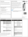
Technical item or function Technical data
Mains connection
Input voltage U
in
208-240V, 380-500V, 525-600V, 525-690V, -10%…+10%
Input frequency 50-60 Hz, -5...+10%
Connection to mains Once per minute or less
Starting delay 6 s (MR4 to MR6), 8 s (MR7 to MR9)
Mains
•
Mains types: TN, TT, and IT
•
Short circuit current: the maximum short circuit
current must be < 100 kA.
Motor connection
Output voltage 0-U
in
Continuous output current
I
L
: Ambient temperature max. +40 °C overload 1.1 x I
L
(1 min/10 min)
I
H
: Ambient temperature max. +50 °C overload 1.5 x I
H
(1 min/10 min)
I
H
in 600/690 V drives: Ambient temperature max. +40
°C overload 1.5 x I
H
(1 min/10 min)
Output frequency 0-320 Hz (standard)
Frequency resolution 0.01 Hz
The technical data of the Vacon
®
100 AC drive
Technical item or function Technical data
Protections
Overvoltage trip limit
Mains voltage 240 V: 456 VDC
Mains voltage 500 V: 911 VDC
Mains voltage 600 V: 1094 VDC
Mains voltage 690 V: 1258 VDC
Undervoltage trip limit Depends on mains voltage (0.8775 x mains voltage):
Mains voltage 240 V: trip limit 211 VDC
Mains voltage 400 V: trip limit 351 VDC
Mains voltage 500 V: trip limit 438 VDC
Mains voltage 525 V: trip limit 461 VDC
Mains voltage 600 V: trip limit 527 VDC
Mains voltage 690 V: trip limit 606 VDC
Earth fault protection Yes
Mains supervision Yes
Motor phase supervision Yes
Overcurrent protection Yes
Unit overtemp. protection Yes
Motor overload protection Yes. * The motor overload protection activates at 110%
of the full load current.
Motor stall protection Yes
Motor underload protection Yes
Short-circuit protection of
+24 V and +10 V reference
voltages
Yes
* = For the motor thermal memory and the memory retention function to obey the UL
61800-5-1 requirements, you must use the system software version FW0072V007 or a newer
version. If you use an older system software version, you must install a motor
overtemperature protection to obey the UL regulations.
VACON
®
100 AC DRIVES
INSTALLATION IN
US AND CANADA
QUICK GUIDE
UL STANDARDS ON CABLING
To obey the UL (Underwriters Laboratories) regulations, use a UL-approved Class 1
copper wire with a minimum heat resistance of 60 or 75 °C (140 or 167 °F).
You can use the drive on a circuit that gives a maximum of 100 000 rms symmetrical
amperes, and a maximum of 600 V, when the drive is protected by Class T and J fuses.
CABLE AND FUSE SIZES, NORTH AMERICA
We recommend the fuse class T (UL & CSA). To make a selection of the fuse voltage
rating, refer to the mains. Refer also to local regulations, cable installation conditions
and cable specification. Do not use larger fuses than what is recommended.
Make sure that the operation time of the fuse is less than 0.4 seconds. The operation
time agrees with the fuse type and the impedance of the supply circuit. For more
information on faster fuses, speak to the manufacturer. The manufacturer can also
recommend some high speed Class J (UL & CSA ) fuse ranges.
The solid state short circuit protection does not supply protection for the branch circuit
of the of the AC drive. To supply the branch circuit protection, refer to the National
Electric Code and the local regulations. Do not use other devices than fuses to supply
branch circuit protection.
NOTE!
The Vacon
®
100 FLOW and HVAC software do not have the dynamic braking or
the brake resistor functions.100 FLOW and HVAC software do not have the
dynamic braking or the brake resistor functions.
The dimensions of the cables must agree with the requirements of the National Electric
Code (NEC) and the Canadian Electric Code (CEC).
•
The cables must be PVC-isolated.
•
The maximum ambient temperature is +86 °F.
•
The maximum temperature of the cable surface is +158 °F.
•
Use only cables with a concentric copper shield.
•
The maximum number of parallel cables is 9.
When you use parallel cables, make sure that you obey the requirements of the cross-
sectional area and the maximum number of cables.
For important information on the requirements of the grounding conductor, see the
NEC and CEC.
For the correction factors for each temperature, see the instructions of the NEC and CEC.
Download and read Vacon 100 Installation Manual,
wall-mounted drives at:
www.vacon.com/downloads

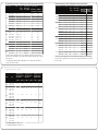
The cable and fuse sizes for Vacon
®
100 in North America, mains voltage 208-240 V and 380-500 V
Frame Type IL [A] Fuse
(Class
T/J) [A]
Mains, motor and
brake resistor*
cable Cu [AWG]
Terminal cable size
Mains cable
terminal [AWG]
Grounding
terminal [AWG]
MR4
0003 2 / 0003 5 3.7 / 3.4 6 14 24-10 17-10
0004 2 / 0004 5 4.8 6 14 24-10 17-10
0006 2 / 0005 5 6.6 / 5.6 10 14 24-10 17-10
0008 2 / 0008 5 8.0 10 14 24-10 17-10
0011 2 / 0009 5 11.0 / 9.6 15 14 24-10 17-10
0012 2 / 0012 5 12.5 / 12.0 20 14 24-10 17-10
MR5
0018 2 / 0016 5 18.0 / 16.0 25 10 20-5 17-8
0024 2 / 0023 5 24.0 / 23.0 30 10 20-5 17-8
0031 2 / 0031 5 31.0 40 8 20-5 17-8
MR6
0038 5 38.0 50 4 13-0 13-2
0048 2 / 0046 5 48.0 / 46.0 60 4 13-0 13-2
0062 2 / 0061 5 ** 62.0 / 61.0 80 4 13-0 13-2
** = To obey the UL regulations with the 500 V drive, it is necessary to have cables with a
+ 90 °C (+194 °F) heat resistance.
MR7
0075 2 / 0072 5 75.0 / 72.0 100 2 9-2/0
0088 2 / 0087 5 88.0 / 87.0 110 1 9-2/0
0105 2 / 0105 5
105.0
150 1/0 9-2/0
MR8
0140 2 / 0140 5
140.0
25 3/0
1 AWG-350 kcmil
0170 2 / 0170 5
170.0
30 250 kcmil
0205 2 / 0205 5 205.0 40 350 kcmil
MR9
0261 2 / 0261 5 261.0 60 2x250 kcmil
0310 2 / 0310 5 310.0 80 2x350 kcmil
9-2/0
9-2/0
9-2/0
1 AWG-350 kcmil
1 AWG-350 kcmil
1 AWG-350 kcmil
1 AWG-350 kcmil
1 AWG-350 kcmil
1 AWG-350 kcmil
1 AWG-350 kcmil
1 AWG-350 kcmil
1 AWG-350 kcmil
The cable and fuse sizes for Vacon
®
100 in North America, mains voltage 525-600 V
Frame Type IL [A] Fuse
(Class
T/J) [A]
Mains, motor and
brake resistor*
cable Cu [AWG]
Terminal cable size
Mains cable
terminal [AWG]
Grounding
terminal [AWG]
MR5
(600V)
0004 6 3.9 6 14 20-5 17-8
0006 6 6.1 10 14 20-5 17-8
0009 6 9.0 10 14 20-5 17-8
0011 6 11.0 15 14 20-5 17-8
0013 7 13.5 20 12 13-0 13-2
0018 6 / 0018 7 18.0 20 10 13-0 13-2
MR6
0022 6 / 0022 7 22.0 25 10 13-0 13-2
0027 7 / 0027 7 27.0 30 8 13-0 13-2
0034 6 / 0034 7 34.0 40 8 13-0 13-2
MR7 0052 6 / 0052 7 52.0 60 6 9-2/0 9-2/0
0062 6 / 0062 7 62.0 70 4 9-2/0 9-2/0
0007 7 7.5 10 12 13-0 13-2
0010 7 10.0 15 12 13-0 13-2
0041 6 / 0041 7 41.0 50 6 9-2/0 9-2/0
* = If you use a multi-conductor cable, 1 of the conductors of the brake resistor cable stays
unconnected. It is also possible to use a single cable if you obey the minimum cross-sectional
area of the cable.
The tightening torques of the terminals
Frame Type
Tightening torque: the
mains cable and motor
cable terminals
Tightening torque: the
grounding clamps for
cable shield
Tightening torque: the
grounding clamps for
grounding conductor
Nm lb-in. Nm lb-in. Nm lb-in.
MR4
0003 2 - 0012 2
0003 5 - 0012 5
0.5-0.6 4.5-5.3 1.5 13.3 2.0 17.7
MR5
0018 2 - 0031 2
0016 5 - 0031 5
0004 6 - 0011 6
1.2-1.5 10.6-13.3 1.5 13.3 2.0 17.7
MR6
0048 2 - 0062 2
0038 5 - 0061 5
0018 6 - 0034 6
0007 7 - 0034 7
10 88.5 1.5 13.3 2.0 17.7
MR7
0075 2 - 0105 2
0072 5 - 0105 5
0041 6 - 0062 6
0041 7 - 0062 7
8 * / 5.6 **
70.8 * /
49.6 **
1.5 13.3 8 * / 5.6 **
70.8 * /
49.6 **
* = The tightening torque for a torx screw.
** = The tightening torque for an Allen screw.
MR8
0140 2 - 0205 2
0140 5 - 0205 5
0080 6 - 0125 6
0080 7 - 0125 7
30 266 1.5 13.3 20 177
MR9
0261 2 - 0310 2
0261 5 - 0310 5
0144 6 - 0208 6
0144 7 - 0208 7
40 266 1.5 13.3 20 177
MR8
0080 6 / 0080 7 80.0 90 1/0
0100 6 / 0100 7 100.0 110 1/0
0125 6 / 0125 7
125.0
150 2/0
MR9
0144 6 / 0144 7
144.0 175
3/0 1 AWG-350 kcmil
0170 7 170.0 200 4/0
0208 6 / 0208 7
208.0 250 300 kcmil
1 AWG-350 kcmil
1 AWG-350 kcmil
1 AWG-350 kcmil
1 AWG-350 kcmil
1 AWG-350 kcmil
1 AWG-350 kcmil
1 AWG-350 kcmil
1 AWG-350 kcmil
1 AWG-350 kcmil
1 AWG-350 kcmil
1 AWG-350 kcmil
* = If you use a multi-conductor cable, 1 of the conductors of the brake resistor cable stays
unconnected. It is also possible to use a single cable if you obey the minimum cross-sectional
area of the cable.
-
 1
1
-
 2
2


Vacon 100 Industrial Operating instructions
- Category
- Signal cables
- Type
- Operating instructions
Ask a question and I''ll find the answer in the document
Finding information in a document is now easier with AI
Related papers
-
Vacon 100 FLOW Operating instructions
-
-
-
Vacon 100HVAC(old ctrl) Installation guide
-
Vacon 100 Industrial Installation guide
-
-
-
-
-
Other documents
-
Hyundai N800A Installation guide
-
Danfoss VACON 100 FLOW User guide
-
Ibanez SRMS Owner's manual
-
Mackie Speaker MR8 User manual
-
Mackie MR5 User manual
-
-
Danfoss 100 FLOW Installation guide
-
Eaton HMX32AG01822-N Installation guide
-
Molex 207129 Series User manual
-
Philips 42PFL9903H/10 User manual