Page is loading ...

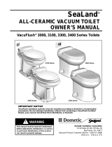
SANITATION
TOILETS
9300/9400/9500
EN
9000 Series
Installation Manual

2
EN
Toilets
NORTH AMERICAN ADDRESS INFORMATION
U.S.A. & CANADA
Service Office
Dometic Corporation
13128 St. Rte. 226
Big Prairie, OH 44611
Service Center & Dealer
Locations
Refer to “8 Customer service” on
page 18
Form No. 600347473 06/18 | ©2018 Dometic Corporation
Read these instructions carefully. These instructions MUST stay with this product.
CONTENTS
1 Explanation of symbols and safety instructions. . . . . . . . . . . . . . . . . . . . . . . . . . . . . . . . . . 3
2 General information ....................................................... 4
3 Intended use ............................................................ 4
4 Specifications ............................................................ 5
5 Prepare for installation ..................................................... 7
6 Installation ..............................................................12
7 Disposal ................................................................15
8 Customer service .........................................................15

3
EN
Toilets
1 EXPLANATION OF SYMBOLS AND SAFETY INSTRUCTIONS
This manual has safety information and instructions to help you eliminate or reduce the risk of
accidents and injuries.
1.1 Recognize safety information
This is the safety alert symbol. It is used to alert you to potential physical injury hazards.
Obey all safety messages that follow this symbol to avoid possible injury or death.
1.2 Understand signal words
A signal word will identify safety messages and property damage messages, and will indicate the
degree or level of hazard seriousness.
indicates a hazardous situation that, if not avoided, could result in death or
serious injury.
indicates a hazardous situation that, if not avoided, could result in minor or
moderate injury.
is used to address practices not related to physical injury.
I
indicates additional information that is not related to physical injury.
1.3 Supplemental directives
Read and follow all safety information and instructions to avoid possible injury or death.
Read and understand these instructions before installation of this product.
Incorrect installation of this product can lead to serious injury.
The installation must comply with all applicable local or national codes, including the
latest edition of the following standards:
U.S.A.
• ANSI/NFPA70, National Electrical Code (NEC)
• ABYC guidelines for marine installations
1.4 General safety messages
Failure to obey the following warnings could result in death, serious injury, or
property damage:
• This product must be installed and serviced by a qualified service technician.
• Do not modify this product in any way. Modifi cation can be extremely hazardous.
• SHOCK OR FIRE HAZARD: Always use recommend fuse, circuit breaker, and wire size. Failure
to do so can result in a fire that can cause the loss of property and life.
• FLOOD HAZARD:
– Seacocks must be installed in all piping connected to through-the-hull fittings. Seacocks
must be easily accessible to all users of the toilet, or secondary valves should be fitted in
hose runs where they are easily accessible.
– If the toilet is connected to any through-the-hull fittings: always close seacocks when
toilet is not in use (even if the boat is unattended for a brief period).

4
EN
Toilets
– Valves must be full-bore valves of marine sanitation quality. Do not use screw-to-close
gate valves.
– Flexible hoses must be of marine sanitation quality and must be secured to any fittings
with two stainless steel, worm-drive, hose-band clamps at each connection. Check
connections frequently for integrity.
– Use properly positioned, ventilated loops when the potential exists for the toilet rim to
fall below the waterline during any heel, load, or trim condition, or when the toilet is
connected to any through-the hull fittings. The ventilated loops must be installed in the
intake (if connected to raw water) and/or the discharge piping.
– Ensure that all electrical power to the toilet is turned off and that seacocks are in the
closed or off position before installing the toilet or performing any maintenance.
– If the toilet uses fresh water for flushing and is connected directly or indirectly to a
shore side municipal water system at any time: shoreside water connections must be
disconnected if the boat is unattended (even if boat is unattended for a brief period).
– If the toilet is connected to any through-the-hull fittings: all flexible hoses must be of
marine sanitation quality and must be secured to any fittings (such as those at seacock,
vented loop, or toilet) with two stainless steel worm-drive hose band clamps at each
connection. Connections must be checked frequently for integrity.
– If the toilet uses raw water for flushing at any time, a raw-water pump controlled by an
automatically operat ing demand switch must not be installed. If the onboard water
valve or any plumbing connections were to leak, the automatically operated pump
would start and could flood the boat.
RISK OF PROPERTY DAMAGE: Failure to obey the following notices may cause
damage to the toilet or toilet system.
• Only flush water, bodily wastes, and rapid-dissolving toilet tissue.
• Do not overfill the holding tank, or serious damage can occur to the sanitation system.
Overfilling the holding tank can rupture the holding tank or release tank contents into the
bilge.
• This toilet system is not intended for raw water flush toilet systems and is not designed to
flush with seawater. Only use a fresh water supply.
2 GENERAL INFORMATION
Included Parts
RushFlush toilet High-flow electric water valve
Check valve Maintenance valve
Flush switch and status panel (9400 and 9500 only)
Optional Parts*
System status panel (9300 only)
*Available as accessory (not included)

5
EN
Toilets
3 INTENDED USE
The 9000 Series RushFlush toilets are designed and intended for use inside the boat for which it is
supplied. RushFlush toilets are not intended for use with a raw water or seawater flush system. Use
the instructions to ensure correct operation of the toilet. Dometic accepts no liability for damage
in the following cases:
• Faulty assembly or connection.
• Damage to the product resulting from mechanical influences and excess voltage.
• Alterations to the product without expressed permission from Dometic Corporation.
• Use for purposes other than those described in the operating manual.
Dometic Corporation reserves the right to modify appearances and specifications without notice.
4 SPECIFICATIONS
4.1 Materials
Component 9300, 9400, 9500
Toilet vitreous ceramic
Control module housing ABS plastic
Discharge outlet high-tech polymer
Discharge flange ABS plastic
Panel frame ABS plastic
Panel polycarbonate resin
Flush handle plated brass*
*applicable models

6
EN
Toilets
4.2 Minimum system requirements
Electrical
Power draw 1.2 A @ 12 VDC/0.6 A @ 24 VDC
Circuit breaker/
fuse recommended size
2 A @ 12 VDC/1 A @ 24 VDC
Water Supply
Upper rim 1/2" NPT inlet, water valve
Lower bowl jet 1" NPT inlet, water valve
Flow rate 15 gpm (57 lpm) @ 30–50 PSI (207–345 kPa)
Discharge
Inside diameter (ID) 1.5" (38 mm) pipe or 1.875" (47 mm) hose
Horizontal run gravity drain*
Required Components
Water pump** 15 gpm (57 lpm)
Potable water pressure tank** 150 PSI (1034 kPa) working pressure rating
Electric flush switch Dometic model
*Horizontal discharge plumbing must drop a minimum of 1/8" (3 mm) per foot (30.5 cm) of
horizontal run.
** Purchased separately. Water pump may be part of vessel’s potable water system.
I
Specifications are subject to change without notice.

7
EN
Toilets
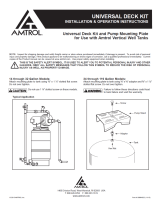
4.3 Dimensions
9300 Series
1
A
E
F
C
B
D
2
G
9400 Series
3
A
E
F
C
B
D
4
G
9500 Series
5
A
E
F
C
B
D
6
G
Reference 9300 Series 9400 Series 9500 Series
A 19" 19" 19"
B 16.5"* 14" 14.75"
C 21.5" 21.5" 22"
D 17.5" 17.5" 17.5"
E 17" 17" 17.5"
F 10.5" 10.5" 10.5"
G 33.5" 33.5" 37"
*Width measurement includes flush handle

8
EN
Toilets
OK TO
FLUSH
DO NOT
FLUSH
7
A
C
B
8
A
C
B
9
A
B
Reference
Flush Switch (DFS)
(Figure 7)
Touchpad (DFT)
(Figure 8)
Touch Panel
(DFSHW)
(Figure 9)
A 3" 2" 3"
B 3.4" 3.25" 3.4"
C .4" 0.4375" .4”
5 PREPARE FOR INSTALLATION
Failure to obey the following warnings could result in property damage, serious
injury, or death:
• FLOOD HAZARD. For toilets that use raw-water systems: Do not install a raw-water pump
controlled by an automatic demand switch.
• SHOCK OR FIRE HAZARD. Always use recommend fuse, circuit breaker, and wire size. Failure
to do so can result in a fire that can cause the loss of property and life.
C

9
EN
Toilets
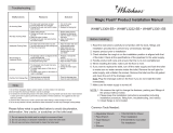
5.1 Understanding requirements for the fresh-water system
10
Switch/Status Panel
Blackwater
Holding Tank
Freshwater
Holding Tank
Lower Bowl Water
Supply Line
Fresh Water To
Other Fixtures
Pressure
Gauge
(0–100 PSI)
1" Pump
Inlet Strainer
(40 mesh)
Toilet
5-Gallon
Potable Water
Pressure Tank
(30/50 PSI)
High-flow
Water Pump
Rim Water
Supply Line
Check
Valve
Check
Valve
Electric High-flow
Water Jet Valve
Maintenance
Ball Valve
General guidelines
• Follow all applicable local and national regulations, codes, and standards
• All water supply system plumbing should be 1" ID with a recommended 100 PSI minimum
working pressure rating
• Water inlet strainer: 1" ID, 40 mesh
• Pressure gauge: 0 – 100 PSI
Water pump guidelines
• Grundfos MQ3-35 or equivalent is recommended
• 1" NPT connections
• Internal pressure switch: 50 PSI cut-out, 30 PSI cut-in
• MQ3 Pump draw: 8 A @110 V, 4 A @ 220 V (pumps vary by manufacturer)
• 15 gpm required (MQ3 pump rated at 22 GPM max flow with no restrictions)
• Choose a pump with adequate suction li capability for pump installation parameters (MQ3
pump has 25' of suction life capability, but varies depending on horizontal run)
Potable water pressure (accumulator) tank guidelines
• Amtrol Well-X-Trol WX-105-PS or equivalent is recommended
• 3/4" NPT, or larger connections
• 5 gallon total volume, 1.8 gallon drawdown @ 30/50 PSI
• Air pressure charge: 2-4 PSI below pump cut-in pressure
• Recommended to use one five-gallon accumulator tank for up to six heads
Pressure relief valve guidelines
I
Installation of a pressure relief valve is recommended by the accumulator tank
manufacturer in order to protect the fresh water system in case of pressure switch
malfunction.
• Install near accumulator tank and pump
• Set to open at excessive water system pressures

10
EN
Toilets
Electric rim wash valve guidelines (inside toilet)
• 1/2" NPT connection
• 1/2" plumbing to the toilet. If using a single water supply line, this 1/2" branch must intersect
with the main 1" distribution line prior to the electric high-flow water valve.
Electric high-flow water jet valve guidelines
• Electric high-flow water jet valve and maintenance ball valve supplied with every toilet
• 1" NPT connections
• Place water jet valve closest to toilet and the maintenance ball valve farthest from the toilet
– Refer to direction arrow on top of the water jet valve inlet port
• In-line strainer factory-installed in the water jet valve inlet
– Cone shape protrudes out against the direction of water flow, away from the center of
the valve, and is pointed towards the maintenance ball valve
• Water jet valve has a small white manual override lever located by the solenoid:
– Place in vertical position for correct electrical operation
– Place in horizontal position to manually test the water system
Discharge plumbing guidelines
• Keep all lines as short and straight as possible
• Minimum downhill slope required: 1/8" per foot
• 1-1/2" ID pipe or 1-7/8" ID hoses required
– For 1-1/2" pipe:
• Requires drain, waste, and vent (DWV) pipe fittings with sweeping changes of
direction
• Do not use schedule 40 or 80 fittings with tight turns
• Install unions, as necessary, for service
– For 1-7/8" hose, eliminate hose sags and low spots
Check valve guidelines
• Flapper style supplied with every toilet
• Spring check: 1"
• Install valve:
– Close to the toilet
– On the discharge side of the toilet plumbing
– Before the waste line joins with any common discharge line
– When open, the flapper “hinge” must be at the highest possible location
– So the flapper opens in-line with the direction of the water flow
• When gluing the valve in place, do not allow excess glue to contact the flapper
• When flushing overboard through the seacock:
– Loop inside the toilet must be above the waterline
– Seacock must be 1-1/2" full-flow and located no lower than 12" below the water line
I

11
EN
Toilets
5.2 Planning the electrical connections (Models 9400 and 9500)
I
Plan the switch/status panel location, if applicable, so that the wiring cable and
connections are installed in locations that always remain dry. Use the length of the
provided wiring cable to help space the electrical connections at the proper distance
from the toilet.
11
Floor
Wall
➤ Place the wall switch template in the
desired location.
➤ Mark the location of the fastener and
access holes.
12
Floor
Wall
➤ Remove the template from the wall.
➤ Drill a 1" diameter hole in the center and
fasten the panel bracket to the wall.
5.3 Identifying centerline and access hole locations
Through-the-floor method
13
Discharge
Floor Flange
Discharge
Floor Flange
Floor
Floor
(Below-Finished Floor Level Installation)
(Above-Finished Floor Level Installation)
Rim
Spacer
Sub-Floor
Sub-Floor
China Toilet
Base-Rear
China Toilet
Base-Rear
3/8" (10 mm)
max. distance
3/8" (10 mm)
max. distance
Rim
➤ For through-the-floor connections, use the below-floor installation method, when possible.
I
The discharge floor flange should be installed directly on the finished floor. However, if
the bottom of the floor flange and the bottom of the toilet must be at different heights,
make sure the bottom of the discharge floor flange rim is within 3/8” (10 mm) of the
bottom of the toilet, regardless of the installation method.

12
EN
Toilets
14
2"
Rear Corner
of Bowl
(Floor)
6"
14"
10.5"
3.25"
Overall Bowl Width
A
B
C
E
D
4"
15
4.25"
A
B
C
1.5"
1.5"
Floor
Wall
Reference Name
A Discharge flange access hole
B Upper rim water supply line and electrical wire access hole
C Lower bowl water supply line access hole
D Primary centerline
E Secondary centerline
Through-the-wall method
16
1.5"
Floor
Overall Bowl Width
Wall
3"
4"
A
D
F
(14" min.)
C
B
E
1.5"
4"
17
Wall
Floor
1.5"
2.25"
1.5"
B
C
A
Reference Name
A Discharge outlet access hole
B Upper rim water supply line and electrical wire access hole
C Lower bowl water supply line access hole
D Primary centerline
E Horizontal primary centerline
F Secondary centerline

13
EN
Toilets
Marking the locations (applicable to both methods)
➤ Position the bowl in the designated toilet location.
➤ Confirm that adequate clearance exists for the seat and lid to open freely and (for 9300 series
only) the flush handle to operate easily on the le side of the toilet.
➤ Mark the rear corners of the bowl and set the bowl aside.
➤ Measure the distance between the two rear corner marks and divide the measurement in half
to identify the primary centerline location.
➤ Draw the primary centerline a minimum of 14” long.
– If using the through-the-wall method, also mark the horizontal primary centerline.
➤ Mark the center of the discharge flange access hole.
➤ Mark the center of the upper rim water supply line and electrical wires access hole.
➤ Draw the secondary centerline a minimum of 4” long.
➤ Mark the center of the lower bowl water supply line access hole.
➤ Drill the discharge flange access hole.
➤ Drill the upper rim water supply line and electrical wires access hole.
➤ Drill the lower bowl water supply line access hole.

14
EN
Toilets
6 INSTALLATION
6.1 Installing the toilet with through-the-floor connections
18
Discharge
Flange
#14 x 1-1/2"
Screw
Sealing
Grommet
Washer
➤ Turn the electrical power OFF.
➤ Align the discharge flange with slots
facing front-to-back, then insert the
discharge flange into the discharge flange
access hole.
➤ Loosely secure the discharge flange using
the #14 × 1-1/2" screws and washers
(provided).
➤ Place the sealing grommet into the top
of the discharge flange and lubricate
the inside of the grommet hole
using dish soap.
19
Toilet
(Rear)
Floor
Mounting
Bolt Location
Sealing
Grommet
Discharge
Outlet
➤ Carefully lower the toilet, keeping it level,
until the toilet discharge outlet slides into
the sealing grommet and the toilet base
rests flat on the floor.
➤ Slide the toilet front-to-back (no more than
1/2" each direction) until the toilet bowl is
straight and in the desired location.
➤ Mark the mounting bolt locations using
the holes as a guide.
➤ Carefully raise the toilet and set aside.
➤ Tighten the discharge flange screws.
➤ Drill 3/16" pilot holes for the mounting bolts.
➤ Proceed to “6.3 Finalizing the installation”
on page 15.
6.2 Installing the toilet with through-the-wall connections
20
➤ Place the toilet in the desired location.
➤ Mark the mounting bolt locations using
the holes as a guide.
➤ Carefully move the toilet aside and drill
3/16" pilot holes for the mounting bolts.
21
Lower Bowl
Water Supply Line
Access Hole
Elbow Fitting
➤ Install an elbow fitting (not provided) for
the lower bowl water supply line.
➤ Proceed to “6.3 Finalizing the installation”
on page 15.

15
EN
Toilets
6.3 Finalizing the installation
22
Lower Bowl
Water Supply
Line
Upper Rim
Water Supply
Line
Wiring
➤ Route a 1/2" ID upper rim water supply
line through the access hole. Use a
1/2" NPT connection (not provided).
➤ Route a 1" ID lower bowl water supply
line through the access hole. Leave
approximately 3' of extra line attached in
order to make a flexible loop.
➤ Route #18 gauge stranded copper wire
from the DC power source (positive and
ground) through a fuse or circuit breaker.
Leave at least 18" of wire for the toilet
connection.
➤ Route wiring to the toilet location.
I
Route all other optional wiring
according to the wiring diagrams.
23
Flush
Switch
Touchpad
Ethernet
Cable
Ethernet
Cable
Flush switch (9400/9500)/system status
panel (optional 9300) installation
➤ Route the touchpad or flush switch Ethernet
cables from the Ethernet connection on the
toilet control module through the access hole
in the wall.
➤ Plug the Ethernet cable into the touchpad or
flush-switch panel.
➤ Snap the touchpad or flush-switch panel onto
the panel bracket.

16
EN
Toilets
24
Toilet
(Rear)
Lower
Bowl Water
Supply Line
Upper
Rim Water
Supply Line
Wiring
➤ Connect the discharge plumbing
from the holding tank to the discharge
flange or waste outlet. See section “5.1
Understanding requirements for the fresh-
water system” on page 9.
➤ Position the toilet near the discharge flange.
➤ Connect the upper rim water supply line
to the water valve.
➤ Route the wiring for the control module
through the wiring access hole and up
through the toilet plumbing lines.
➤ Connect the lower bowl water supply line
to the toilet, looping the line as shown.
– For through-the-wall installations, loop
through the elbow fitting down to the
inlet at the toilet base.
25
Control
Module
Switch
Connector
Toilet
(Rear)
Sealing
Grommet
➤ Remove the control module from the
inside and back of the toilet.
➤ Attach the panel cable to the toilet control
module (RJ45 connector).
➤ Reattach the control module to the back
of the toilet.
➤ Set the toilet back in place by inserting
the discharge outlet into the sealing
grommet.
26
Bolt
Cover
I
Do not slide the toilet over the
discharge flange. Carefully align and
place over the adapter to prevent
possible damage.
➤ Adjust the toilet so the toilet mounting
bolt holes are aligned with the pilot holes
and the discharge adapter is aligned with
the sealing grommet in the floor flange.
Press straight down to secure.
➤ “Test the toilet for leaks” before proceeding.
➤ Secure the toilet to the floor, using #14
x 2-1/2” lag bolts. Push the decorative
covers onto the bolt heads.
Test the toilet for leaks
➤ Turn on the water supply and electrical
power to the toilet.
➤ Li the flush handle, or push “add water”
button for several seconds.
➤ Flush the toilet multiple times to observe
operation. To adjust flush duration,
see section “6.4 Adjusting the water
consumption settings” on page 17.
➤ Wait one hour and check for leaks on the
floor and at the rear of the toilet.

17
EN
Toilets
6.4 Adjusting the water consumption settings
RIM
–
+
JET
–
+
27
Toilet
(Rear)
Control
Module
➤ Locate the water control module at the
inside and rear of the toilet.
➤ Turn the rim and/or lower water jet
control knobs to adjust the flow time for
each area.
– Increase flow: turn the dial
clockwise.
– Decrease flow: turn the dial counter-
clockwise.

18
EN
Toilets
7 DISPOSAL
M
Place the packaging material in the appropriate recycling waste bins, whenever possible.
Consult a local recycling center or specialize dealer for details about how to dispose of
the product in accordance with all applicable national and local regulations.
8 CUSTOMER SERVICE
For the Authorized Service Center near you, call between 8:00 a.m. and 5:00 p.m. (ET), Monday
through Friday, or contact the nearest Parts Distributor.
Telephone: 1 800-321-9886 U.S.A. and Canada
330-439-5550 International
Fax:
330-496-3097 U.S.A. and Canada
330-439-5567 International
Website: www.dometic.com
/