Page is loading ...

DSE7110 MKII & DSE7120 MKII Operator Manual ISSUE 2
DEEP SEA ELECTRONICS PLC
DSE7110 MKII & DSE7120 MKII
Operator Manual
Document Number: 057-182
Author: Ashley Senior

DSE7110 MKII & DSE7120 MKII Operator Manual
2
DEEP SEA ELECTRONICS PLC
Highfield House
Hunmanby
North Yorkshire
YO14 0PH
ENGLAND
Sales Tel: +44 (0) 1723 890099
Sales Fax: +44 (0) 1723 893303
E-mail: sales@deepseaplc.com
Website: www.deepseaplc.com
DSE7110 MKII & DSE7120 MKII Operator Manual
© Deep Sea Electronics Plc
All rights reserved. No part of this publication may be reproduced in any material form (including
photocopying or storing in any medium by electronic means or other) without the written permission
of the copyright holder except in accordance with the provisions of the Copyright, Designs and
Patents Act 1988.
Applications for the copyright holder’s written permission to reproduce any part of this publication
should be addressed to Deep Sea Electronics Plc at the address above.
The DSE logo is a UK registered trademarks of Deep Sea Electronics PLC.
Any reference to trademarked product names used within this publication is owned by their
respective companies.
Deep Sea Electronics Plc reserves the right to change the contents of this document without prior
notice.
Amendments List
Issue Comments
Minimum Module
Version Required
1 Initial release V 1.0.0
2
Added changes to Front Panel Editor and new part number for installation
instructions
V1.1.58
Typeface: The typeface used in this document is Arial. Care should be taken not to mistake the upper case letter I with the numeral 1. The
numeral 1 has a top serif to avoid this confusion.
Clarification of notation used within this publication.
NOTE
Highlights an essential element of a procedure to ensure correctness.
CAUTION!
Indicates a procedure or practice, which, if not strictly observed, could
result in damage or destruction of equipment.
WARNING!
Indicates a procedure or practice, which could result in injury to
personnel or loss of life if not followed correctly.

DSE7110 MKII & DSE7120 MKII Operator Manual
3
TABLE OF CONTENTS
Section Page
1
BIBLIOGRAPHY .............................................................................................. 7
1.1
INSTALLATION INSTRUCTIONS .................................................................................. 7
1.2
TRAINING GUIDES ........................................................................................................ 7
1.3
MANUALS ...................................................................................................................... 7
1.4
THIRD PARTY DOCUMENTS ........................................................................................ 7
2
INTRODUCTION .............................................................................................. 8
3
SPECIFICATION .............................................................................................. 9
3.1
SHORT NAMES .............................................................................................................. 9
3.2
OPERATING TEMPERATURE ....................................................................................... 9
3.3
REQUIREMENTS FOR UL CERTIFICATION ................................................................. 9
3.4
TERMINAL SPECIFICATION ....................................................................................... 10
3.5
POWER SUPPLY REQUIREMENTS ............................................................................ 10
3.5.1
MODULE SUPPLY INSTRUMENTATION DISPLAY .............................................. 10
3.6
VOLTAGE & FREQUENCY SENSING ......................................................................... 11
3.7
CURRENT SENSING .................................................................................................... 11
3.7.1
VA RATING OF THE CTS ...................................................................................... 12
3.7.2
CT POLARITY........................................................................................................ 13
3.7.3
CT PHASING ......................................................................................................... 13
3.7.4
CT CLASS ............................................................................................................. 13
3.8
INPUTS......................................................................................................................... 14
3.8.1
DIGITAL INPUTS ................................................................................................... 14
3.8.2
ANALOGUE INPUTS ............................................................................................. 14
3.8.2.1
OIL PRESSURE .............................................................................................. 14
3.8.2.2
COOLANT TEMPERATURE ........................................................................... 14
3.8.2.3
FUEL LEVEL SENSOR ................................................................................... 15
3.8.2.4
FLEXIBLE SENSOR ........................................................................................ 15
3.8.3
CHARGE FAIL INPUT ............................................................................................ 15
3.8.4
MAGNETIC PICKUP .............................................................................................. 16
3.9
OUTPUTS..................................................................................................................... 16
3.9.1
DC OUTPUTS A & B (FUEL & START) .................................................................. 16
3.9.2
CONFIGURABLE VOLT-FREE OUTPUTS C & D .................................................. 16
3.9.3
CONFIGURABLE DC OUTPUTS E, F, G & H ........................................................ 16
3.10
COMMUNICATION PORTS ...................................................................................... 17
3.10.1
COMMUNICATION PORT USAGE ....................................................................... 17
3.10.1.1
CAN INTERFACE .......................................................................................... 17
3.10.1.2
USB CONNECTION ........................................................................................ 18
3.11
ADDING AN EXTERNAL SOUNDER ........................................................................ 19
3.12
ACCUMULATED INSTRUMENTATION .................................................................... 19
3.13
DIMENSIONS AND MOUNTING ............................................................................... 20
3.13.1
DIMENSIONS ........................................................................................................ 20
3.13.2
PANEL CUTOUT.................................................................................................... 20
3.13.3
WEIGHT ................................................................................................................ 20
3.13.4
FIXING CLIPS ........................................................................................................ 21
3.13.5
CABLE TIE FIXING POINTS .................................................................................. 22
3.13.6
SILICON SEALING GASKET ................................................................................. 22
3.13.7
APPLICABLE STANDARDS ................................................................................... 23
3.13.8
ENCLOSURE CLASSIFICATIONS ......................................................................... 25
3.13.8.1
IP CLASSIFICATIONS .................................................................................... 25
3.13.8.2
NEMA CLASSIFICATIONS ............................................................................. 26
4
INSTALLATION ............................................................................................. 27
4.1
TERMINAL DESCRIPTION .......................................................................................... 28
4.1.1
DC SUPPLY, E-STOP INPUT, DC OUTPUTS & CHARGE FAIL INPUT ................ 28

DSE7110 MKII & DSE7120 MKII Operator Manual
4
4.1.2
ANALOGUE SENSORS ......................................................................................... 29
4.1.3
MPU & CAN ........................................................................................................... 29
4.1.4
OUTPUT C & D & GENERATOR VOLTAGE & FREQUENCY SENSING ............... 30
4.1.5
MAINS VOLTAGE & FREQUENCY SENSING (7120 MKII ONLY) ......................... 30
4.1.6
CURRENT TRANSFORMERS ............................................................................... 31
4.1.6.1
CT CONNECTIONS ........................................................................................ 31
4.1.7
CONFIGURABLE DIGITAL INPUTS ...................................................................... 32
4.1.8
PC CONFIGURATION INTERFACE CONNECTOR ............................................... 32
4.2
TYPICAL WIRING DIAGRAM ....................................................................................... 33
4.2.1
DSE7110 MKII TYPICAL WIRING DIAGRAM (3 PHASE 4 WIRE) ......................... 34
4.2.2
DSE7120 MKII TYPICAL WIRING DIAGRAM (3 PHASE 4 WIRE) ......................... 35
4.3
ALTERNATE TOPOLOGY WIRING DIAGRAMS ......................................................... 36
4.3.1
GENERATOR ........................................................................................................ 36
4.3.2
MAINS (DSE7120 MKII ONLY)............................................................................... 37
4.4
EARTH SYSTEMS ........................................................................................................ 38
4.4.1
NEGATIVE EARTH ................................................................................................ 38
4.4.2
POSITIVE EARTH ................................................................................................. 38
4.4.3
FLOATING EARTH ................................................................................................ 38
5
DESCRIPTION OF CONTROLS .................................................................... 39
5.1
DSE7110 MKII .............................................................................................................. 40
5.2
DSE7120 MKII .............................................................................................................. 41
5.3
CONTROL PUSH-BUTTONS ....................................................................................... 42
5.4
MODULE DISPLAY ...................................................................................................... 45
5.4.1
BACKLIGHT ........................................................................................................... 46
5.4.2
INSTRUMENTATION ICONS ................................................................................. 46
5.4.3
ACTIVE CONFIGURATION ................................................................................... 47
5.4.4
FRONT PANEL EDITOR (FPE) / AUTO RUN ICON ............................................... 47
5.4.5
MODE ICON .......................................................................................................... 47
5.4.6
ALARM ICONS (PROTECTIONS) .......................................................................... 48
5.4.6.1
WARNING ALARM ICONS ............................................................................. 49
5.4.6.2
ELECTRICAL TRIP ALARM ICONS ................................................................ 50
5.4.6.3
SHUTDOWN ALARM ICONS .......................................................................... 51
5.5
VIEWING THE INSTRUMENT PAGES ......................................................................... 53
5.5.1
NAVIGATION MENU .............................................................................................. 53
5.5.1.1
NAVIGATION MENU ICONS ........................................................................... 53
5.5.2
GENERAL NAVIGATION ....................................................................................... 54
5.5.3
HOME .................................................................................................................... 55
5.5.4
GENERATOR ........................................................................................................ 55
5.5.5
MAINS (DSE7120 MKII ONLY)............................................................................... 56
5.5.6
LOAD ..................................................................................................................... 56
5.5.7
ENGINE ................................................................................................................. 57
5.5.8
INFO ...................................................................................................................... 57
5.5.9
ENGINE DTC (ECU ALARMS) ............................................................................... 58
5.5.9.1
VIEWING ACTIVE ENGINE DTC .................................................................... 58
5.5.10
EVENT LOG .......................................................................................................... 60
5.5.10.1
VIEWING THE EVENT LOG ........................................................................... 61
6
OPERATION .................................................................................................. 62
6.1
QUICKSTART GUIDE .................................................................................................. 62
6.1.1
STARTING THE ENGINE ...................................................................................... 62
6.1.2
STOPPING THE ENGINE ...................................................................................... 63
6.2
STOP/RESET MODE.................................................................................................... 64
6.3
MANUAL MODE ........................................................................................................... 65
6.3.1
STARTING SEQUENCE ........................................................................................ 65
6.3.2
ENGINE RUNNING ................................................................................................ 66
6.3.3
STOPPING SEQUENCE ........................................................................................ 66
6.4
TEST MODE ................................................................................................................. 67
6.4.1
STARTING SEQUENCE ........................................................................................ 67
6.4.2
ENGINE RUNNING ................................................................................................ 68

DSE7110 MKII & DSE7120 MKII Operator Manual
5
6.4.3
STOPPING SEQUENCE ........................................................................................ 68
6.5
AUTOMATIC MODE .................................................................................................... 69
6.5.1
WAITING IN AUTO MODE..................................................................................... 69
6.5.2
STARTING SEQUENCE ........................................................................................ 69
6.5.3
ENGINE RUNNING ................................................................................................ 70
6.5.4
STOPPING SEQUENCE ........................................................................................ 70
6.6
MAINTENANCE ALARM .............................................................................................. 71
6.7
SCHEDULER ................................................................................................................ 72
6.7.1
STOP MODE ......................................................................................................... 72
6.7.2
MANUAL MODE..................................................................................................... 72
6.7.3
TEST MODE .......................................................................................................... 72
6.7.4
AUTO MODE ......................................................................................................... 72
7
FRONT PANEL CONFIGURATION ............................................................... 73
7.1
ACCESSING THE FRONT PANEL CONFIGURATION EDITOR .................................. 74
7.2
ADJUSTABLE PARAMETERS ..................................................................................... 75
7.2.1
MODULE SETTINGS ............................................................................................. 75
7.2.2
CAN SETTINGS ..................................................................................................... 75
7.2.3
INPUT SETTINGS ................................................................................................. 76
7.2.4
OUTPUT SETTINGS.............................................................................................. 77
7.2.5
TIMER SETTINGS ................................................................................................. 78
7.2.6
GENERATOR SETTINGS ...................................................................................... 79
7.2.7
MAINS SETTINGS ................................................................................................. 80
7.2.8
ENGINE SETTINGS............................................................................................... 81
7.2.9
ANALOGUE INPUTS SETTINGS ........................................................................... 82
7.2.10
SCHEDULER SETTINGS....................................................................................... 84
7.2.11
TIME AND DATE SETTINGS ................................................................................. 84
7.2.12
MAINTENANCE ALARM SETTINGS...................................................................... 85
7.2.13
ALTERNATE CONFIGURATION SETTINGS ......................................................... 85
7.3
SELECTABLE PARAMETER SETTINGS .................................................................... 87
7.3.1
INPUT SOURCES .................................................................................................. 87
7.3.2
OUTPUT SOURCES .............................................................................................. 88
7.3.3
ALARM ACTION .................................................................................................... 90
7.3.4
FLEXIBLE SENSOR ALARM ACTION ................................................................... 90
7.3.5
POWER UP MODE ................................................................................................ 90
7.3.6
SENSOR TYPE ...................................................................................................... 90
7.3.7
AC SYSTEM .......................................................................................................... 90
7.3.8
DIGITAL INPUT ALARM ARMING ......................................................................... 91
7.3.9
DIGITAL INPUT POLARITY ................................................................................... 91
7.3.10
DIGITAL OUTPUT POLARITY ............................................................................... 91
7.3.11
FUEL UNITS .......................................................................................................... 91
7.3.12
PRESSURE SENSOR LIST ................................................................................... 92
7.3.13
TEMPERATURE SENSOR LIST ............................................................................ 92
7.3.14
PERCENTAGE SENSOR LIST .............................................................................. 92
8
COMMISSIONING .......................................................................................... 93
9
FAULT FINDING ............................................................................................ 94
9.1
STARTING ................................................................................................................... 94
9.2
LOADING ..................................................................................................................... 94
9.3
ALARMS ....................................................................................................................... 95
9.4
COMMUNICATIONS ..................................................................................................... 95
9.5
INSTRUMENTS ............................................................................................................ 95
9.6
MISCELLANEOUS ....................................................................................................... 96
10
MAINTENANCE, SPARES, REPAIR AND SERVICING ............................. 97
10.1
PURCHASING ADDITIONAL CONNECTOR PLUGS FROM DSE ............................ 97
10.1.1
PACK OF PLUGS .................................................................................................. 97
10.1.2
INDIVIDUAL PLUGS .............................................................................................. 97
10.2
PURCHASING ADDITIONAL FIXING CLIPS FROM DSE ......................................... 97

DSE7110 MKII & DSE7120 MKII Operator Manual
6
10.3
PURCHASING ADDITIONAL SEALING GASKET FROM DSE ................................. 97
11
WARRANTY ................................................................................................ 98
12
DISPOSAL .................................................................................................. 98
12.1
WEEE (WASTE ELECTRICAL AND ELECTRONIC EQUIPMENT)........................... 98

Bibliography
7
1 BIBLIOGRAPHY
This document refers to and is referred to by the following DSE publications which can be obtained
from the DSE website: www.deepseaplc.com
1.1 INSTALLATION INSTRUCTIONS
Installation instructions are supplied with the product in the box and are intended as a ‘quick start’
guide only.
DSE Part Description
053-151 DSE7110 MKII & DSE7120 MKII
Installation Instructions
053-176 DSE7110 MKII & DSE7120 MKII
Installation Instructions (Version 1.1.58 onwards)
1.2 TRAINING GUIDES
Training Guides are produced to give ‘handout’ sheets on specific subjects during training sessions
DSE Part Description
056-005 Using CTs With DSE Products
056-010 Over Current Protection
056-022 Breaker Control
056-029 Smoke Limiting
056-030 Module PIN Codes
1.3 MANUALS
Product manuals are can be downloaded from the DSE website: www.deepseaplc.com
DSE Part Description
057-004 Electronic Engines and DSE Wiring Guide
057-185 DSE7110 MKII & DSE7120 MKII
Configuration Suite PC Software Manual
1.4 THIRD PARTY DOCUMENTS
The following third party documents are also referred to:
Reference Description
ISBN 1-55937-879-4
IEEE Std C37.2-1996 IEEE Standard Electrical Power System Device
Function Numbers and Contact Designations. Institute of Electrical and
Electronics Engineers Inc
ISBN 0-7506-1147-2 Diesel generator handbook. L.L.J. Mahon
ISBN 0-9625949-3-8 On-Site Power Generation. EGSA Education Committee.

Introduction
8
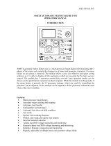
2 INTRODUCTION
This document details the installation and operation requirements of the DSE7110 MKII &
DSE7120 MKII modules, part of the DSE
Genset® range of products.
The manual forms part of the product and should be kept for the entire life of the product. If the
product is passed or supplied to another party, ensure that this document is passed to them for
reference purposes.
This is not a controlled document. You will not be automatically informed of updates. Any future
updates of this document will be included on the DSE website at www.deepseaplc.com
The DSE7xxx series is designed to provide differing levels of functionality across a common
platform. This allows the generator OEM greater flexibility in the choice of controller to use for a
specific application.
The DSE71xx MKII series module has been designed to allow the operator to start and stop the
generator, and if required, transfer the load to the generator either manually or automatically.
Additionally, the DSE7120 MKII automatically starts and stops the generator set depending upon the
status of the mains (utility) supply.
The user also has the facility to view the system operating parameters via the LCD display.
The DSE71xx MKII module monitors the engine, indicating the operational status and fault
conditions, automatically shutting down the engine and giving a true first up fault condition of an
engine failure by the LCD display.
The powerful ARM microprocessor contained within the module allows for incorporation of a range of
complex features:
• Icon based LCD display
• True RMS Voltage
• Current and Power monitoring
• USB Communications
• Engine parameter monitoring.
• Fully configurable inputs for use as alarms or a range of different functions.
• Engine ECU interface to electronic engines.
Using a PC and the DSE Configuration Suite software allows alteration of selected operational
sequences, timers, alarms and operational sequences. Additionally, the module’s integral front panel
configuration editor allows adjustment of this information.
A robust plastic case designed for front panel mounting houses the module. Connections are via
locking plug and sockets.
Access to critical operational sequences and timers for use by qualified engineers, can be protected
by a security code. Module access can also be protected by PIN code. Selected parameters can be
changed from the module’s front panel.
The module is housed in a robust plastic case suitable for panel mounting. Connections to the
module are via locking plug and sockets.

Specification
9
3 SPECIFICATION
3.1 SHORT NAMES
Short Name Description
DSE7000, DSE7xxx All modules in the DSE7000 range.
DSE7100 MKII, DSE71xx MKII All modules in the DSE7100 MKII range.
DSE7110 MKII DSE7110 MKII module/controller
DSE7120 MKII DSE7120 MKII module/controller
3.2 OPERATING TEMPERATURE
Module Description
DSE71xx MKII -30ºC to +70ºC (-40ºC to +70ºC for display heater variants)
3.3 REQUIREMENTS FOR UL CERTIFICATION
Screw Terminal
Tightening
Torque
• 4.5 lb-in (0.5 Nm)
Conductors
• Terminals suitable for connection of conductor size 12 AWG – 26 AWG
(0.5mm² to 2.0mm²).
• Conductor protection must be provided in accordance with NFPA 70, Article
240
• Low voltage circuits (35 volts or less) must be supplied from the engine
starting battery or an isolated secondary circuit.
• The communication, sensor, and/or battery derived circuit conductors shall be
separated and secured to maintain at least ¼” (6mm) separation from the
generator and mains connected circuit conductors unless all conductors are
rated 600 Volts or greater.
Current Inputs
• Must be connected through UL Listed or Recognized isolating current
transformers with the secondary rating of 5A max.
Communication
Circuits
• Must be connected to communication circuits of UL Listed equipment
Output Pilot Duty
• 0.5 A
Mounting
• Suitable for use in type 1 Enclosure Type rating with surrounding air
temperature -22ºF to +158ºF (-30ºC to +70ºC)
• Suitable for pollution degree 3 environments when voltage sensing inputs do
not exceed 300V. When used to monitor voltages over 300V device to be
install in an unventilated or filtered ventilation enclosure to maintain a pollution
degree 2 environment.
Operating
Temperature
• -22ºF to +158ºF (-30ºC to +70ºC)
Storage
Temperature
• -40ºF to +176ºF (-40ºC to +80ºC)

Specification
10
3.4 TERMINAL SPECIFICATION
NOTE: For purchasing additional connector plugs from DSE, please see the section
entitled Maintenance, Spares, Repair and Servicing elsewhere in this document.
Connection Type
Two part connector.
• Male part fitted to
module
• Female part supplied in
module packing case -
Screw terminal, rising
clamp, no internal
spring.
Example showing cable entry and screw
terminals of a 10 way connector
Minimum Cable Size 0.5mm² (AWG 24)
Maximum Cable Size 2.5mm² (AWG 10)
3.5 POWER SUPPLY REQUIREMENTS
Minimum Supply Voltage 8V continuous
Cranking Dropouts
Able to survive 0V for 100ms providing the supply was at least
10V before the dropout and recovers to 5V afterwards.
Maximum Supply Voltage 35V continuous (60V protection)
Reverse Polarity Protection -35V continuous
Maximum Operating Current
290mA at 12V
140mA at 24V
Maximum Standby Current
75mA at 12V
40mA at 24V
Maximum Current When In
Sleep Mode
40mA at 12V
35mA at 24V
3.5.1 MODULE SUPPLY INSTRUMENTATION DISPLAY
Range 0V-70V DC (note Maximum continuous operating voltage of 35V DC)
Resolution 0.1V
Accuracy 1% full scale (±0.7V)

Specification
11
3.6 VOLTAGE & FREQUENCY SENSING
Measurement Type True RMS conversion
Sample Rate 5kHz or better
Harmonics Up to 11
th
or better
Input Impedance
300kΩ phase to neutral
Phase To Neutral
15V
(minimum required for sensing frequency
)
to 415V AC
(absolute maximum)
Suitable for 345V AC nominal
(±20% for under/overvoltage detection)
Phase To Phase
25V
(minimum required for sensing frequency
)
to 720V AC
(absolute maximum)
Suitable for 600V AC nominal
(±20% for under/overvoltage detection)
Common Mode Offset From Earth 100V AC (max)
Resolution
1V AC phase to neutral
2V AC phase to phase
Accuracy
±1% of full scale phase to neutral
±2% of full scale phase to phase
Minimum Frequency 3.5 Hz
Maximum Frequency 75.0 Hz
Frequency Resolution 0.1 Hz
Frequency Accuracy ±0.2 Hz
3.7 CURRENT SENSING
Measurement Type True RMS conversion
Sample Rate 5KHz or better
Harmonics Up to 10
th
or better
Nominal CT Secondary Rating 5A
Maximum Continuous Current 5A
Overload Measurement 3 x Nominal Range setting
Absolute Maximum Overload 50A for 1 second
Burden
0.25VA (0.01Ω current shunts)
Common Mode Offset ±1V peak plant ground to CT common terminal
Resolution 0.5% of 5A
Accuracy ±1% of Nominal (5A) (excluding CT error)

Specification
12
3.7.1 VA RATING OF THE CTS
The VA burden of the module on the CTs is 0.5VA. However depending upon the type and length of
cabling between the CTs and the module, CTs with a greater VA rating than the module are required.
The distance between the CTs and the
measuring module should be
estimated and cross-referenced
against the chart opposite to find the
VA burden of the cable itself.
If the CTs are fitted within the
alternator top box, the star point
(common) of the CTs should be
connected to system ground (earth) as
close as possible to the CTs. This
minimises the length of cable used to
connect the CTs to the DSE module.
Example.
If 1.5mm² cable is used and the
distance from the CT to the measuring
module is 20m, then the burden of the
cable alone is approximately 15VA. As
the burden of the DSE controller is
0.5VA, then a CT with a rating of at
least 15+0.5V = 15.5VA must be used.
If 2.5mm² cables are used over the
same distance of 20m, then the
burden of the cable on the CT is
approximately 7VA. CT’s required in
this instance is at least 7.5VA (7+0.5).
NOTE: Details for 4mm² cables are shown for reference only. The connectors on the DSE
modules are only suitable for cables up to 2.5mm².

Specification
13
3.7.2 CT POLARITY
NOTE: Take care to ensure correct polarity of the CT primary as shown above. If in doubt,
check with the CT supplier.
Take care to ensure the correct polarity of the CTs. Incorrect CT orientation leads to negative kW
readings when the set is supplying power. Take note that paper stick-on labels on CTs that show the
orientation are often incorrectly placed on the CT (!). It is more reliable to use the labelling in the
case moulding as an indicator to orientation (if available).
To test orientation, run the generator in island mode (not in parallel with any other supply) and load
the generator to around 10% of the set rating. Ensure the DSE module shows positive kW for all
three individual phase readings.
TO GENERATOR
TO LOAD
POLARITY OF CT PRIMARY
3.7.3 CT PHASING
Take particular care that the CTs are connected to the correct phases. For instance, ensure that the
CT on phase 1 is connected to the terminal on the DSE module intended for connection to the CT for
phase 1.
Additionally ensure that the voltage sensing for phase 1 is actually connected to generator phase 1.
Incorrect connection of the phases as described above results in incorrect power factor (pf)
measurements, which in turn results in incorrect kW measurements.
One way to check for this is to make use of a single-phase load. Place the load on each phase in
turn, run the generator and ensure the kW value appears in the correct phase. For instance if the
load is connected to phase 3, ensure the kW figure appears in phase 3 display and not in the display
for phase 1 or 2.
3.7.4 CT CLASS
Ensure the correct CT type is chosen. For instance if the DSE module is providing overcurrent
protection, ensure the CT is capable of measuring the overload level you wish to protect against, and
at the accuracy level you require.
For instance, this may mean fitting a protection class CT (P10 type) to maintain high accuracy while
the CT is measuring overload currents.
Conversely, if the DSE module is using the CT for instrumentation only (current protection is disabled
or not fitted to the controller), then measurement class CTs can be used. Again, bear in mind the
accuracy you require. The DSE module is accurate to better than 1% of the full-scale current reading.
To maintain this accuracy you should fit Class 0.5 or Class 1 CTs.
You should check with your CT manufacturer for further advice on selecting your CTs
Labelled as
p1,
k
or K
Labelled as
p2,
l
or L

Specification
14
3.8 INPUTS
3.8.1 DIGITAL INPUTS
Number
6 configurable digital inputs
(10 when Analogue Inputs are configured as digital inputs)
Arrangement Contact between terminal and ground
Low Level Threshold 3.2V minimum
High Level Threshold 8.1V maximum
Maximum Input Voltage +60V DC with respect to plant supply negative
Minimum Input Voltage -24V DC with respect to plant supply negative
Contact Wetting Current 6mA typical
Open Circuit Voltage 15V typical
3.8.2 ANALOGUE INPUTS
3.8.2.1 OIL PRESSURE
Measurement Type
Resistance measurement by measuring voltage across sensor with a
fixed current applied
Arrangement Differential resistance measurement input
Measurement Current 11mA ±10%
Full Scale
240Ω
Over Range / Fail
270Ω
Resolution 0.1 Bar (1-2 PSI)
Accuracy
±2% of full scale resistance (±4.8Ω) excluding transducer error
Max Common Mode Voltage ±2V
Display Range 0 bar - 17.2 bar (0PSI - 250PSI) subject to limits of the sensor
3.8.2.2 COOLANT TEMPERATURE
Measurement Type
Resistance measurement by measuring voltage across sensor with a
fixed current applied
Arrangement Differential resistance measurement input
Measurement Current 11mA ±10%
Full Scale
480Ω
Over Range / Fail
540Ω
Resolution
1°C (2°F)
Accuracy
+/-2% of full scale resistance (±9.6Ω) excluding transducer error
Max Common Mode Voltage ±2V
Display Range
0°C - 250°C (32°F - 482°F) subject to limits of the sensor

Specification
15
3.8.2.3 FUEL LEVEL SENSOR
Measurement Type
Resistance measurement by measuring voltage across sensor with
a fixed current applied
Arrangement Differential resistance measurement input
Measurement Current 11mA ±10%
Full Scale
480Ω
Over Range / Fail
540Ω
Resolution 1%
Accuracy
+/-2% of full scale resistance (±9.6Ω) excluding transducer error
Max Common Mode Voltage ±2V
Display Range 0% - 250% subject to limits of the sensor
3.8.2.4 FLEXIBLE SENSOR
Number 2 when Fuel Level Sender is configured as a flexible
Measurement Type
Resistance measurement by measuring voltage across sensor with
a fixed current applied
Arrangement Differential resistance measurement input
Measurement Current 11mA ±10%
Full Scale
480Ω
Over Range / Fail
540Ω
Resolution 1%
Accuracy
+/-2% of full scale resistance (±9.6Ω) excluding transducer error
Max Common Mode Voltage ±2V
Display Range
0% - 250%, 0°C - 250°C (32°F - 482°F) or 0 bar - 17.2 bar (0PSI -
250PSI)subject to limits of the sensor and sensor configuration
3.8.3 CHARGE FAIL INPUT
Minimum Voltage 0V
Maximum Voltage 35V (plant supply)
Resolution 0.2V
Accuracy ± 1% of max measured voltage
Excitation Active circuit constant power output
Output Power 2.5W nominal at 12V and 24V
Current At 12V 210mA
Current At 24V 105mA
The charge fail input is actually a combined input and output. Whenever the generator is required to
run, the terminal provides excitation current to the charge alternator field winding.
When the charge alternator is correctly charging the battery, the voltage of the terminal is close to
the plant battery supply voltage. In a failed charge situation, the voltage of this terminal is pulled
down to a low voltage. It is this drop in voltage that triggers the charge failure alarm. The level at
which this operates and whether this triggers a warning or shutdown alarm is configurable using the
DSE Configuration Suite Software.

Specification
16
3.8.4 MAGNETIC PICKUP
Type Differential input
Minimum Voltage 0.5V RMS
Max Common Mode Voltage ±2V
Maximum Voltage
Clamped to ±70V by transient suppressers, dissipation not to
exceed1W.
Maximum Frequency 10,000 Hz
Resolution 6.25 RPM
Accuracy ±25 RPM
Flywheel Teeth 10 to 500
NOTE: DSE can supply a suitable magnetic pickup device, available in two body thread
lengths:
DSE Part number 020-012 - Magnetic Pickup probe 5/8 UNF 2½” thread length
DSE Part number 020-013 - Magnetic Pickup probe 5/8 UNF 4” thread length
Magnetic Pickup devices can often be ‘shared’ between two or more devices. For example, one
device can often supply the signal to both the DSE module and the engine governor. The possibility
of this depends upon the amount of current that the magnetic pickup can supply.
3.9 OUTPUTS
3.9.1 DC OUTPUTS A & B (FUEL & START)
Type
Normally used as Fuel & Start outputs.
Fully configurable for other purposes if the module is configured to control an
electronic engine.
Rating 10A resistive for 10secs, 5A resistive continuous at plant supply.
3.9.2 CONFIGURABLE VOLT-FREE OUTPUTS C & D
Type Normally used for load switching control
Fully configurable volt-free relays. One normally open and one normal closed.
Rating 8A resistive at 250 V AC
3.9.3 CONFIGURABLE DC OUTPUTS E, F, G & H
Type Fully configurable, supplied from DC supply terminal 2.
Rating 2A resistive continuous at plant supply.

Specification
17
3.10 COMMUNICATION PORTS
USB Port
USB 2.0 Device for connection to PC running DSE configuration suite only.
Max distance 6m (18 yards)
CAN Port
Engine CAN Port
Standard implementation of ‘Slow mode’, up to 250K bits/s
Non-Isolated.
Internal Termination provided (120Ω)
Max distance 40m (133 feet)
NOTE: For additional length, the DSE124 CAN Extender is available. For
more information, refer to DSE Publication: 057-116 DSE124 Operator Manual
3.10.1 COMMUNICATION PORT USAGE
3.10.1.1 CAN INTERFACE
Modules are fitted with the CAN interface as standard and are capable of
receiving engine data from engine CAN controllers compliant with the
CAN standard.
CAN enabled engine controllers monitor the engine’s operating
parameters such as engine speed, oil pressure, engine temperature
(among others) in order to closely monitor and control the engine. The industry standard
communications interface (CAN) transports data gathered by the engine controller interface. This
allows generator controllers to access these engine parameters with no physical connection to the
sensor device.
NOTE: For further details on connection to electronic engines, refer to DSE Publication:
057-004 Electronic Engines And DSE Wiring

Specification
18
3.10.1.2 USB CONNECTION
The USB port is provided to give a simple means of connection between a PC and the controller.
Using the DSE Configuration Suite Software, the operator is then able to control the module, starting
or stopping the generator, selecting operating modes, etc.
Additionally, the various operating parameters (such as output volts, oil pressure, etc.) of the remote
generator are available to be viewed or changed.
To connect a module to a PC by USB, the following items are required:
• DSE71xx MKII Controller
• DSE Configuration Suite PC Software
(Supplied on configuration suite software CD or
available from www.deepseaplc.com).
• USB cable Type A to Type B.
(This is the same cable as often used between a
PC and a USB printer)
DSE can supply this cable if required :
PC Configuration interface lead (USB type A –
type B) DSE Part No 016-125
NOTE: The DC supply must be connected to the module for configuration by PC.
NOTE: For further details of module configuration, refer to DSE Publication: 057-185
DSE71xx MKII Configuration Software Manual.

Specification
19
3.11 ADDING AN EXTERNAL SOUNDER
Should an external alarm or indicator be required, this can be achieved by using the DSE
Configuration Suite PC software to configure an auxiliary output for “Audible Alarm”, and by
configuring an auxiliary input for “Alarm Mute” (if required).
The audible alarm output activates and de-activates at the same time as the module’s internal
sounder. The Alarm mute input and internal Lamp Test / Alarm Mute
button activate ‘in parallel’
with each other. Either signal mutes the internal sounder and audible alarm output.
Example of configuration to achieve external sounder with external alarm mute button:
3.12 ACCUMULATED INSTRUMENTATION
NOTE: When an accumulated instrumentation value exceeds the maximum number as
listed below, it resets and begin counting from zero again.
Engine Hours Run
Maximum 99999 hrs 59 minutes
(Approximately 11yrs 4months)
Accumulated Power 999999 kWh / kVArh / kVAh
The number of logged Engine Hours and Number of Starts can be set/reset using the DSE
Configuration Suite PC software. Depending upon module configuration, this may have been PIN
number locked by your generator supplier

Specification
20
3.13 DIMENSIONS AND MOUNTING
3.13.1 DIMENSIONS
240 mm x 181 mm x 42 mm
(9.4” x 7.1” x 1.6”)
3.13.2 PANEL CUTOUT
220 mm x 160 mm
(8.7” x 6.3”)
3.13.3 WEIGHT
0.7 kg
(1.4 lb)
/