Page is loading ...

057-254 ISSUE: 2
DEEP SEA ELECTRONICS PLC
DSE8610 MKII Operator Manual
Document Number: 057-254
Author: Mark Graham

DSE8610 MKII Operator Manual
057-254 ISSUE: 2 Page 2 of 188
Deep Sea Electronics Plc
Highfield House
Hunmanby
North Yorkshire
YO14 0PH
ENGLAND
Sales Tel: +44 (0) 1723 890099
Sales Fax: +44 (0) 1723 893303
E-mail: sales@deepseaplc.com
Website: www.deepseaplc.com
DSE8610 MKII Operator Manual
© Deep Sea Electronics Plc
All rights reserved. No part of this publication may be reproduced in any material form (including
photocopying or storing in any medium by electronic means or other) without the written permission of
the copyright holder except in accordance with the provisions of the Copyright, Designs and Patents
Act 1988.
Applications for the copyright holder’s written permission to reproduce any part of this publication
must be addressed to Deep Sea Electronics Plc at the address above.
The DSE logo and the names DSEGenset
®
, DSEAts
®
and DSEPower
®
are UK registered trademarks
of Deep Sea Electronics PLC.
Any reference to trademarked product names used within this publication is owned by their respective
companies.
Deep Sea Electronics Plc reserves the right to change the contents of this document without prior
notice.
Amendments Since Last Publication
Amd. No.
Comments
1 Initial Release
2 Added information about electrical trip reset

DSE8610 MKII Operator Manual
Page 3 of 188 057-254 ISSUE: 2
TABLE OF CONTENTS
Section Page
1
INTRODUCTION .................................................................................................. 8
1.1
CLARIFICATION OF NOTATION ............................................................................................ 9
1.2
GLOSSARY OF TERMS .......................................................................................................... 9
1.3
BIBLIOGRAPHY .................................................................................................................... 11
1.3.1
INSTALLATION INSTRUCTIONS ................................................................................... 11
1.3.2
MANUALS ....................................................................................................................... 11
1.3.3
TRAINING GUIDES ........................................................................................................ 12
1.3.4
THIRD PARTY DOCUMENTS ........................................................................................ 12
2
SPECIFICATION ................................................................................................ 13
2.1
OPERATING TEMPERATURE .............................................................................................. 13
2.1.1
SCREEN HEATER OPERATION .................................................................................... 13
2.2
REQUIREMENTS FOR UL .................................................................................................... 13
2.3
TERMINAL SPECIFICATION ................................................................................................ 14
2.4
POWER SUPPLY REQUIREMENTS ..................................................................................... 14
2.4.1
MODULE SUPPLY INSTRUMENTATION DISPLAY ...................................................... 14
2.5
VOLTAGE & FREQUENCY SENSING .................................................................................. 15
2.6
CURRENT SENSING ............................................................................................................. 15
2.6.1
VA RATING OF THE CTS ............................................................................................... 16
2.6.2
CT POLARITY ................................................................................................................. 17
2.6.3
CT PHASING ................................................................................................................... 17
2.6.4
CT CLASS ....................................................................................................................... 17
2.7
INPUTS ................................................................................................................................... 18
2.7.1
DIGITAL INPUTS ............................................................................................................ 18
2.7.2
EMERGENCY STOP ...................................................................................................... 18
2.7.3
ANALOGUE INPUTS ...................................................................................................... 19
2.7.3.1
ANALOGUE INPUT A .............................................................................................. 19
2.7.3.2
ANALOGUE INPUT B, C & D .................................................................................. 20
2.7.4
CHARGE FAIL INPUT ..................................................................................................... 21
2.7.5
MAGNETIC PICK-UP ...................................................................................................... 21
2.8
OUTPUTS ............................................................................................................................... 22
2.8.1
DC OUTPUTS A & B (FUEL & START) .......................................................................... 22
2.8.2
CONFIGURABLE VOLT-FREE RELAY OUTPUTS C & D ............................................. 22
2.8.3
CONFIGURABLE DC OUTPUTS E, F, G, H, I, J, K & L ................................................. 22
2.8.4
GOVERNOR CONTROL OUTPUT ................................................................................. 22
2.8.5
AVR CONTROL OUTPUT ............................................................................................... 22
2.9
COMMUNICATION PORTS ................................................................................................... 23
2.10
COMMUNICATION PORT USAGE .................................................................................... 24
2.10.1
USB SLAVE PORT (PC CONFIGURATION) .................................................................. 24
2.10.1.1
USB HOST PORT (DATA LOGGING) ..................................................................... 24
2.10.2
RS232 PORT ................................................................................................................... 25
2.10.2.1
RECOMMENDED EXTERNAL MODEMS ............................................................... 25
2.10.2.2
RECOMMENDED PC RS232 SERIAL PORT ADD-ONS ....................................... 26
2.10.3
RS485 PORT ................................................................................................................... 27
2.10.3.1
CABLE SPECIFICATION ......................................................................................... 27
2.10.3.2
RECOMMENDED PC RS485 SERIAL PORT ADD-ONS ....................................... 28
2.10.3.3
RS485 USED FOR MODBUS ENGINE CONNECTION ......................................... 29
2.10.4
ETHERNET PORT .......................................................................................................... 30
2.10.4.1
DIRECT PC CONNECTION ..................................................................................... 31
2.10.4.2
CONNECTION TO BASIC ETHERNET ................................................................... 32
2.10.4.3
CONNECTION TO COMPANY ETHERNET INFRASTRUCTURE ......................... 33
2.10.4.4
CONNECTION TO THE INTERNET ........................................................................ 34
2.10.4.5
FIREWALL CONFIGURATION FOR INTERNET ACCESS .................................... 35
2.10.5
MSC (MULTI-SET COMMUNICATIONS) LINK .............................................................. 36
2.10.7
CAN PORT ...................................................................................................................... 37
2.10.8
ECU PORT (J1939) ......................................................................................................... 37

DSE8610 MKII Operator Manual
057-254 ISSUE: 2 Page 4 of 188
2.10.9
DSENET
®
(EXPANSION MODULES) ............................................................................. 38
2.10.9.1
DSENET
®
USED FOR MODBUS ENGINE CONNECTION .................................... 39
2.11
SOUNDER .......................................................................................................................... 40
2.11.1
ADDING AN EXTERNAL SOUNDER ............................................................................. 40
2.12
ACCUMULATED INSTRUMENTATION ............................................................................ 40
2.13
DIMENSIONS AND MOUNTING ........................................................................................ 41
2.13.1
DIMENSIONS .................................................................................................................. 41
2.13.2
PANEL CUTOUT ............................................................................................................. 41
2.13.3
WEIGHT .......................................................................................................................... 41
2.13.4
FIXING CLIPS ................................................................................................................. 42
2.13.5
CABLE TIE FIXING POINTS ........................................................................................... 43
2.13.6
SILICON SEALING GASKET .......................................................................................... 43
2.14
APPLICABLE STANDARDS ............................................................................................. 44
2.14.1
ENCLOSURE CLASSIFICATIONS ................................................................................. 46
2.14.1.1
IP CLASSIFICATIONS ............................................................................................. 46
2.14.1.2
NEMA CLASSIFICATIONS ...................................................................................... 46
3
INSTALLATION ................................................................................................. 47
3.1
USER CONNECTIONS .......................................................................................................... 47
3.2
CONNECTION DESCRIPTIONS ........................................................................................... 48
3.2.1
DC SUPPLY, E-STOP INPUT, DC OUTPUTS & CHARGE FAIL INPUT ....................... 48
3.2.2
ANALOGUE SENSOR INPUTS & CAN .......................................................................... 49
3.2.3
MPU, ECU, MSC & DSENET
®
........................................................................................ 50
3.2.4
OUTPUT C & D & V1 (GENERATOR) VOLTAGE & FREQUENCY SENSING ............. 51
3.2.5
V2 (BUS) VOLTAGE & FREQUENCY SENSING ........................................................... 51
3.2.6
CURRENT TRANSFORMERS ........................................................................................ 52
3.2.6.1
CT CONNECTIONS ................................................................................................. 53
3.2.7
DIGITAL INPUTS ............................................................................................................ 53
3.2.8
RS485 .............................................................................................................................. 54
3.2.9
RS232 .............................................................................................................................. 55
3.2.10
USB SLAVE (PC CONFIGURATION) CONNECTOR .................................................... 56
3.2.11
USB HOST (DATA LOGGING) CONNECTOR ............................................................... 56
3.3
TYPICAL WIRING DIAGRAM ................................................................................................ 57
3.3.1
(3 PHASE 4 WIRE) WITH RESTRICTED EARTH FAULT ............................................. 58
3.3.2
EARTH SYSTEMS .......................................................................................................... 59
3.3.2.1
NEGATIVE EARTH .................................................................................................. 59
3.3.2.2
POSITIVE EARTH ................................................................................................... 59
3.3.2.3
FLOATING EARTH .................................................................................................. 59
3.3.3
TYPICAL ARRANGEMENT OF DSENET
®
..................................................................... 60
3.3.4
TYPICAL ARRANGEMENT OF MSC LINK .................................................................... 61
3.4
ALTERNATE TOPOLOGY WIRING DIAGRAMS ................................................................. 62
3.4.1
SINGLE PHASE (L1 & N) 2 WIRE WITH RESTRICTED EARTH FAULT ...................... 62
3.4.2
SINGLE PHASE (L1 & N) 2 WIRE WITHOUT EARTH FAULT ...................................... 63
3.4.3
SINGLE PHASE (L1 & L2) 3 WIRE WITH RESTRICTED EARTH FAULT..................... 64
3.4.4
SINGLE PHASE (L1 & L2) 3 WIRE WITHOUT EARTH FAULT ..................................... 65
3.4.5
SINGLE PHASE (L1 & L3) 3 WIRE WITH RESTRICTED EARTH FAULT..................... 66
3.4.6
SINGLE PHASE (L1 & L3) 3 WIRE WITHOUT EARTH FAULT ..................................... 67
3.4.7
2 PHASE (L1 & L2) 3 WIRE WITH RESTRICTED EARTH FAULT ................................ 68
3.4.8
2 PHASE (L1 & L2) 3 WIRE WITHOUT EARTH FAULT ................................................ 69
3.4.9
2 PHASE (L1 & L3) 3 WIRE WITH RESTRICTED EARTH FAULT ................................ 70
3.4.10
2 PHASE (L1 & L3) 3 WIRE WITHOUT EARTH FAULT ................................................ 71
3.4.11
3 PHASE 3 WIRE DETLA WITHOUT EARTH FAULT.................................................... 72
3.4.12
3 PHASE 4 WIRE WITHOUT EARTH FAULT ................................................................ 73
3.4.13
3 PHASE 4 WIRE WITH RESTRICTED EARTH FAULT ................................................ 74
3.4.14
3 PHASE 4 WIRE WITH UNRESTRICTED EARTH FAULT .......................................... 75
3.5
TYPICAL SINGLE LINE APPLICATION DRAWINGS .......................................................... 76
3.5.1
MULTI GENERATORS FOR PRIME POWER ................................................................ 76
3.5.2
MULTI GENERATORS FOR PRIME POWER WITH BUS COUPLERS ........................ 77
3.5.3
MULTI GENERATORS WITH SINGLE SYNCHRONISING TRANSFER SWITCH ....... 78
3.5.4
MULTI GENERATORS WITH TWO SYNCHRONISING TRANSFER SWITCHES ....... 79

DSE8610 MKII Operator Manual
Page 5 of 188 057-254 ISSUE: 2
3.5.5
MULTI GENERATORS & SYNCHRONISING TRANSFER SWITCHES ........................ 80
3.5.6
MULTI GENERATORS & TRANSFER SWITCHES WITH BUS COUPLER .................. 81
3.5.7
SINGLE GENERATOR EXPORTING (BASE LOADING) POWER ................................ 82
3.5.8
MULTI GENERATORS EXPORTING (BASE LOADING) POWER ................................ 83
4
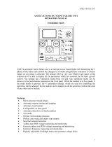
DESCRIPTION OF CONTROLS ........................................................................ 84
4.1
CONTROL PUSH BUTTONS ................................................................................................ 86
4.2
VIEWING THE INSTRUMENT PAGES .................................................................................. 88
4.2.1
STATUS .......................................................................................................................... 89
4.2.1.1
GENERATOR LOCKED OUT .................................................................................. 90
4.2.1.2
WAITING FOR GENERATOR ................................................................................. 90
4.2.2
ENGINE ........................................................................................................................... 91
4.2.2.1
MANUAL FUEL PUMP CONTROL .......................................................................... 92
4.2.2.2
DPF REGENERATION LAMPS ............................................................................... 93
4.2.3
GENERATOR .................................................................................................................. 94
4.2.3.1
COMMISIONING SCREENS ................................................................................... 95
4.2.3.2
SYNCHROSCOPE ................................................................................................... 96
4.2.4
BUS ................................................................................................................................. 96
4.2.5
EXPANSION .................................................................................................................... 97
4.2.6
ALARMS .......................................................................................................................... 98
4.2.6.1
ECU ALARMS (CAN FAULT CODES / DTC) .......................................................... 99
4.2.7
EVENT LOG .................................................................................................................. 100
4.2.7.1
PROTECTIONS DISABLED .................................................................................. 101
4.2.7.2
RESET ELECTRICAL TRIP ................................................................................... 101
4.2.8
SERIAL PORT ............................................................................................................... 102
4.2.8.1
RS232 SERIAL PORT ........................................................................................... 102
4.2.8.2
RS485 SERIAL PORT ........................................................................................... 106
4.2.9
ABOUT .......................................................................................................................... 107
4.2.9.1
MODULE INFORMATION ...................................................................................... 107
4.2.9.2
ETHERNET ............................................................................................................ 108
4.2.9.3
DATA LOGGING .................................................................................................... 109
4.3
USER CONFIGURABLE INDICATORS .............................................................................. 110
5
OPERATION .................................................................................................... 111
5.1
QUICKSTART GUIDE .......................................................................................................... 111
5.1.1
STARTING THE ENGINE ............................................................................................. 111
5.1.2
STOPPING THE ENGINE ............................................................................................. 112
5.2
STOP/RESET MODE ........................................................................................................... 113
5.2.1
ECU OVERRIDE ........................................................................................................... 113
5.3
MANUAL MODE .................................................................................................................. 114
5.3.1
STARTING SEQUENCE ............................................................................................... 114
5.3.2
ENGINE RUNNING ....................................................................................................... 115
5.3.3
STOPPING SEQUENCE ............................................................................................... 115
5.4
AUTOMATIC MODE ............................................................................................................ 116
5.4.1
WAITING IN AUTO MODE ............................................................................................ 116
5.4.2
STARTING SEQUENCE ............................................................................................... 117
5.4.3
ENGINE RUNNING ....................................................................................................... 118
5.4.4
STOPPING SEQUENCE ............................................................................................... 118
5.5
SCHEDULER ....................................................................................................................... 119
5.5.1
STOP MODE ................................................................................................................. 119
5.5.2
MANUAL MODE ............................................................................................................ 119
5.5.3
AUTO MODE ................................................................................................................. 119
5.6
MSC COMPATIBILITY MODE ............................................................................................. 120
5.7
ALTERNATIVE CONFIGURATIONS ................................................................................... 121
5.8
DUMMY LOAD / LOAD SHEDDING CONTROL ................................................................. 121
5.8.1
DUMMY LOAD CONTROL ........................................................................................... 121
5.8.2
LOAD SHEDDING CONTROL ...................................................................................... 122
5.9
SMS CONTROL ................................................................................................................... 123
5.10
DEAD BUS SYNCHRONISING (AUTO MODE) .............................................................. 124
5.10.1
BENEFIT OF SYSTEM ................................................................................................. 124
5.10.2
HARDWARE REQUIREMENTS ................................................................................... 124

DSE8610 MKII Operator Manual
057-254 ISSUE: 2 Page 6 of 188
5.10.3
OPERATION ................................................................................................................. 125
6
PROTECTIONS ............................................................................................... 126
6.1
ALARMS .............................................................................................................................. 126
6.1.1
PROTECTIONS DISABLED .......................................................................................... 127
6.1.2
RESET ELECTRICAL TRIP .......................................................................................... 128
6.1.3
ECU ALARMS (CAN FAULT CODES / DTC) ............................................................... 129
6.2
INDICATIONS ...................................................................................................................... 130
6.3
WARNING ALARMS ............................................................................................................ 131
6.4
ELECTRICAL TRIP ALARMS ............................................................................................. 137
6.5
SHUTDOWN ALARMS ........................................................................................................ 143
6.6
MAINTENANCE ALARMS ................................................................................................... 149
6.7
OVER CURRENT ALARM ................................................................................................... 151
6.7.1
IMMEDIATE WARNING ................................................................................................ 151
6.7.2
INVERSE DEFINITE MINIMUM TIME (IDMT) ALARM................................................. 152
6.7.2.1
CREATING A SPREADSHEET FOR THE OVER CURRENT IDMT CURVE ....... 153
6.8
SHORT CIRCUIT IDMT ALARM .......................................................................................... 155
6.8.1
CREATING A SPREADSHEET FOR THE SHORT CIRCUIT IDMT CURVE ............... 156
6.9
EARTH FAULT IDMT ALARM ............................................................................................. 158
6.9.1
CREATING A SPREADSHEET FOR THE EARTH FAULT IDMT CURVE .................. 159
6.10
DEFAULT CURRENT PROTECTION TRIPPING CHARACTERISTICS ........................ 161
7
FRONT PANEL CONFIGURATION ................................................................. 163
7.1
MAIN CONFIGURATION EDTIOR ...................................................................................... 164
7.1.1
ACESSING THE MAIN CONFIGURATION EDTIOR .................................................... 164
7.1.2
ENTERING PIN ............................................................................................................. 164
7.1.3
EDITING A PARAMETER ............................................................................................. 165
7.1.4
EXITING THE MAIN CONFIGURATION EDITOR ........................................................ 165
7.1.5
ADJUSTABLE PARAMETERS ..................................................................................... 166
7.2
‘RUNNING’ CONFIGURATION EDITOR ............................................................................. 168
7.2.1
ACCESSING THE ‘RUNNING’ CONFIGURATION EDITOR ....................................... 168
7.2.2
ENTERING PIN ............................................................................................................. 168
7.2.3
EDITING A PARAMETER ............................................................................................. 168
7.2.4
EXITING THE ‘RUNNING’ CONFIGURATION EDITOR .............................................. 169
7.2.5
RUNNING EDITOR PARAMETERS ............................................................................. 169
8
COMMISIONING .............................................................................................. 170
8.1
BASIC CHECKS .................................................................................................................. 170
8.2
DSE 4 STEPS TO SUCCESSFUL SYNCHRONISING ....................................................... 171
8.2.1
CONTROL ..................................................................................................................... 172
8.2.1.1
DETERMINING CONNECTIONS AND SETTINGS FOR GOVERNORS ............. 172
8.2.1.2
DETERMINING CONNECTIONS AND SETTINGS FOR AVRS ........................... 174
8.2.2
METERING .................................................................................................................... 176
8.2.2.1
CTS ON THE RIGHT PHASE ................................................................................ 176
8.2.2.2
CTS IN THE RIGHT DIRECTION .......................................................................... 176
8.2.3
COMMUNICATIONS ..................................................................................................... 177
8.2.4
SYNC CHECKS............................................................................................................. 178
8.2.4.1
INCORRECTLY WIRED BREAKER ...................................................................... 179
8.2.4.2
CORRECTLY WIRED BREAKER .......................................................................... 180
9
FAULT FINDING .............................................................................................. 181
9.1
STARTING ........................................................................................................................... 181
9.2
LOADING ............................................................................................................................. 181
9.3
ALARMS .............................................................................................................................. 182
9.4
COMMUNICATIONS ............................................................................................................ 182
9.5
INSTRUMENTS .................................................................................................................... 182
9.6
SYNCHRONISING & LOAD SHARING ............................................................................... 183
9.7
MISCELLANEOUS ............................................................................................................... 183
10
MAINTENANCE, SPARES, REPAIR AND SERVICING .............................. 184
10.1
PURCHASING ADDITIONAL CONNECTOR PLUGS FROM DSE ................................. 184
10.1.1
PACK OF PLUGS ......................................................................................................... 184

DSE8610 MKII Operator Manual
Page 7 of 188 057-254 ISSUE: 2
10.1.2
INDIVIDUAL PLUGS ..................................................................................................... 184
10.2
PURCHASING ADDITIONAL FIXING CLIPS FROM DSE .............................................. 184
10.3
PURCHASING ADDITIONAL SEALING GASKET FROM DSE ..................................... 185
10.4
DSENET
®
EXPANSION MODULES ................................................................................ 185
11
WARRANTY ................................................................................................. 186
12
DISPOSAL .................................................................................................... 186
12.1
WEEE (WASTE ELECTRICAL AND ELECTRONIC EQUIPMENT) ............................... 186

Introduction
057-254 ISSUE: 2 Page 8 of 188
1 INTRODUCTION
This document details the installation and operation requirements of the DSE8610 MKII module and is
part of the DSEGenset® range of products.
The manual forms part of the product and should be kept for the entire life of the product. If the
product is passed or supplied to another party, ensure that this document is passed to them for
reference purposes.
This is not a controlled document. DSE do not automatically inform on updates. Any future updates of
this document are included on the DSE website at www.deepseaplc.com
The DSE86xx MKII series is designed to provide differing levels of functionality across a common
platform. This allows the generator OEM greater flexibility in the choice of controller to use for a
specific application.
The DSE8610 MKII module has been designed to allow the operator to start, stop and synchronise
the generator, and if required, transfer the load to the generator either manually or automatically.
Synchronsing and Load Sharing features are included within the controller, along with the necessary
protections for such a system.
The user also has the facility to view the system operating parameters via the text LCD display.
The DSE8610 MKII module monitors the engine, indicating the operational status and fault conditions,
automatically shutting down the engine and giving a true first up fault condition of an engine failure by
the text LCD display.
The powerful ARM microprocessor contained within the module allows for incorporation of a range of
complex features:
Text based LCD display
True RMS Voltage
Current and Power monitoring
USB, RS232, RS485 and Ethernet Communications
Engine parameter monitoring.
Fully configurable inputs for use as alarms or a range of different functions.
Engine ECU interface to electronic engines including Tier 4 engines.
Synchronising and load sharing with load demand start/stop
Integral PLC to help provide customisation where required
Fuel tank level monitoring to track fuel filling operations and detect fuel leak/theft
Data Logging
Direct connection to governor / AVR for synchronising and load sharing
R.O.C.O.F. and vector shift protection for detection of mains failure when in parallel with the mains.
The DSE Configuration Suite PC Software allows alteration of selected operational sequences,
timers, alarms and operational sequences. Additionally, the module’s integral front panel configuration
editor allows adjustment of this information.
Access to critical operational sequences and timers for use by qualified engineers, can be protected
by a security code. Module access can also be protected by PIN code. Selected parameters can be
changed from the module’s front panel.
The module is housed in a robust plastic case suitable for panel mounting. Connections to the module
are via locking plug and sockets.

Introduction
Page 9 of 188 057-254 ISSUE: 2
1.1 CLARIFICATION OF NOTATION
Clarification of notation used within this publication.
NOTE:
Highlights an essential element of a procedure to ensure correctness.
CAUTION!
Indicates a procedure or practice, which, if not strictly observed, could
result in damage or destruction of equipment.
WARNING!
Indicates a procedure or practice, which could result in injury to personnel
or loss of life if not followed correctly.
1.2 GLOSSARY OF TERMS
Term
Description
DSE8000 MKII,
DSE8xxx MKII
All modules in the DSE8xxx MKII range.
DSE8600 MKII,
DSE86xx MKII
All modules in the DSE86xx MKII range.
DSE8610 MKII DSE8610 MKII module/controller
DSE8x10 DSE8610, DSE8610 MKII, DSE8710 and DSE8810 module/controller
DSE8x60 DSE8660, DSE8660 MKII, DSE8760 and DSE8860 module/controller
DSE8x80 DSE8680 module/controller
CAN Controller Area Network
Vehicle standard to allow digital devices to communicate to one another.
CDMA Code Division Multiple Access.
Cell phone access used in small number of areas including parts of the USA and
Australia.
CT Current Transformer
An electrical device that takes a large AC current and scales it down by a fixed
ratio to a smaller current.
BMS Building Management System
A digital/computer based control system for a building’s infrastructure.
DEF Diesel Exhaust Fluid (AdBlue)
A liquid used as a consumable in the SCR process to lower nitric oxide and
nitrogen dioxide concentration in engine exhaust emissions.
DM1 Diagnostic Message 1
A DTC that is currently active on the engine ECU.
DM2 Diagnostic Message 2
A DTC that was previously active on the engine ECU and has been stored in the
ECU’s internal memory.
DPF Diesel Particulate Filter
A filter fitted to the exhaust of an engine to remove diesel particulate matter or soot
from the exhaust gas.
DPTC Diesel Particulate Temperature Controlled Filter
A filter fitted to the exhaust of an engine to remove diesel particulate matter or soot
from the exhaust gas which is temperature controlled.
DTC Diagnostic Trouble Code
The name for the entire fault code sent by an engine ECU.
ECU/ECM Engine Control Unit/Management
An electronic device that monitors engine parameters and regulates the fuelling.
FMI Failure Mode Indicator
A part of DTC that indicates the type of failure, e.g. high, low, open circuit etc.
Continued over page…

Introduction
057-254 ISSUE: 2 Page 10 of 188
Term
Description
GSM Global System for Mobile communications. Cell phone technology used in most of
the World.
HEST High Exhaust System Temperature
Initiates when DPF filter is full in conjunction with an extra fuel injector in the
exhaust system to burn off accumulated diesel particulate matter or soot.
HMI Human Machine Interface
A device that provides a control and visualisation interface between a human and a
process or machine.
IDMT Inverse Definite Minimum Time
MSC Multi-Set Communication
OC Occurrence Count
A part of DTC that indicates the number of times that failure has occurred.
PGN Parameter Group Number
A CAN address for a set of parameters that relate to the same topic and share the
same transmission rate.
PLC Programmable Logic Controller
A programmable digital device used to create logic for a specific purpose.
SCADA Supervisory Control And Data Acquisition
A system that operates with coded signals over communication channels to
provide control and monitoring of remote equipment
SCR Selective Catalytic Reduction
A process that uses DEF with the aid of a catalyst to convert nitric oxide and
nitrogen dioxide into nitrogen and water to reduce engine exhaust emission.
SIM Subscriber Identity Module.
The small card supplied by the GSM/CDMA provider that is inserted into the cell
phone, GSM modem or DSEGateway device to give GSM/GPRS connection.
SMS Short Message Service
The text messaging service of mobile/cell phones.
SPN Suspect Parameter Number
A part of DTC that indicates what the failure is, e.g. oil pressure, coolant
temperature, turbo pressure etc.

Introduction
Page 11 of 188 057-254 ISSUE: 2
1.3 BIBLIOGRAPHY
This document refers to, and is referred by the following DSE publications which are obtained from
the DSE website: www.deepseaplc.com or by contacting DSE technical support:
support@deepseaplc.com.
1.3.1 INSTALLATION INSTRUCTIONS
Installation instructions are supplied with the product in the box and are intended as a ‘quick start’
guide only.
DSE
Part
Description
053-032 DSE2548 LED Expansion Annunciator Installation Instructions
053-033 DSE2130 Input Expansion Installation Instructions
053-034 DSE2157 Output Expansion Installation Instructions
053-125 DSE2131 Ratio-metric Input Expansion Installation Instructions
053-126 DSE2133 RTD/Thermocouple Input Expansion Installation Instructions
053-134 DSE2152 Ratio-metric Output Expansion Installation Instructions
053-182 DSE8610 MKII Installation Instructions
1.3.2 MANUALS
Product manuals are obtained from the DSE website: www.deepseaplc.com or by contacting DSE
technical support: support@deepseaplc.com.
D
SE
Part
Description
N/A DSEGencom (MODBUS protocol for DSE controllers)
057-004 Electronic Engines and DSE Wiring Guide
057-045
Guide to Synchronising and Load Sharing Part 1
(Usage of DSE Load Share Controllers in synchronisation / load sharing systems.)
057-046 Guide to Synchronising and Load Sharing Part 2 (Governor & AVR Interfacing)
057-047 Load Share System Design and Commissioning Guide
057-082 DSE2130 Input Expansion Operator Manual
057-083 DSE2157 Output Expansion Operator Manual
057-084 DSE2548 Annunciator Expansion Operator Manual
057-139 DSE2131 Ratio-metric Input Expansion Manual
057-140 DSE2133 RTD/Thermocouple Expansion Manual
057-141 DSE2152 Ratio-metric Output Expansion Manual
057-151 DSE Configuration Suite PC Software Installation & Operation Manual
057-175 PLC Programming Guide For DSE Controllers
057-220 Options for Communications with DSE Controllers
057-238 DSE8610 MKII Configuration Suite PC Software Manual

Introduction
057-254 ISSUE: 2 Page 12 of 188
1.3.3 TRAINING GUIDES
Training guides are provided as ‘hand-out’ sheets on specific subjects during training sessions and
contain specific information regarding to that subject.
D
SE
Part
Description
056-001 Four Steps To Synchronising
056-005 Using CTs With DSE Products
056-006 Introduction to Comms
056-010 Over Current Protection
056-011 MSC Link
056-013 Load Demand Scheme
056-018 Negative Phase Sequence
056-019 Earth Fault Protection
056-020 Loss Of Excitation
056-021 Mains Decoupling
056-022 Breaker Control
056-023 Adding New CAN Files
056-024 GSM Modem
056-026 kW, kvar, kVA and pf.
056-029 Smoke Limiting
056-030 Module PIN Codes
056-033 Synchronising Requirements
056-036 Expansion Modules
056-043 Sync Process
056-045 PLC as Load Demand Controller
056-047 Out of Sync and Failed To Close
056-051 Sending DSEGencom Control Keys
056-053 Recommended Modems
056-054 DSE xx10 In Fixed Export
056-055 Alternate Configurations
056/057 SW1 & SW2
056-069 Firmware Update
056-071 DSE8610 Auto Test Manual
056-072 Dead Bus Synchronising
056-075 Adding Language Files
056-076 Reading DSEGencom Alarms
056-079 Reading DSEGencom Status
056-080 MODBUS
056-081 Screen Heaters
056-082 Override Gencomm PLC Example
056-083 Synchronising & Loadsharing
056-086 G59
1.3.4 THIRD PARTY DOCUMENTS
The following third party documents are also referred to:
Reference
Description
ISBN 1-55937-879-4
IEEE Std C37.2-1996 IEEE Standard Electrical Power System Device
Function Numbers and Contact Designations. Institute of Electrical and
Electronics Engineers Inc
ISBN 0-7506-1147-2 Diesel generator handbook. L.L.J. Mahon
ISBN 0-9625949-3-8 On-Site Power Generation. EGSA Education Committee.

Specification
Page 13 of 188 057-254 ISSUE: 2
2 SPECIFICATION
2.1 OPERATING TEMPERATURE
Module
Specification
DSE86xx MKII -30 ºC +70 ºC (-22 ºF +158 ºF )
Display Heater Variants -40 ºC +70 ºC (-40 ºF +158 ºF )
2.1.1 SCREEN HEATER OPERATION
Screen Heater Function
Specification
Turn On When Temperature Falls Below -10 ºC (+14 ºF)
Turn Off When Temperature Rises Above -5 ºC (+23 ºF)
2.2 REQUIREMENTS FOR UL
Description
Specification
Screw Terminal
Tightening Torque
4.5 lb-in (0.5 Nm)
Conductors
Terminals suitable for connection of conductor size 12 AWG to 26 AWG
(0.5 mm² to 2.0 mm²).
Conductor protection must be provided in accordance with NFPA 70,
Article 240
Low voltage circuits (35 V or less) must be supplied from the engine
starting battery or an isolated secondary circuit.
The communication, sensor, and/or battery derived circuit conductors
shall be separated and secured to maintain at least ¼” (6 mm) separation
from the generator and mains connected circuit conductors unless all
conductors are rated 600 V or greater.
Current Inputs
Must be connected through UL Listed or Recognized isolating current
transformers with the secondary rating of 5 A max.
Communication Circuits Must be connected to communication circuits of UL Listed equipment
Output Pilot Duty 0.5 A
Mounting
Suitable for use in type 1 Enclosure Type rating with surrounding air
temperature -22 ºF to +158 ºF (-30 ºC to +70 ºC)
Suitable for pollution degree 3 environments when voltage sensing inputs
do not exceed 300 V. When used to monitor voltages over
300 V device to be installed in an unventilated or filtered ventilation
enclosure to maintain a pollution degree 2 environment.
Operating Temperature -22 ºF to +158 ºF (-30 ºC to +70 ºC)
Storage Temperature -40 ºF to +176 ºF (-40 ºC to +80 ºC)

Specification
057-254 ISSUE: 2 Page 14 of 188
2.3 TERMINAL SPECIFICATION
Description
Specification
Connection Type
Two part connector.
Male part fitted to module
Female part supplied in module
packing case - Screw terminal,
rising clamp, no internal spring.
Example showing cable entry and screw
terminals of a 10 way connector
Minimum Cable Size 0.5 mm² (AWG 24)
Maximum Cable Size 2.5 mm² (AWG 12)
Tightening Torque 0.5 Nm (4.5 lb-in)
Wire Strip Length 7 mm (9/32”)
2.4 POWER SUPPLY REQUIREMENTS
Description
Specification
Minimum Supply Voltage 5 V continuous
Cranking Dropouts
Able to survive 0 V for 100 ms providing the supply was at least
was greater than 5 V for 2 seconds before the dropout and
recovers to 5 V afterwards.
Maximum Supply Voltage 35 V continuous (60 V protection)
Reverse Polarity Protection -35 V continuous
Maximum Operating Current
530 mA at 12 V
280 mA at 24 V
Maximum Standby Current
320 mA at 12 V
120 mA at 24 V
Maximum Current When In Sleep
Mode
140 mA at 12 V
75 mA at 24 V
Typical Power
(Controller On, Heater Off)
3.8 W to 4.1 W
Typical Power
(Controller On, Heater On)
6.8 W to 7.1 W
2.4.1 MODULE SUPPLY INSTRUMENTATION DISPLAY
Description
Specification
Range 0 V to 70 V DC (Maximum continuous operating voltage of 35 V DC)
Resolution 0.1 V
Accuracy 1 % full scale (±0.35 V)

Specification
Page 15 of 188 057-254 ISSUE: 2
2.5 VOLTAGE & FREQUENCY SENSING
Description
Specification
Measurement Type True RMS conversion
Sample Rate 40 kHz
Harmonics Up to 21
st
or better
Input Impedance
300 kΩ phase to neutral
Phase To Neutral
15 V (minimum required for sensing frequency) to 415 V AC
(absolute maximum)
Suitable for 345 V AC nominal
(±20 % for under/overvoltage detection)
Phase To Phase
25 V (minimum required for sensing frequency) to 720 V AC
(absolute maximum)
Suitable for 600 V AC nominal
(±20 % for under/overvoltage detection)
Common Mode Offset From Earth 100 V AC (max)
Resolution
1 V AC phase to neutral
2 V AC phase to phase
Accuracy
±1 % of full scale phase to neutral
±2 % of full scale phase to phase
Minimum Frequency 3.5 Hz
Maximum Frequency 75.0 Hz
Frequency Resolution 0.1 Hz
Frequency Accuracy ±0.05 Hz
2.6 CURRENT SENSING
Description
Specification
Measurement Type True RMS conversion
Sample Rate 40 kHz
Harmonics Up to 21
st
or better
Nominal CT Secondary Rating 1 A and 5 A
Maximum Continuous Current 5 A
Overload Measurement 15 A
Absolute Maximum Overload 50 A for 1 second
Burden
0.5 VA (0.02 Ω current shunts)
Common Mode Offset
70 V peak plant ground to CT common terminal under fault
condition
Resolution 25 mA
Accuracy ±1 % of Nominal (excluding CT error)

Specification
057-254 ISSUE: 2 Page 16 of 188
2.6.1 VA RATING OF THE CTS
NOTE: Details for 4 mm² cables are shown for reference only. The connectors on the DSE
modules are only suitable for cables up to 2.5 mm².
The VA burden of the module on the CTs is 0.5 VA. However depending upon the type and length of
cabling between the CTs and the module, CTs with a greater VA rating than the module are required.
The distance betwe
en the CTs and the
measuring module should be
estimated and cross-referenced
against the chart opposite to find the
VA burden of the cable itself.
If the CTs are fitted within the
alternator top box, the star point
(common) of the CTs should be
connected to system ground (earth) as
close as possible to the CTs. This
minimises the length of cable used to
connect the CTs to the DSE module.
Example:
If 1.5 mm² cable is used and the
distance from the CT to the measuring
module is 20 m, then the burden of the
cable alone is approximately 15 VA.
As the burden of the DSE controller is
.5 VA, then a CT with a rating of at
least 15 VA + 0.5 VA = 15.5 VA must
be used. 0.5 VA, then a CT with a rating of at least 15 VA + 0.5 VA = 15.5 VA must be used. If 2.5
mm² cables are used over the same distance of 20 m, then the burden of the cable on the CT is
approximately 7 VA. CT’s required in this instance is at least 7.5 VA (7 + 0.5).

Specification
Page 17 of 188 057-254 ISSUE: 2
2.6.2 CT POLARITY
NOTE: Take care to ensure correct polarity of the CT primary as shown above. If in doubt,
check with the CT supplier.
Take care to ensure the correct polarity of the CTs. Incorrect CT orientation leads to negative kW
readings when the set is supplying power. Take note that paper stick-on labels on CTs that show the
orientation are often incorrectly placed on the CT. It is more reliable to use the labelling in the case
moulding as an indicator to orientation (if available).
To test orientation, run the generator in island mode (not in parallel with any other supply) and load
the generator to around 10 % of the set rating. Ensure the DSE module shows positive kW for all
three individual phase readings.
To Generator
To Load
Polarity of CT Primary
2.6.3 CT PHASING
Take particular care that the CTs are connected to the correct phases. For instance, ensure that the
CT on phase 1 is connected to the terminal on the DSE module intended for connection to the CT for
phase 1.
Additionally ensure that the voltage sensing for phase 1 is actually connected to generator phase 1.
Incorrect connection of the phases as described above results in incorrect power factor (pf)
measurements, which in turn results in incorrect kW measurements.
One way to check for this is to make use of a single-phase load. Place the load on each phase in turn,
run the generator and ensure the kW value appears in the correct phase. For instance if the load is
connected to phase 3, ensure the kW figure appears in phase 3 display and not in the display for
phase 1 or 2.
2.6.4 CT CLASS
Ensure the correct CT type is chosen. For instance if the DSE module is providing over current
protection, ensure the CT is capable of measuring the overload level required to protect against, and
at the accuracy level required.
For instance, this may mean fitting a protection class CT (P15 type) to maintain high accuracy while
the CT is measuring overload currents.
Conversely, if the DSE module is using the CT for instrumentation only (current protection is disabled
or not fitted to the controller), then measurement class CTs can be used. Again, bear in mind the
accuracy required. The DSE module is accurate to better than 1% of the full-scale current reading. To
maintain this accuracy, fit a Class 0.5 or Class 1 CT.
Check with the CT manufacturer for further advice on selecting CTs.
Labelled as
p1,
k
or K
Labelled as
p2,
l
or L

Specification
057-254 ISSUE: 2 Page 18 of 188
2.7 INPUTS
2.7.1 DIGITAL INPUTS
Description
Specification
Number
12 configurable digital inputs
(16 when Analogue Inputs are configured as digital inputs)
Arrangement Contact between terminal and ground
Low Level Threshold 2.1 V minimum
High Level Threshold 6.6 V maximum
Maximum Input Voltage +50 V DC with respect to plant supply negative
Minimum Input Voltage -24 V DC with respect to plant supply negative
Contact Wetting Current 7 mA typical
Open Circuit Voltage 12 V typical
2.7.2 EMERGENCY STOP
Description
Specification
Arrangement Contact between terminal and module supply positive
Closed Threshold 5 V minimum
Open Threshold 3 V maximum
Maximum Input Voltage
+35 V DC with respect to plant supply negative
(60 V protection for 1 minute)
Minimum Input Voltage -24 V DC with respect to plant supply negative
Open Circuit Voltage 0 V

Specification
Page 19 of 188 057-254 ISSUE: 2
2.7.3 ANALOGUE INPUTS
All of the analogue inputs are flexible within the DSE8610 MKII module
2.7.3.1 ANALOGUE INPUT A
Description
Specification
Input Type
Flexible: Configured for Oil Sensor in the DSE default configuration.
Flexible Options: Not used, Digital Input, Flexible Analogue Oil
Sensor
Flexible Input Selection Pressure Sensor, Percentage Sensor or Temperature Sensor
Flexible Measured Quantity Current, Restive or Voltage
Resistive Configuration
Description
Specification
Measurement Type
Resistance measurement by measuring voltage across sensor with
a fixed current applied
Arrangement Differential resistance measurement input
Measurement Current 15 mA ± 2 mA %
Full Scale
480 Ω
Over Range / Fail
600 Ω
Resolution ±1 % of full scale
Accuracy
±2 % of full scale resistance (±9.6 Ω) excluding sensor error
Max Common Mode Voltage ±2 V
Display Range
0 % to 250 %, 0 °C to 250 °C (32 °F to 482 °F) or 0 bar to 17.2 bar
(0 PSI to 250 PSI) subject to limits of the sensor and sensor
configuration
0 V to 10 V Configuration
Description
Specification
Full Scale 0 V to 10 V
Over Range / Fail 11 V
Resolution ±1% of full scale
Accuracy ±2% of full scale voltage (±0.2 V) excluding sensor error
Max Common Mode Voltage ±2 V
Display Range
0 % to 250 %, 0 °C to 250 °C (32 °F to 482 °F) or 0 bar to 17.2 bar
(0 PSI to 250 PSI) subject to limits of the sensor and sensor
configuration
4 mA to 20 mA Configuration
Description
Specification
Full Scale 0 mA to 20 mA
Over Range / Fail 22 mA
Resolution 1% of full scale
Accuracy ±2% of full scale current (±0.4 mA) excluding sensor error
Max Common Mode Voltage ±2 V
Display Range
0 % to 250 %, 0 °C to 250 °C (32 °F to 482 °F) or 0 bar to 17.2 bar
(0 PSI to 250 PSI) subject to limits of the sensor and sensor
configuration

Specification
057-254 ISSUE: 2 Page 20 of 188
2.7.3.2 ANALOGUE INPUT B, C & D
Description
Specification
Analogue Input B Type
Flexible: Configured for Temperature Sensor in the DSE default
configuration.
Flexible Options: Not used, Digital Input and Flexible Analogue
Analogue Input C Type
Flexible: Configured for Fuel Sensor in the DSE default
configuration.
Flexible Options: Not used, Digital Input and Flexible Analogue
Analogue Input D Type
Flexible: Configured for Flexible Analogue in the DSE default
configuration.
Flexible Options: Not used, Digital Input and Flexible Analogue
Flexible Input Selection Pressure Sensor, Percentage Sensor or Temperature Sensor
Flexible Measured Quantity Current, Restive or Voltage
Resistive Configuration
Description
Specification
Measurement Type
Resistance measurement by measuring voltage across sensor with
a fixed current applied
Arrangement Differential resistance measurement input
Measurement Current 15 mA ±10 %
Full Scale
480 Ω
Over Range / Fail
600 Ω
Resolution ±1 % of full scale
Accuracy
±2 % of full scale resistance (±9.6 Ω) excluding sensor error
Max Common Mode Voltage ±2 V
Display Range
0 % to 250 %, 0 °C to 250 °C (32 °F to 482 °F) or 0 bar to 17.2 bar
(0 PSI to 250 PSI) subject to limits of the sensor and sensor
configuration
0 V to 10 V Configuration
Description
Specification
Full Scale 0 V to 10 V
Over Range / Fail 11 V
Resolution ±1% of full scale
Accuracy ±2% of full scale voltage (±0.2 V) excluding sensor error
Max Common Mode Voltage ±2 V
Display Range
0 % to 250 %, 0 °C to 250 °C (32 °F to 482 °F) or 0 bar to 17.2 bar
(0 PSI to 250 PSI) subject to limits of the sensor and sensor
configuration
4 mA to 20 mA Configuration
Description
Specification
Full Scale 0 mA to 20 mA
Over Range / Fail 22 mA
Resolution ±1% of full scale
Accuracy ±2% of full scale current (±0.4 mA) excluding sensor error
Max Common Mode Voltage ±2 V
Display Range
0 % to 250 %, 0 °C to 250 °C (32 °F to 482 °F) or 0 bar to 17.2 bar
(0 PSI to 250 PSI) subject to limits of the sensor and sensor
configuration
/