Page is loading ...

DSE Model 560 Automatic Start Engine Management and Instrumentation System Operators Manual
560 OPERATING MANUAL ISSUE 5 4/4/02 MR 1
MODEL 560
OPERATING MANUAL
Author:- Miles Revell
Deep Sea Electronics Plc
Highfield House
Hunmanby
North Yorkshire
YO14 OPH
England
Tel: +44 (0) 1723 890099
Fax: +44 (0) 1723 893303
E-Mail: [email protected]

DSE Model 560 Automatic Start Engine Management and Instrumentation System Operators Manual
560 OPERATING MANUAL ISSUE 5 4/4/02 MR
2
<<< THIS PAGE INTENTIONALLY BLANK >>>
<<< THIS PAGE INTENTIONALLY BLANK >>><<< THIS PAGE INTENTIONALLY BLANK >>>
<<< THIS PAGE INTENTIONALLY BLANK >>>

DSE Model 560 Automatic Start Engine Management and Instrumentation System Operators Manual
560 OPERATING MANUAL ISSUE 5 4/4/02 MR 3
TABLE OF CONTENTS
Section Page
INTRODUCTION................................................................................................................................5
CLARIFICATION OF NOTATION USED WITHIN THIS PUBLICATION. ......................................5
1. OPERATION ..................................................................................................................................6
1.1 CONTROL ................................................................................................................................6
FIG 1....................................................................................................................................6
1.2 AUTOMATIC MODE OF OPERATION.....................................................................................7
1.3 MANUAL OPERATION.............................................................................................................8
MANUAL OPERATION WITH EXTERNAL START AND STOP PUSHBUTTONS....................9
2. PROTECTIONS............................................................................................................................10
2.1 WARNINGS............................................................................................................................11
2.2 SHUTDOWNS........................................................................................................................ 12
2.3 ELECTRICAL TRIPS..............................................................................................................14
2.4 SPECIAL ALARM CONDITIONS............................................................................................14
3. DECRIPTION OF CONTROLS....................................................................................................15
FIG2...................................................................................................................................15
3.1 TYPICAL LCD DISPLAY SCREENS...................................................................................... 15
LCD DISPLAY AREAS..................................................................................................................16
VIEWING THE INSTRUMENTS................................................................................................... 17
3.2 INDICATORS..........................................................................................................................18
3.3 CONTROLS............................................................................................................................18
4. INSTALLATION INSTRUCTIONS................................................................................................19
4.1 PANEL CUT-OUT...................................................................................................................19
FIG 3..................................................................................................................................19
4.2 COOLING ...............................................................................................................................19
4.3 UNIT DIMENSIONS................................................................................................................19
FIG 4..................................................................................................................................19
4.4 FRONT PANEL LAYOUT .......................................................................................................20
FIG 5..................................................................................................................................20
4.5 REAR PANEL LAYOUT..........................................................................................................20
FIG 6..................................................................................................................................20
5. ELECTRICAL CONNECTIONS....................................................................................................21
5.1 CONNECTION DETAILS........................................................................................................21
PLUG “A” 13 WAY ....................................................................................................................21
PLUG “B” 17 WAY ....................................................................................................................21
PLUG “C” 4 WAY......................................................................................................................22
PC CONFIGURATION INTERFACE CONNECTOR ................................................................ 22
5.2 CONNECTOR FUNCTION DETAILS.....................................................................................23
PLUG “A” 13 WAY .................................................................................................................... 23
PLUG “B” 17 WAY ....................................................................................................................24
PLUG “C” 4 WAY......................................................................................................................24
6. SPECIFICATION..........................................................................................................................25
7. COMMISSIONING........................................................................................................................26
7.1 PRE-COMMISSIONING......................................................................................................26
8. FAULT FINDING ..........................................................................................................................27
9. TYPICAL WIRING DIAGRAM (3PHASE 4WIRE)........................................................................28
10. FACTORY DEFAULT CONFIGURATION..................................................................................29
11. ICONS AND LCD INDENTIFICATION.......................................................................................31
11.1 ICON DESCRIPTIONS.........................................................................................................31
11.2 LCD USER-DEFINED INDICATION IDENTIFICATION DIAGRAM .....................................32
12. APPENDIX .................................................................................................................................33

DSE Model 560 Automatic Start Engine Management and Instrumentation System Operators Manual
560 OPERATING MANUAL ISSUE 5 4/4/02 MR
4
12.1 SENDER WIRING RECOMMENDATIONS ..........................................................................33
12.2 PC INTERFACE MODULE 808.............................................................................................34
12.3 OUTPUT EXPANSION..........................................................................................................34
12.3.1 RELAY OUTPUT EXPANSION (157).............................................................................34
12.3.2 LED OUTPUT EXPANSION (548) .................................................................................34
12.4 INPUT EXPANSION..............................................................................................................35
12.5 STANDBY GENERATING SET?...........................................................................................35
12.6 NEED MORE FUNCTIONS?.................................................................................................35

DSE Model 560 Automatic Start Engine Management and Instrumentation System Operators Manual
560 OPERATING MANUAL ISSUE 5 4/4/02 MR 5
INTRODUCTION
The DSE 560 Module, has been designed to allow the OEM to meet most of the industry’s complex
specifications. It has been primarily designed to allow the user to start and stop the generator, and
if required, transfer the load to the generator either manually (via external push-buttons) or
automatically. The user also has facility to view all the system operating parameters via the LCD
display.
The DSE 560 module monitors the engine, indicating the operational status and fault conditions;
automatically shutting down the engine and giving a true first up fault condition of an engine failure
by a flashing COMMON ALARM LED. Exact failure mode information is indicated by the LCD
display on the front panel.
The powerful Micro-processor contained within the module allows for a range of complex features
to be incorporated as standard;
• Graphical Icon based LCD display (excluding the need for translations and languages).
• Voltage and Current monitoring.
• Engine parameter monitoring.
• Fully configurable inputs for use as alarms or a range of different functions.
• Extensive range output functions using built in relay outputs or relay expansion available .
Selective operational sequences, timers and alarm trips can be altered by the customer via a PC
using the P808 for Window™ software and 808 interface.
Access to critical operational sequences and timers for use by qualified engineers, are barred by a
security code.
The module is housed in a robust plastic case for the front panel mounting. Connections to the
module are via locking plug and sockets.
CLARIFICATION OF NOTATION USED WITHIN THIS PUBLICATION.
NOTE:
Highlights an essential element of a procedure to ensure
correctness.
CAUTION!:
Indicates a procedure or practice which, if not strictly observed,
could result in damage or destruction of equipment.
WARNING!:
Indicates a procedure or practice which could result in injury to
personnel or loss of life if not followed correctly.
ã
ãã
ã
Deep Sea Electronics Plc owns the copyright to this manual, which
cannot be copied, reproduced or disclosed to a third party without
prior written permission.
Compliant with BS EN 60950 Low Voltage Directive
Compliant with BS EN 50081-2 EMC Directive
Compliant with BS EN 50082-2 EMC Directive
Year 2000 Compliant

DSE Model 560 Automatic Start Engine Management and Instrumentation System Operators Manual
560 OPERATING MANUAL ISSUE 5 4/4/02 MR
6
1. OPERATION
1.1 CONTROL
Control of the DSE 560 module is via a rotary switch (or Key-switch) mounted on the front of the
module with STOP/RESET, MANUAL and AUTO functions. For normal operation this is the only
control which needs to be operated. The small push-button is used to access further information
such as instrumentation, details of its operation are detailed later in this document.
The following description detail the sequences followed by a module containing the standard
‘factory configuration’. Always refer to your configuration source for the exact sequences and
timers observed by any particular module in the field.
O
AUTO
o
F
o
CRPMPSI
88 88 88 88 88 88
AV
L3
BAR
L1 L2 L2 N L1N L3 N
Hz
A
V
V
Deep Sea Electronics plc
Model 560
FIG 1

DSE Model 560 Automatic Start Engine Management and Instrumentation System Operators Manual
560 OPERATING MANUAL ISSUE 5 4/4/02 MR 7
1.2 AUTOMATIC MODE OF OPERATION
Turning the selector switch to the AUTO position activates the module .
When a Remote Start signal is applied to the remote start input, the following sequence is
initiated:-
The Remote Start Active indicator illuminates (if configured).
To allow for false signals the Start Delay timer is initiated, after this delay, if the pre-heat output
option is selected this timer is then initiated, and the corresponding auxiliary output which is
selected energises.
NOTE:- If the Remote Start signal is removed during the Start Delay timer the unit will
return to a stand-by state.
After the above delays the Fuel Solenoid is energised, then the Starter Motor is engaged.
The engine is cranked for a pre-set time period. If the engine fails to fire during this cranking
attempt then the starter motor is disengaged for the pre-set rest period. Should this sequence
continue beyond the set number of attempts, the start sequence will be terminated and
Fail to Start
fault will be displayed accompanied by a flashing red LED.
When the engine fires, the starter motor is disengaged and locked out at a pre-set frequency from
the Alternator output. Alternatively a Magnetic Pickup mounted on the flywheel housing can be used
for speed detection. (This is selected by PC using the 808 interface.) The warning lamp output of
the charge alternator can also be used to disconnect the starter motor, however it cannot be used
for underspeed or overspeed.
After the starter motor has disengaged, the Safety On timer is activated, allowing Oil Pressure,
High Engine Temperature, Under-speed, Charge Fail and any delayed Auxiliary fault inputs to
stabilise without triggering the fault.
Once the engine is running, the Warm Up timer, if selected is initiated, allowing the engine to
stabilise before accepting the load.
If an auxiliary output has been selected to give a load transfer signal, this would then activate.
NOTE:-A load transfer will not be initiated until the Oil Pressure has risen. Thus
preventing excessive wear on the engine.
On removal of the Remote Start signal, the Stop delay timer is initiated, once it times out the load
Transfer signal is de-energised, removing the load. The Cooling timer is then initiated, allowing the
engine a cooling down period off load before shutting down. Once the Cooling timer expires the
Fuel Solenoid is de-energised, bringing the generator to a stop.
Should the Remote Start signal be re-activated during the cooling down period, the set will return
on load.

DSE Model 560 Automatic Start Engine Management and Instrumentation System Operators Manual
560 OPERATING MANUAL ISSUE 5 4/4/02 MR
8
1.3 MANUAL OPERATION
NOTE:- The following sequence is only applicable to controllers not using external
start/stop push-button control.
To initiate a start sequence in MANUAL, turn the selector switch to MANUAL .
NOTE:- There is no Start Delay in this mode of operation.
If the pre-heat output option is selected this timer is then initiated, and the auxiliary output selected
is energised.
After the above delay the Fuel Solenoid is energised, then the Starter Motor is engaged.
The engine is cranked for a pre-set time period. If the engine fails to fire during this cranking
attempt then the starter motor is disengaged for the pre-set rest period. Should this sequence
continue beyond the set number of attempts, the start sequence will be terminated and
Fail to Start
fault will be displayed accompanied by a flashing red LED.
When the engine fires, the starter motor is disengaged and locked out at a pre-set frequency from
the Alternator output. Alternatively a Magnetic Pickup mounted on the flywheel housing can be used
for speed detection. (This is selected by PC using the 808 interface.) The warning lamp output of
the charge alternator can also be used to disconnect the starter motor, however it cannot be used
for underspeed or overspeed.
After the starter motor has disengaged, the Safety On timer is activated, allowing Oil Pressure,
High Engine Temperature, Under-speed, Charge Fail and any delayed Auxiliary fault inputs to
stabilise without triggering the fault.
Once the engine is running, the Warm Up timer, if selected is initiated, allowing the engine to
stabilise before it can be loaded.
The generator will run off load, unless a Remote Start signal is applied, and if Load Transfer has
been selected as a control source, the appropriate auxiliary output selected will activate.
NOTE:- It is possible to have a manual run on-load by using ‘Load Transfer (Always)’ -
Refer to the P808 for windows manual for further details.
If the Remote Start signal is removed, the generator will continue to run On load until the selector
switch is turned to Auto. The Remote Stop Delay Timer will time out, the load is then
disconnected. The generator will then run off load allowing the engine a cooling down period.
Turning the selector to STOP de-energises the FUEL SOLENOID, bringing the generator to a stop.

DSE Model 560 Automatic Start Engine Management and Instrumentation System Operators Manual
560 OPERATING MANUAL ISSUE 5 4/4/02 MR 9
MANUAL OPERATION WITH EXTERNAL START AND STOP PUSHBUTTONS
If the module has been configured to use external Start and Stop pushbuttons the normal ‘Manual’
mode of operation is over-ridden and the following sequence is observed;
Turn the selector switch to MANUAL
.
To start the set operate the external ‘Start’ Pushbutton, the pre-heat output (if selected) will
energise and the timer is initiated.
Once the above delay has expired the Fuel Solenoid is energised, then the Starter Motor is
engaged.
The engine is cranked for a pre-set time period. If the engine fails to fire during this cranking
attempt then the starter motor is disengaged for the pre-set rest period. Should this sequence
continue beyond the set number of attempts, the start sequence will be terminated and
Fail to Start
fault will be displayed accompanied by a flashing red LED.
When the engine fires, the starter motor is disengaged and locked out at a pre-set frequency from
the Alternator output. Alternatively a Magnetic Pickup mounted on the flywheel housing can be used
for speed detection. (This is selected by PC using the 808 interface.) The warning lamp output of
the charge alternator can also be used to disconnect the starter motor, however it cannot be used
for underspeed or overspeed.
After the starter motor has disengaged, the Safety On timer is activated, allowing Oil Pressure,
High Engine Temperature, Under-speed, Charge Fail and any delayed Auxiliary fault inputs to
stabilise without triggering the fault.
Once the engine is running, the Warm Up timer, if selected is initiated, allowing the engine to
stabilise before it can be loaded.
The generator will run off load, unless a Remote Start signal is applied, and if Load Transfer has
been selected as a control source, the appropriate auxiliary output selected will activate.
NOTE:- It is possible to have a manual run on-load by using ‘Load Transfer (Always)’ -
Refer to the P808 for windows manual for further details.
If the Remote Start signal is removed, the generator will continue to run On load until the selector
switch is turned to Auto. The Stop Delay Timer will time out, the load is then disconnected. The
generator will then run off load allowing the engine a cooling down period.
Turning the selector to STOP or pressing the ‘Stop’ Pushbutton de-energises the FUEL
SOLENOID, bringing the generator to a stop.
NOTE:- A version of the module is available which has the start button built into the
front fascia of the module. Operation of this module is as detailed above.

DSE Model 560 Automatic Start Engine Management and Instrumentation System Operators Manual
560 OPERATING MANUAL ISSUE 5 4/4/02 MR
10
2. PROTECTIONS
The module will indicate that an alarm has occurred in several ways;
The “Common alarm” LED will illuminate
(Warning = Amber, Shutdown = Red Flashing)
The LCD display will display the appropriate alarm icon.
PSI
0.0 0.0
BAR
If no alarms are present the LCD will extinguish any alarm icons.
Hz
RPM
51.0
1530
In the event of a warning alarm the LCD will display the appropriate icon. If a shutdown then occurs
the module will display the appropriate icon.
The original warning alarm icon will remain displayed.
Example:-
PSI
0.8 11.0
BAR
Charge Fail Warning
Amber LED, Charge Fail and Warning alarm Icon all displayed steady.
Followed by….
Hz
RPM
0.0
0
Over-speed shutdown
Red LED, Over-speed and Shutdown alarm Icon all displayed flashing. The original warning will
remain displayed as long at the triggering conditions remain. Any subsequent warnings or
shutdowns which occur will be displayed steady, therefore only the first-up shutdown will appear
flashing.

DSE Model 560 Automatic Start Engine Management and Instrumentation System Operators Manual
560 OPERATING MANUAL ISSUE 5 4/4/02 MR 11
2.1 WARNINGS
Warnings are non-critical alarm conditions and do not affect the operation of the generator system,
they serve to draw the operators attention to an undesirable condition.
In the event of a warning alarm the LCD will display:-
The COMMON ALARM LED will also illuminate (amber).
BATTERY CHARGE FAILURE, if the module does not detect a voltage from the warning light
terminal on the auxiliary charge alternator, the module will display:-
The COMMON ALARM LED will also illuminate (amber).
BATTERY LOW VOLTAGE, if the module detects that the plant DC supply has fallen below the low
volts setting level , the module will display:-
V
The COMMON ALARM LED will also illuminate (amber). The Battery Low Voltage alarm is
delayed by the Low DC Volts Delay timer.
BATTERY HIGH VOLTAGE, if the module detects that the plant DC supply has risen above the
high volts setting level , the module will display:-
V
The COMMON ALARM LED will also illuminate (amber).
FAIL TO STOP, If the module detects the engine is still running when the ‘Fail to stop timer’
expires, then the module will display:-
The COMMON ALARM LED will also illuminate flashing red.
NOTE:- ‘Fail to Stop’ could indicate a faulty oil pressure sender - If engine is at rest
check oil sender wiring and configuration.
GENERATOR HIGH CURRENT, if the module detects a generator output current in excess of the
pre-set trip a warning is initiated. The LCD will indicate:-
A
The COMMON ALARM LED will illuminate (amber).
AUXILIARY INPUTS, if an auxiliary input has been configured as a warning the appropriate LCD
segment will be displayed:-
!
!!
!
The COMMON ALARM LED will also illuminate (amber).

DSE Model 560 Automatic Start Engine Management and Instrumentation System Operators Manual
560 OPERATING MANUAL ISSUE 5 4/4/02 MR
12
2.2 SHUTDOWNS
Shutdowns are latching and stop the Generator. The alarm must be accepted and cleared, and the
fault removed to reset the module.
In the event of a shutdown alarm the LCD will display:-
The COMMON ALARM LED will also illuminate (Red Flashing). The appropriate LCD icon will also
be displayed flashing
NOTE:- The alarm condition must be rectified before a reset will take place. If the
alarm condition remains it will not be possible to reset the unit (The exception to this is the
Low Oil Pressure alarm and the like, as the oil pressure will be low with the engine at rest).
Any subsequent warnings or shutdowns, which occur, will be displayed steady, therefore
only the first-up shutdown will appear flashing.
FAIL TO START, if the engine does not fire after the pre-set number of attempts has been made a
shutdown will be initiated. The LCD will indicate:-
The COMMON ALARM and LED will flash (Red).
EMERGENCY STOP, removal of the +ve DC Supply from the Emergency Stop input initiates the
following sequence, firstly it will initiate a controlled shutdown of the Generator and prevent any
attempt to restart the Generator until the Emergency Stop push-button has been reset. Secondly it
removes the +ve DC supply from both the Fuel Solenoid and Starter Solenoid. The LCD will
indicate:-
The COMMON ALARM LED will flash (Red).
NOTE:- The Emergency Stop +Ve signal must be present otherwise the unit will
shutdown.
LOW OIL PRESSURE, if the module detects that the engine oil pressure has fallen below the low
oil pressure trip setting level after the Safety On timer has expired, a shutdown will occur. The
LCD will indicate:-
The COMMON ALARM LED will flash (Red).
HIGH ENGINE TEMPERATURE, if the module detects that the engine coolant temperature has
exceeded the high engine temperature trip setting level after the Safety On timer has expired, a
shutdown will occur. The LCD will indicate:-
The COMMON ALARM LED will flash (Red).
OVERSPEED, if the engine speed exceeds the pre-set trip a shutdown is initiated. The LCD will
indicate:-
The COMMON ALARM LED will flash (Red). Overspeed is not delayed, it is an immediate
shutdown.

DSE Model 560 Automatic Start Engine Management and Instrumentation System Operators Manual
560 OPERATING MANUAL ISSUE 5 4/4/02 MR 13
NOTE:-However, during the start-up sequence the overspeed trip logic can be
configured to allow an extra trip level margin, this is used to prevent nuisance tripping on
start-up - Refer to the 808 For Windows™ Software Manual under heading ‘Overspeed
Overshoot’ for details.
UNDERSPEED, if the engine speed falls below the pre-set trip after the Safety On timer has
expired, a shutdown is initiated. The LCD will indicate:-
The COMMON ALARM LED will flash (Red).
GENERATOR HIGH FREQUENCY, if the module detects a generator output frequency in excess
of the pre-set trip a shutdown is initiated. The LCD will indicate:-
The COMMON ALARM LED will flash (Red). Generator High Frequency is not delayed, it is an
immediate shutdown.
GENERATOR LOW FREQUENCY, if the module detects a generator output frequency below the
pre-set trip after the Safety On timer has expired, a shutdown is initiated. The LCD will indicate:-
The COMMON ALARM LED will flash (Red).
GENERATOR HIGH VOLTAGE, if the module detects a generator output voltage in excess of the
pre-set trip a shutdown is initiated. The LCD will indicate:-
V
The COMMON ALARM LED will flash (Red). High voltage is not delayed, it is an immediate
shutdown.
GENERATOR LOW VOLTAGE, if the module detects a generator output voltage below the below
the pre-set trip after the Safety On timer has expired, a shutdown is initiated. The LCD will indicate
V
The COMMON ALARM LED will flash (Red).
OIL PRESSURE SENDER OPEN CIRCUIT, if the module detects a loss of signal from the oil
pressure sender (open circuit) a shutdown is initiated. The LCD will indicate:-
(steady) (and ‘-----‘ on the engine oil pressure instrument), the COMMON ALARM LED will
flash (Red). Sender failure is not delayed, it is an immediate shutdown.
AUXILIARY INPUTS, if an auxiliary input has been configured as a shutdown the appropriate LCD
segment will be displayed:-
!
!!
!
The COMMON ALARM LED will flash (Red).
LOSS OF SPEED SIGNAL, if the speed sensing signal is lost during cranking, a shutdown is
initiated. The LCD will indicate:-
(steady) (and ‘-----‘ on the engine RPM instrument), the COMMON ALARM LED will flash
(Red).
NOTE:- This will only occur if the speed sensing signal is lost during cranking or during
the safety on timer. If the signal is lost during normal operation the Generator will
shutdown with an Under-speed alarm.

DSE Model 560 Automatic Start Engine Management and Instrumentation System Operators Manual
560 OPERATING MANUAL ISSUE 5 4/4/02 MR
14
2.3 ELECTRICAL TRIPS
Electrical trips are latching and stop the Generator but in a controlled manner. On initiation of the
electrical trip condition the module will de-energise the ‘Load Transfer’ Output to remove the load
from the generator. Once this has occurred the module will start the Cooling timer and allow the
engine to cool, off-load before shutting down the engine. The alarm must be accepted and cleared,
and the fault removed to reset the module.
In the event of a shutdown alarm the LCD will display:-
The COMMON ALARM LED will also illuminate (Red steady) and the generator will be removed
from the load. Once the cooling timer has expired the COMMON ALARM LED will flash (Red).
AUXILIARY INPUTS, if an auxiliary input has been configured as an electrical trip the appropriate
LCD segment will be displayed:-
!
!!
!
The COMMON ALARM LED will illuminate (red Steady) until the engine is shutdown (red flashing).
2.4 SPECIAL ALARM CONDITIONS
The microprocessor has a ‘watchdog’ facility which continually monitors the operation of the
module. Should an error occur and the microprocessor is still functioning, an alarm will be
indicated by the LCD back-light flashing and the common alarm LED being illuminated RED
(steady).
If the module is being configured and does not receive the correct information via the 808 interface
the ‘watchdog’ will halt the module operation and signal a corrupt user configuration by flashing the
LCD back-light and illuminating the common alarm LED GREEN (steady). Attempting to re-send
the configuration should rectify the alarm unless a problem exists with the configuration transfer
(such as a broken cable, etc).
If in doubt please refer Deep Sea Electronics PLC.

DSE Model 560 Automatic Start Engine Management and Instrumentation System Operators Manual
560 OPERATING MANUAL ISSUE 5 4/4/02 MR 15
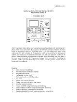
3. DECRIPTION OF CONTROLS
The following section details the function and meaning of the various controls on the module.
O
AUTO
o
F
o
CRPMPSI
88 88 88 88 88 88
AV
L3
BAR
L1 L2 L2 N L1N L3 N
Hz
A
V
V
Deep Sea Electronics plc
Model 560
Scroll Button
Auto Mode
Manual Mode
Stop/Reset
Common Alarm Indicator
User Configurable LCD
Indications with text insert pocket
LCD Display
Selector Switch
FIG2
3.1 TYPICAL LCD DISPLAY SCREENS
INSTRUMENTS
4
1
7. 3 40
9
.
6
3
9
9
.
7
L1-L2 L2-L3 L3-L1
V
(phase to phase AC volts)
The LCD displays the various engine parameters such as ‘ENGINE
SPEED’
, ‘OIL PRESSURE’, ‘HOURS RUN’, etc.
Each instrument is displayed with the appropriate units of measure.
ALARM ICONS
PSI
0.0 0.0
BAR
The LCD also displays the exact nature of any alarm condition
which have occurred such as
LOW OIL PRESSURE using
appropriate icons. This allows very specific alarm conditions to be
brought to the operators’ attention. Refer to the ‘Protections’
section of this manual for details of the alarms.
USER DEFINED
INDICATIONS
The LCD displays the user defined indications when configured and
active. The icons will illuminate and point to the appropriate text
insert label. These indications can be used to indicate the
operation of external equipment (i.e. ‘Battery Charger On’, ‘Breaker
Closed’ etc) or to indicate internal states (i.e. Engine Running,
Safety On, etc).
USER DEFINED ALARMS
!
!
The LCD displays the user defined alarms when configured and
active. The icons will illuminate and point to the appropriate text
insert label. These alarms can be used to indicate the operation of
external alarms (i.e. ‘Low Fuel Level’, ‘Low Coolant level’ etc) or to
indicate internal alarms (i.e. Fail to Stop, MPU fault, etc).

DSE Model 560 Automatic Start Engine Management and Instrumentation System Operators Manual
560 OPERATING MANUAL ISSUE 5 4/4/02 MR
16
LCD DISPLAY AREAS
NOTE:- The Engine Hours Run counter will only display the accumulated hours to the
nearest 12 Minutes Hour (0.2Hr). The accumulated time will be recorded in HH:MM
however. [Pre V1.4 Modules recorded hours run to the nearest ½ Hour (0.5)]
CAUTION!:-If the DC supply to the module is interrupted the hours run counter will not
remember any ‘un-displayed’ minutes accumulated since the last 12 Minute display update.
i.e.
10 Hours 38 Minutes accumulated before DC supply is removed…
(10.6 Hours displayed)
would become …10 Hours 36Minutes on restoration of DC supply.
(10.6 Hours still displayed)
This will only occur in the event of a total DC supply break and will NOT occur if the module
is simply switched to the Stop/Reset position.
Instrument Values
Units of Measure
Display Information &
A
larm Icons
User Definable Alarms/Indicators

DSE Model 560 Automatic Start Engine Management and Instrumentation System Operators Manual
560 OPERATING MANUAL ISSUE 5 4/4/02 MR 17
VIEWING THE INSTRUMENTS
It is possible to manually scroll to display the different instruments by repeatedly operating the scroll
button, once selected the instrument will remain on the LCD display until the user selects a
different instrument or after a period of inactivity the module will revert to the initial display.
Instrument Page Order:-
• Frequency / RPM
• AC Voltage Line-Neutral (<<<Not Shown on 3 phase 3 wire (Delta) version of the module)
• AC Voltage Line-Line
•
AC Line Current
•
Oil Pressure
•
Coolant temperature
•
Engine Hours Run
•
DC Battery Voltage
Manually Selecting an Instrument
Initial display
>>>>>>>
>
Hz
RPM
51.0
1530
Pressing the DOWN button the LCD will
then show…
2
1
2
.
3
2
0
9
.
1
1
9
6
.
7
L1-N L2-N L3-N
V
Pressing the DOWN button again the
LCD will then show…
…. Etc
417.3 409.6 3
99
.
7
L1- L2 L2- L3 L3- L1
V
Pressing the button again will scroll through each individual instrument eventually returning
to the original instrument displayed.
NOTE:-Once selected the instrument will remain on the LCD display until the user
selects a different instrument or after a period of inactivity the module will revert to the
initial display.

DSE Model 560 Automatic Start Engine Management and Instrumentation System Operators Manual
560 OPERATING MANUAL ISSUE 5 4/4/02 MR
18
3.2 INDICATORS
COMMON ALARM LED
This LED indicates when an alarm condition is present.
The Alarms Page on the LCD will detail the exact nature
of the alarm.
• ‘OFF’ - no alarm active.
• ‘STEADY AMBER’ - A warning alarm is present.
• ‘FLASHING RED’ - A shutdown alarm is present.
• ‘STEADY RED’ - An Electrical trip alarm is present.
USER CONFIGURABLE LCD INDICATIORS
These LCD’s can be configured by the user to indicate
any on of the different functions based around the
following:-
• INDICATIONS - Monitoring of a digital input and
indicating associated functioning user’s equipment -
Such as Battery Charger On or Louver’s Open, etc.
• WARNINGS and SHUTDOWNS - Specific indication
of a particular warning or shutdown condition, backed
up by LCD indication (!)-
Such as Low Oil Pressure
Shutdown, Low Coolant level, etc.
•
STATUS INDICATIONS - Indication of specific
functions or sequences derived from the modules
operating state -
Such as Safety On, Pre-heating,
Generator Available, etc.
3.3 CONTROLS
STOP/RESET
This position places the module into it’s Stop/reset mode. This will clear
any alarm conditions for which the triggering criteria have been removed.
If the engine is running and this position is selected, the module will
automatically instruct the change-over device to un-load the generator
(‘Load transfer’ becomes in-active (if used)). The fuel supply will be
removed and engine will be brought to a standstill. Should a
remote start
signal
be present while operating in this mode, a remote start will not
occur.
AUTO
This position places the module into it’s ‘Automatic’ mode. This mode
allows the module to control the function of the generator automatically.
The module will monitor the
remote start input and once a start condition
is signalled the set will be automatically started and placed on load
(‘Load
transfer’ becomes active (if used))
. If the starting signal is removed the
module will automatically transfer the load from the generator and shut the
set down observing the stop delay timer and cooling timer as
necessary. The module will then await the next start event.
For further
details please see the more detailed description of ‘Auto Operation’ earlier
in this manual.
MANUAL
This position is used to allow manual control of the generator functions.
Once in
Manual mode the module will start the engine and run off load. If
the engine is running off-load in the
Manual mode and a remote start
signal
becomes present, the module will automatically instruct the
change-over device to place the generator on load
(‘Load transfer’
becomes active (if used))
. Should the remote start signal then be
removed the generator will remain on load until either the
‘STOP/RESET’
or ‘AUTO’ positions is selected.

DSE Model 560 Automatic Start Engine Management and Instrumentation System Operators Manual
560 OPERATING MANUAL ISSUE 5 4/4/02 MR 19
4. INSTALLATION INSTRUCTIONS
The model DSE 560 Module has been designed for front panel mounting. Fixing is by 4 spring
loaded clips for easy assembly.
4.1 PANEL CUT-OUT
138.00mm
185.00mm
FIG 3
In conditions of excessive vibration the module should be mounted on suitable anti-vibration
mountings.
4.2 COOLING
The module has been designed to operate over a wide temperature range -30 to +70º C. However
allowances should be made for the temperature rise within the control panel enclosure. Care
should be taken NOT to mount possible heat sources near the module unless adequate ventilation
is provided. The relative humidity inside the control panel enclosure should not exceed 95%.
4.3 UNIT DIMENSIONS
All dimensions in mm.
144.0mm
137mm
184.0mm
110.0mm
7.5mm
Panel Cut-out:138mmx185mm
192.0mm
:
CE
FIG 4

DSE Model 560 Automatic Start Engine Management and Instrumentation System Operators Manual
560 OPERATING MANUAL ISSUE 5 4/4/02 MR
20
4.4 FRONT PANEL LAYOUT
O
AUTO
o
F
o
CRPMPSI
88 88 88 88 88 88
AV
L3
BAR
L1 L2 L2 N L1N L3 N
Hz
A
V
V
Deep Sea Electronics plc
Model 560
FIG 5
4.5 REAR PANEL LAYOUT
:
CE
FIG 6
/