Page is loading ...

HGM400E Series Genset Controller
(HGM410E/HGM420E)
USER MANUAL
Smartgen Technology

Version
Date
Version
Note
2013-08-17
1.0
Original release.
2013-08-28
1.1
Change “Auxiliary Input” to “Emergency Shutdown”
This manual is suitable for HGM400E series controller only.
Clarification of notation used within this publication.
SYMBOL
INSTRUCTION
NOTE
Highlights an essential element of a procedure to ensure
correctness.
CAUTION!
Indicates a procedure or practice, which, if not strictly observed,
could result in damage or destruction of equipment.
WARNING!
Indicates a procedure or practice, which could result in injury to
personnel or loss of life if not followed correctly.

HGM400E Series Automatic Control Module
HGM400E Series Genset Controller ISSUE 2013-08-28 Version 1.1 Page 4 of 41
CONTENTS
1 OVERVIEW....................................................................................... 5
2 PERFORMANCE AND CHARACTERISTICS ................................... 6
3 SPECIFICATION ............................................................................... 8
4 OPERATION ..................................................................................... 9
4.1 PUSHBUTTONS .............................................................................................. 9
4.2 INDICATOR LIGHT ........................................................................................ 10
4.3 AUTOMATIC START/STOP OPERATION ..................................................... 11
4.4 MANUAL START/STOP OPERATION ........................................................... 12
5 PROTECTION ................................................................................ 13
5.1 WARNINGS ................................................................................................... 13
5.2 SHUTDOWN ALARM .................................................................................... 15
6 CONNECTIONS ............................................................................. 18
7 DEFINITION AND RANGE OF PARAMETERS ............................... 21
7.1 PARAMETER CONTENTS AND RANGE (TABLE 1) ..................................... 21
7.2 PROGRAMMABLE OUTPUT 1-5 (TABLE 2) ................................................. 29
7.3 PROGRAMMABLE INPUT 1-4 TABLE (ACTIVE WHEN CONNECT GND (B-)
(TABLE 3) .............................................................................................................. 30
7.4 SENSOR SELECT (TABLE 4) ....................................................................... 31
7.5 CONDITIONS OF CRANK DISCONNECT (TABLE 5) ................................... 32
8 PARAMETERS SETTING ............................................................... 33
9 SENSOR SELECT .......................................................................... 35
10 COMMISSIONING .......................................................................... 36
11 TYPICAL APPLICATION ................................................................. 37
12 INSTALLATION ............................................................................... 39
12.1 FIXING CLIPS ............................................................................................... 39
12.2 OVERALL DIMENSION AND PANEL CUTOUT ............................................. 39
13 FAULT FINDING ............................................................................. 41

HGM400E Series Automatic Control Module
HGM400E Series Genset Controller ISSUE 2013-08-28 Version 1.1 Page 5 of 41
1 OVERVIEW
HGM400E series genset controllers integrate digitization, intelligentization and
network technology which are used for genset automation and monitor control system
of single unit to achieve automatic start/stop, data measure, alarm protection and
“three remote” (remote control, remote measuring and remote communication; SG485
module must be fitted). It fit with LCD display, optional languages interface (Chinese,
English, Spanish and Russian), and it is reliable and easy to use.
HGM400E series genset controllers adopt micro-processor technology with precision
parameters measuring, fixed value adjustment, time setting and set value adjusting
and etc. All parameters can be configured from front panel or through programmable
interface (USB to LINK, can use SG72 adaptor) via PC. It can be widely used in all
types of automatic genset control system with compact structure, advanced circuits,
simple connections and high reliability.

HGM400E Series Automatic Control Module
HGM400E Series Genset Controller ISSUE 2013-08-28 Version 1.1 Page 6 of 41
2 PERFORMANCE AND CHARACTERISTICS
HGM400E series controller has two types:
HGM410E: ASM (Automatic Start Module),it controls generator to start/stop by
remote signal;
HGM420E: AMF (Auto Mains Failure), updates based on HGM410E, moreover, has
mains electric quantity monitoring and mains/generator automatic transfer control
function, especially for automatic system composed by generator and mains.
132x64 LCD with backlight, selectable language interface (Chinese, English,
Spanish and Russian), push-button operation;
Suitable for 3-phase 4-wire, 3-phase 3-wire, single phase 2-wire, and 2-phase
3-wire systems with voltage 120/240V and frequency 50/60Hz;
Collects and shows 3-phase voltage, current, power parameter and frequency of
generator or mains.
Mains Generator
Line Voltage (Uab, Ubc, Uca) Line Voltage (Uab, Ubc, Uca)
Phase Voltage (Ua, Ub, Uc) Phase Voltage (Ua, Ub, Uc)
Frequency (HZ) Frequency (HZ)
Load
Current (IA, IB, IC)
Active Power (KW)
Reactive Power (KVar)
Apparent Power (KVA)
Power Factor (PF)
Accumulated Energy (kWh)
For Mains, controller has over voltage, under voltage and loss of phase detection
functions; For generator, controller has over voltage, under voltage, over frequency,
under frequency and over current detection functions;
Precision measure and display parameters about Engine,
Temp. (WT) °C/°F both be displayed
Oil pressure (OP) kPa/Psi/Bar all be displayed
Fuel Level % (Unit)
Engine Speed (RP) RPM (Unit)

HGM400E Series Automatic Control Module
HGM400E Series Genset Controller ISSUE 2013-08-28 Version 1.1 Page 7 of 41
Battery Voltage (VB) V (unit)
Charger Voltage (VD) V (unit)
Hours counter (HC): Max. 999999 hours
Start times: Max.999999 times
Protection: automatic start/stop of the genset, ATS(Auto Transfer Switch) control
with perfect fault indication and protection function;
With ETS, idle control, pre-heat control, speed raise control and speed drop control,
All output ports are relay-out;
Parameter setting: parameters can be modified and cannot be lost even in case of
power outage; all the parameters can be adjusted using front panel of the controller
or via PC using an SG72 adaptor.
Multiplex input port 3 and 4 can be used in various fields: input 3 can be used as
digital input port or fuel level sensor while input 4 can be used as digital input port
or flexible sensor.
More kinds of curves of temperature, oil pressure, fuel level can be used directly
and users can define the sensor curves by themselves;
Flexible sensor: can be set as temperature sensor, oil pressure sensor or fuel level
sensor, enable the detection of double temperature, double oil-pressure and
double fuel level.
Multiple crank disconnect conditions (speed sensor, oil pressure, generator
frequency) are optional;
Widely Power supply range: DC(8~35)V, suitable to different start battery voltage
environment.
All parameters used digital adjustment, instead of conventional analog modulation
with normal potentiometer, more reliability and stability;
Modular design, anti-flaming ABS plastic enclosure, pluggable connection terminals
and embedded installation way; compact structure with easy mounting.

HGM400E Series Automatic Control Module
HGM400E Series Genset Controller ISSUE 2013-08-28 Version 1.1 Page 8 of 41
3 SPECIFICATION
Items Contents
Working Voltage DC8. 0V to 35. 0V, Continuous Power Supply.
Overall Consumption <3W(Standby mode: ≤2W)
AC voltage Input:
3 Phase 4 Wire
2 Phase 3 Wire
Single phase 2 Wire
3 Phase 3 Wire
AC15V - AC360V (ph-N)
AC15V - AC360V (ph-N)
AC15V - AC360V (ph-N)
AC30V - AC620V (ph-ph)
Alternator Frequency 50Hz/60 Hz
Speed Sensor Voltage 1.0V to 24V (effective value)
Speed Sensor Frequency 10,000 Hz (max)
Start Relay Output 5A DC28V power supply
Programmable Relay Output 1 5A DC28V power supply
Programmable Relay Output 2 5A DC28V power supply
Programmable Relay Output 3 5A DC28V power supply
Programmable Relay Output 4 5A AC250V voltage-free output
Programmable Relay Output 5 5A AC250V voltage-free output
Overall Dimensions 130mm x 112mm x 39mm
Panel Cutout 110mm x 90mm
CT Secondary Current 5A (rated)
Working Condition Temperature: (-25~70)ºC;
Humidity: (20~93)%RH
Storage Condition Temperature: (-25~70)ºC
Protection Level IP55 Gasket
Insulation Intensity
Apply AC2.2kV voltage between high voltage
terminal and low voltage terminal;
The leakage current is not more than 3mA within
1min.
Weight 0.26kg

HGM400E Series Automatic Control Module
HGM400E Series Genset Controller ISSUE 2013-08-28 Version 1.1 Page 9 of 41
4 OPERATION
4.1 PUSHBUTTONS
Stop/ Reset
Stop running generator in Auto/Manual mode;
In case of alarm condition, pressing the button will reset
alarm;
In stop mode, pressing and holding the button for 3
seconds will test indicator lights (lamp test);
During stopping process, press this button again to stop
generator immediately.
Start Start genset in Manual/Test mode.
Manual Pressing this key will set the module into manual mode.
Pressing and (or ) simultaneously can
adjust LCD contrast.
Automatic Pressing this key will set the module into auto mode.
Set/Confirm Pressing this key will enter into Main Menu;
In setting parameter status, press this key will shift cursor
or confirm setting value.
Up/Increase Scrolls the screen up;
Shift the cursor up or increase the set value in
parameter setting menu.
Down/Decrease Scrolls the screen down;
Shift the cursor down or decrease the set value in
parameter setting menu.

HGM400E Series Automatic Control Module
HGM400E Series Genset Controller ISSUE 2013-08-28 Version 1.1 Page 10 of 41
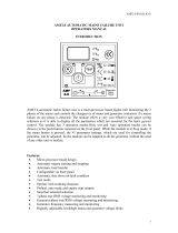
4.2 INDICATOR LIGHT
HGM410E Panel Indicators
HGM420E Panel Indicators

HGM400E Series Automatic Control Module
HGM400E Series Genset Controller ISSUE 2013-08-28 Version 1.1 Page 11 of 41
4.3 AUTOMATIC START/STOP OPERATION
Auto mode is selected by pressing the button; a LED besides the button will
illuminate to confirm the operation.
Auto Start Sequence,
1) HGM420E: when mains is abnormal (over/under voltage, loss of phase), enter into
“Mains Abnormal Delay” and LCD displays count down time. When the delay is over,
“Start Delay” timer is initiated.
2) HGM410E: When “Remote Start” is active, “Start Delay” timer is initiated;.
3) “Start Delay” countdown will be displayed on LCD;
4) When start delay is over, preheat relay energizes (if configured), “preheat delay XXs”
information will be displayed on LCD;
5) After the above delay, the Fuel Relay is energized, and then one second later, the
Start Relay is engaged. The engine is cranked for a pre-set time. If the engine fails to
fire during this cranking attempt then the fuel relay and start relay are disengaged for
the pre-set rest period; “crank rest time” begins and wait for the next crank attempt.
6) Should this start sequence continue beyond the set number of attempts, the start
sequence will be terminated, the first line of LCD display will be highlighted with
black and Fail to Start fault will be displayed.
7) In case of successful crank attempt, the “Safety On” timer is activated, allowing Low
Oil Pressure, High Temperature, Under speed, Charge Alternator Failure and Aux.
inputs (configured) to stabilise without triggering the fault. As soon as this delay is
over, “start idle” delay is initiated (if configured).
8) During “start idle” delay, under speed, under frequency, under voltage alarms are
inhibited. When this delay is over, “warming up” delay is initiated (if configured).
9) After the “warming up” delay, if generator status is normal, its indicator will be
illuminated. If generator voltage and frequency have reached on-load requirements,
then the generator close relay will be energized; genset will take load; generator
power indicator will illuminate and generator will enter into Normal Running status. if
voltage or frequency is abnormal, the controller will initiate shutdown alarm (alarm
information will be displayed on LCD).
Auto Stop Sequence,
1) HGM420E: during normal running process, if mains normal, enters into “Mains
Normal Delay”. When mains indicator illuminates, “Stop Delay” begins.
2) HGM410E: When the “Remote Start” signal is removed, the Stop Delay is initiated.

HGM400E Series Automatic Control Module
HGM400E Series Genset Controller ISSUE 2013-08-28 Version 1.1 Page 12 of 41
3) Once this “stop delay” has expired, the Generator Breaker will open and the “Cooling
Delay” is then initiated. After “Transfer Delay”, the mains close relay will be
energized; mains will take load; generator power indicator will extinguish while mains
power indicator will illuminate.
4) During “Stop Idle” Delay (if configured), idle relay is energized.
5) “ETS Solenoid Hold” begins, ETS relay is energized while fuel relay is de-energized.
6) "Fail to Stop Delay" begins, complete stop is detected automatically.
7) Generator is placed into its standby mode after its complete stop. Otherwise, fail to
stop alarm is initiated and the corresponding alarm information is displayed on LCD.
4.4 MANUAL START/STOP OPERATION
1) HGM420E: Manual mode is selected by pressing the button; a LED besides the
button will illuminate to confirm the operation; Press key, select “Mode Select”,
then choose “Test Mode”. Under the two modes, press button to start the genset,
it can automatically judge crank success and accelerate to high speed running. If high
temperature, low oil pressure, over speed and abnormal voltage occur during genset
running, controller can effectively protect genset to stop (detail procedures please
refer to No.4~9 of Auto start sequence). Under Manual Mode , if mains normal,
load breaker won’t transfer; if mains abnormal, load breaker will transfer to generator.
Under Test Mode, after genset high speed normal running, no matter mains normal
or not, load will be transferred to generator.
2) HGM410E: Manual mode is selected by pressing the button; a LED besides the
button will illuminate to confirm the operation; Then press button to start the
generator, it can automatically judge crank success and accelerate to high speed
running. If high temperature, low oil pressure, over speed and abnormal voltage
occur during genset running, controller can effectively protect genset to stop (detail
procedures please refer to No.4~9 of Auto start sequence). After genset high speed
normal running, controller will send Gen Closed signal.
3) Manual stop: pressing key can shut down the running genset. (detail procedures
please refer to No.3~7 of Auto stop sequence)

HGM400E Series Automatic Control Module
HGM400E Series Genset Controller ISSUE 2013-08-28 Version 1.1 Page 13 of 41
5 PROTECTION
5.1 WARNINGS
When controller detects the warning signal, only alarm and not lead to shutdown. The
alarm information will be displayed on LCD.
Warnings types are as follows,
No. Items Description
1 High
Temperature
When the controller detects that engine temperature has
exceeded the pre-set value while shutdown is prohibited, or
detects that the Aux. input high temperature while shutdown
is prohibited, it will initiate a warning alarm and the
corresponding alarm information will be displayed on LCD.
2 Low Oil
Pressure
When the controller detects that the oil pressure has fallen
below the pre-set value while shutdown is prohibited, or
detects that the Aux. input low oil pressure while shutdown is
prohibited, it will initiate a warning alarm and the
corresponding alarm information will be displayed on LCD.
3 Gen Over
Current
When the controller detects that the genset current has
exceeded the pre-set value and the over current delay has
expired, it will initiate a warning alarm and the corresponding
alarm information will be displayed on LCD.
4 Fail To Stop
After “fail to stop” delay/ ETS delay, if gen-set does not stop
completely, it will initiate a warning alarm and the
corresponding alarm information will be displayed on LCD.
5 Low Fuel Level
When the controller detects that the fuel level has fallen
below the pre-set value while shutdown is prohibited, or
detects that the Aux. input low fuel level while shutdown is
prohibited, it will initiate a warning alarm and the
corresponding alarm information will be displayed on LCD.
6 Charge Alt
Failure
When the controller detects that charger voltage has fallen
below the pre-set value, it will initiate a warning alarm and
the corresponding alarm information will be displayed on
LCD.
7 Battery Under
Volt
When the controller detects that battery voltage has fallen
below the pre-set value, it will initiate a warning alarm and
the corresponding alarm information will be displayed on
LCD.
8 Battery Over
Volt
When the controller detects that battery voltage has
exceeded the pre-set value, it will initiate a warning alarm
and the corresponding alarm information will be displayed on
LCD.

HGM400E Series Automatic Control Module
HGM400E Series Genset Controller ISSUE 2013-08-28 Version 1.1 Page 14 of 41
9 Auxiliary Input When the controller detects that the auxiliary input warning
signals, it will initiate a warning alarm and the corresponding
alarm information will be displayed on LCD.
10 Loss Of Speed
Signal
When the controller detects that the engine speed is 0 and
the delay is 0, it will initiate a warning alarm and the
corresponding alarm information will be displayed on LCD.
11 Low Coolant
Level
When the controller detects the low coolant level input is
active, it will initiate a warning alarm and the corresponding
alarm information will be displayed on LCD.
12 Temp. Sensor
Open
When the controller detects that the temperature sensor is
open circuit and the action select “Warn”, it will initiate a
warning alarm and the corresponding alarm information will
be displayed on LCD.
13 Oil Pressure
Sensor Open
When the controller detects that the oil pressure sensor is
open circuit and the action select “Warn”, it will initiate a
warning alarm and the corresponding alarm information will
be displayed on LCD.
14 Level Sensor
Open
When the controller detects that the level sensor is open
circuit and the action select “Warn”, it will initiate a warning
alarm and the corresponding alarm information will be
displayed on LCD.
15 Temp. Sensor
2 Open
If the flexible sensor set as temperature sensor, When the
controller detects that the temperature sensor is open circuit
and the action select “Warn”, it will initiate a warning alarm
and the corresponding alarm information will be displayed on
LCD.
16 Oil Pressure
Sensor 2
Open
If the flexible sensor set as oil pressure sensor, When the
controller detects that the oil pressure sensor is open circuit
and the action select “Warn”, it will initiate a warning alarm
and the corresponding alarm information will be displayed on
LCD.
17
Level Sensor 2
Open
If the flexible sensor set as level sensor, When the controller
detects that the level sensor is open circuit and the action
select “Warn”, it will initiate a warning alarm and the
corresponding alarm information will be displayed on LCD.
18 High
Temperature 2
When the controller detects that flexible sensor temperature
(sensor type: temperature sensor) has exceeded the pre-set
value while shutdown is prohibited, it will initiate a warning
alarm and the corresponding alarm information will be
displayed on LCD.

HGM400E Series Automatic Control Module
HGM400E Series Genset Controller ISSUE 2013-08-28 Version 1.1 Page 15 of 41
19 Low Oil
Pressure 2
When the controller detects that flexible sensor oil pressure
(sensor type: oil pressure sensor) has fallen below the
pre-set value while shutdown is prohibited, it will initiate a
warning alarm and the corresponding alarm information will
be displayed on LCD.
20 Low Fuel Level
2
When the controller detects that flexible sensor fuel level
(sensor type: level sensor) has fallen below the pre-set value
while shutdown is prohibited, it will initiate a warning alarm
and the corresponding alarm information will be displayed on
LCD.
5.2 SHUTDOWN ALARM
When controller detects shutdown alarm, it will send signal to open breaker and stop the
genset. The alarm information will be displayed on LCD.
No Items Description
1 Emergency
Shutdown
When the controller detects that the emergency shutdown
signal, it will initiate a shutdown alarm and the corresponding
alarm information will be displayed on LCD.
2 High
Temperature
When controller detects that the water/cylinder temperature
has exceeded the pre-set value, it will initiate a shutdown
alarm and the corresponding alarm information will be
displayed on LCD.
3 Low Oil
Pressure
When the controller detects that the oil pressure has fallen
below the pre-set value, it will initiate a shutdown alarm and
the corresponding alarm information will be displayed on
LCD.
4 Over Speed
When the controller detects that the generator speed has
exceeded the pre-set value, it will initiate a shutdown alarm
and the corresponding alarm information will be displayed on
LCD.
5 Under Speed
When the controller detects that the generator speed has
fallen below the pre-set value, it will initiate a shutdown alarm
and the corresponding alarm information will be displayed on
LCD.
6 Loss Of Speed
Signal
When the controller detects that the engine speed is 0 and
the delay is NOT 0, it will initiate a shutdown alarm and the
corresponding alarm information will be displayed on LCD.
7 Gen Over
Voltage
When the controller detects that the genset voltage has
exceeded the pre-set value, it will initiate a shutdown alarm
and the corresponding alarm information will be displayed on
LCD.
8 Gen
Under
Voltage
When the controller detects that the genset voltage has
fallen below the pre-set value, it will initiate a shutdown alarm
and the corresponding alarm information will be displayed on

HGM400E Series Automatic Control Module
HGM400E Series Genset Controller ISSUE 2013-08-28 Version 1.1 Page 16 of 41
No Items Description
LCD.
9 Gen Over
Current
When the controller detects that the genset current has
exceeded the pre-set value and delay is not 0, it will initiate a
shutdown alarm and the corresponding alarm information will
be displayed on LCD.
10 Fail To Start If the engine does not fire after the pre-set number of
attempts, it will initiate a shutdown alarm and the
corresponding alarm information will be displayed on LCD.
11 Gen Over
Frequency
When the controller detects that the genset frequency has
exceeded the pre-set value, it will initiate a shutdown alarm
and the corresponding alarm information will be displayed on
LCD.
12 Gen Under
Frequency
When the controller detects that the genset frequency has
fallen below the pre-set value, it will initiate a shutdown alarm
and the corresponding alarm information will be displayed on
LCD.
13 Genset Failed When the controller detects that the genset frequency is 0, it
will initiate a shutdown alarm and the corresponding alarm
information will be displayed on LCD.
14 Low Fuel Level
When the controller detects that the fuel level has fallen
below the pre-set value or detects that the low fuel level input
is active, it will initiate a shutdown alarm and the
corresponding alarm information will be displayed on LCD.
15 Low Coolant
Level
When the controller detects the low coolant level input is
active, it will initiate a shutdown alarm and the corresponding
alarm information will be displayed on LCD.
16 Temp. Sensor
Open
When the controller detects that the temperature sensor is
open circuit and the action select “Shutdown”, it will initiate a
shutdown alarm and the corresponding alarm information will
be displayed on LCD.
17 Oil Pressure
Sensor Open
When the controller detects that the oil pressure sensor is
open circuit and the action select “Shutdown”, it will initiate a
shutdown alarm and the corresponding alarm information will
be displayed on LCD.
18 Level Sensor
Open
When the controller detects that the level sensor is open
circuit and the action select “Shutdown”, it will initiate a
shutdown alarm and the corresponding alarm information will
be displayed on LCD.
19 Temp. Sensor 2
Open
If the flexible sensor set as temperature sensor, When the
controller detects that the temperature sensor is open circuit
and the action select “Shutdown”, it will initiate a shutdown
alarm and the corresponding alarm information will be
displayed on LCD.

HGM400E Series Automatic Control Module
HGM400E Series Genset Controller ISSUE 2013-08-28 Version 1.1 Page 17 of 41
No Items Description
20 Oil Pressure
Sensor 2 Open
If the flexible sensor set as oil pressure sensor, When the
controller detects that the oil pressure sensor is open circuit
and the action select “Shutdown”, it will initiate a shutdown
alarm and the corresponding alarm information will be
displayed on LCD.
21
Level Sensor 2
Open
If the flexible sensor set as level sensor, When the controller
detects that the level sensor is open circuit and the action
select “Shutdown”, it will initiate a shutdown alarm and the
corresponding alarm information will be displayed on LCD.
22 High
Temperature 2
When the controller detects that flexible sensor temperature
(sensor type: temperature sensor) has exceeded the pre-set
value, it will initiate a shutdown alarm and the corresponding
alarm information will be displayed on LCD.
23 Low Oil
Pressure 2
When the controller detects that flexible sensor oil pressure
(sensor type: oil pressure sensor) has fallen below the
pre-set value, it will initiate a shutdown alarm and the
corresponding alarm information will be displayed on LCD.
24 Low Fuel Level
2
When the controller detects that flexible sensor fuel level
(sensor type: level sensor) has fallen below the pre-set
value, it will initiate a shutdown alarm and the corresponding
alarm information will be displayed on LCD.

HGM400E Series Automatic Control Module
HGM400E Series Genset Controller ISSUE 2013-08-28 Version 1.1 Page 18 of 41
6 CONNECTIONS
Compared with HGM420E, HGM410E has no Mains AC Voltage input terminals. The
rear panel of HGM410E and HGM420E is as below.
Description of terminal connections:
Pin Function Cable
Size Description
1 B- 1.5mm2 DC power supply. Connected with
negative of starter battery.
2 B+ 1.5mm2
DC power supply. Connected with
positive of starter battery. If wire length is
over 30m, better to double wires in
parallel. Max. 20A fuse is recommended.
3 Aux. Output 1 1.0mm2 B+ is supplied by 2 point, rated 5A.
4 Crank 1.0mm2 B+ is supplied by 2 point, rated 5A.
Connect to starter coil.
5 Aux. Output 2 1.0mm2 B+ is supplied by 2 point, rated 5A.
6 Aux. Output 3 1.0mm2 B+ is supplied by 2 point, rated 5A.
7 Aux. Input 1 1.0mm2 Ground connected is
active (B-)
See Table 3 8 Aux. Input 2 1.0mm2Ground connected is
active (B-)
9 Aux. Input 3 1.0mm2 Ground connected is
active (B-); Can be used

HGM400E Series Automatic Control Module
HGM400E Series Genset Controller ISSUE 2013-08-28 Version 1.1 Page 19 of 41
Pin Function Cable
Size Description
as Level Sensor.
10 Aux. Input 4 1.0mm2 Ground connected is
active (B-); Can be used
as Flexible Sensor.
11 Engine Temperature
Sensor 1.0mm2 Connect to a
temperature/cylinder
resistance sensor. See Table 4
12 Oil Press Sensor 1.0mm2 Connect to a oil pressure
resistance sensor.
13 CT A Phase Sensing 1.5mm2 Outside connected to secondary coil of
current transformer(rated 5A)
14 CT B Phase Sensing 1.5mm2 Outside connected to secondary coil of
current transformer(rated 5A)
15 CT C Phase Sensing 1.5mm2 Outside connected to secondary coil of
current transformer(rated 5A)
16 CT COM 1.5mm2 See INSTALLATION in the manual.
17 Magnetic Pickup 0.5mm2
Connect to speed sensor;
Shielded wire is recommended.
The other end of speed sensor connects
to B-.
18 Charger D+ 1.0mm2 Connect to charging starter’s D+
terminal. If there is no this terminal, then
be hang up.
19 Aux. Output 4 1.0mm2 The combination of terminal 19 and 21 is
relay normally open contact; rated 5A;
Voltage free.
20 Aux. Output 5 1.0mm2 The combination of terminal 20 and 21 is
relay normally open contact; rated 5A;
Voltage free.
21 Aux. Output COM 1.5mm2 Common terminal of auxiliary output 4
and 5.
22 Gen U Phase Sensing 1.0mm2 Connected to U-phase of generator (2A
fuse is recommended)
23 Gen V Phase Sensing 1.0mm2 Connected to V-phase of generator (2A
fuse is recommended)
24 Gen W Phase Sensing 1.0mm2 Connected to W-phase of generator (2A
fuse is recommended)
25 Gen N2 Input 1.0mm2 Connected to N-wire of generator.
26 Mains R Phase Voltage
Sensing 1.0mm2 Connected to R-phase of mains (2A fuse
is recommended) (HGM410E without)
27 Mains S Phase Voltage 1.0mm2 Connected to S-phase of mains (2A fuse

HGM400E Series Automatic Control Module
HGM400E Series Genset Controller ISSUE 2013-08-28 Version 1.1 Page 20 of 41
Pin Function Cable
Size Description
Sensing is recommended) (HGM410E without)
28 Mains T Phase Voltage
Sensing 1.0mm2 Connected to T-phase of mains (2A fuse
is recommended) (HGM410E without)
29 Mains N1 Sensing 1.0mm2 Connected to N-wire of mains
(HGM410E without)
NOTE: LINK interface is parameters programmable interface that can be
programmed by PC using an SG72 adapter. If there is need to remote control the
genset, please use the SG485 module produced by our company.

HGM400E Series Automatic Control Module
HGM400E Series Genset Controller ISSUE 2013-08-28 Version 1.1 Page 21 of 41
7 DEFINITION AND RANGE OF PARAMETERS
7.1 PARAMETER CONTENTS AND RANGE (TABLE 1)
No Items Range Default Description
1 Mains Normal
Delay (0-3600)s 10 The time from mains abnormal to
normal or from normal to
abnormal; suitable for ATS
(automatic transfer switch).
2 Mains Abnormal
Delay (0-3600)s 5
3 Mains Under
Voltage (30-620)V 184
When mains voltage has fallen
below the set value, Mains Under
Voltage is active. When set the
value as 30V, the controller does
not detect under voltage signal.
Back lash: 10V
4 Mains Over
Voltage (30-620)V 276
When mains voltage has exceed
the set value, Mains Over
Voltage is active. When set the
value as 620V, the controller
does not detect over voltage
signal. Back lash: 10V
5 Transfer Time (0-99.9)s 1.0
Interval time from mains switch
off to generator switch on; or
from generator switch off to
mains switch on.
6 Start Delay (0-3600)s 1 Time from mains abnormal or
remote start signal is active to
start genset.
7 Stop Delay (0-3600)s 1 Time from mains normal or
remote start signal is deactivated
to genset stop.
8 Start Attempts (1-10)times 3
Maximum crank times of crank
attempts. When reach this
number, controller will send start
failure signal.
9 Preheat Delay (0-300)s 0 Power-on time of heater plug
before starter is powered up.
10 Cranking Time (3-60)s 8 Power-on time of starter
11 Crank Rest Time (3-60)s 10 The waiting time before second
power up when engine start fail.
/