Page is loading ...

057-042 704 Operating Instructions Issue 2.1 18/06/2007 11:27:00 JR - 1 -
COMPLEX SOLUTIONS
MADE SIMPLE
DEEP SEA ELECTRONICS PLC
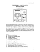
DSE704
AUTOSTART CONTROL MODULE
OPERATING MANUAL
http://bestgenerator.spb.ru/?page_id=6765

- 2 - 057-042 704 Operating Instructions Issue 2.1 18/06/2007 11:27:00 JR
Deep Sea Electronics Plc
Highfield House
Hunmanby
North Yorkshire
YO14 0PH
ENGLAND
Sales Tel: +44 (0) 1723 890099
Sales Fax: +44 (0) 1723 893303
E-mail: [email protected]
Website: www.deepseaplc.com
DSE Model 704 Control System Operators Manual
© Deep Sea Electronics Plc
All rights reserved. No part of this publication may be reproduced in any material form (including photocopying
or storing in any medium by electronic means or other) without the written permission of the copyright holder
except in accordance with the provisions of the Copyright, Designs and Patents Act 1988.
Applications for the copyright holder’s written permission to reproduce any part of this publication should be
addressed to Deep Sea Electronics Plc at the address above.
Any reference to trademarked product names used within this publication is owned by their respective
companies.
Deep Sea Electronics Plc reserves the right to change the contents of this document without prior
notice.

057-042 704 Operating Instructions Issue 2.1 18/06/2007 11:27:00 JR - 3 -
TABLE OF CONTENTS
1 DESCRIPTION OF OPERATION .......................................................... 4
1.1 MANUAL MODE OPERATION ......................................................................... 4
1.2 AUTOMATIC MODE OF OPERATION ............................................................. 5
1.3 WARNINGS ....................................................................................................... 6
1.4 SHUTDOWNS ................................................................................................... 6
2 CONFIGURATION INSTRUCTIONS ..................................................... 7
3 CONFIGURATION TABLES ................................................................. 8
4 TERMINAL DESCRIPTION ................................................................. 12
5 SPECIFICATION ................................................................................. 13
6 SOLID STATE OUTPUTS ................................................................... 14
7 DIMENSIONS ...................................................................................... 15
8 TYPICAL CONNECTIONS .................................................................. 15

- 4 - 057-042 704 Operating Instructions Issue 2.1 18/06/2007 11:27:00 JR
1 DESCRIPTION OF OPERATION
1.1 MANUAL MODE OPERATION
To initiate a start sequence in MANUAL, press the pushbutton, and the start sequence is
initiated.
NOTE:- There is no Start Delay in this mode of operation.
If the pre-heat output option is selected this timer is then initiated, and the auxiliary output selected
is energised.
After the above delay the Fuel Solenoid is energised, then the Starter Motor is engaged.
The engine is cranked for a 10 second period. If the engine fails to fire during this cranking attempt
then the starter motor is disengaged for a 10 second period. Should this sequence continue
beyond the 3 starting attempts, the start sequence will be terminated and Fail to Start
fault
will be illuminated.
When the engine fires, the starter motor is disengaged and locked out at 20 Hz measured from the
Alternator output. Rising oil pressure can also be used to disconnect the starter motor, however it
cannot be used for underspeed or overspeed detection.
After the starter motor has disengaged, the Safety On timer is activated (which is fixed at 12
seconds), allowing Oil Pressure, High Engine Temperature, Under-speed, Charge Fail and any
delayed Auxiliary fault inputs to stabilise without triggering the fault.
Once the engine is running, the Warm Up timer, if selected, is initiated, allowing the engine to
stabilise before it can be loaded.
The generator will run off load, unless the mains supply fails or a Remote Start on load signal is
applied, at which point the load will be transferred to the generator.
The generator will continue to run On load regardless of the state of the mains supply or remote
start input until the Auto mode is selected.
If Auto mode is selected, and the mains supply is healthy with the remote start on load signal not
active, then the Remote Stop Delay Timer begins, after which, the load is disconnected. The
generator will then run off load allowing the engine a cooling down period.
Selecting STOP
de-energises the FUEL SOLENOID, bringing the generator to a stop.
NOTE:- The safety on time (used for delayed alarms) is pre set to 12 seconds and can
not be changed.

057-042 704 Operating Instructions Issue 2.1 18/06/2007 11:27:00 JR - 5 -
1.2 AUTOMATIC MODE OF OPERATION
This mode is activated by pressing the pushbutton. An LED indicator beside the button
confirms this action.
Whether the start sequence is initiated by mains (utility) failure or by remote start input, the
following sequence is followed:
To allow for short term mains supply transient conditions or false remote start signals, the Start
Delay timer is initiated. After this delay, if the pre-heat output option is selected then the pre-heat
timer is initiated, and the corresponding auxiliary output (if configured) will energise.
NOTE:- If the mains supply returns within limits, (or the Remote Start signal is
removed if the start sequence was initiated by remote start) during the Start Delay timer,
the unit will return to a stand-by state.
After the above delays the Fuel Solenoid is energised, then one second later, the Starter Motor is
engaged.
The engine is cranked for a 10 second period. If the engine fails to fire during this cranking attempt
then the starter motor is disengaged for a 10 second rest period. Should this sequence continue
beyond the 3 starting attempts, the start sequence will be terminated and
Fail to Start
fault will be illuminated.
When the engine fires, the starter motor is disengaged and locked out at 20 Hz measured from the
Alternator output. Rising oil pressure can also be used to disconnect the starter motor, however it
cannot be used for underspeed or overspeed detection.
After the starter motor has disengaged, the Safety On timer is activated, allowing Oil Pressure,
High Engine Temperature, Under-speed, Charge Fail and any delayed Auxiliary fault inputs to
stabilise without triggering the fault.
Once the engine is running, the Warm Up timer, if selected is initiated, allowing the engine to
stabilise before accepting the load.
If the remote start is being used and has been configured to Remote start is on load, or the mains
has failed, the load will be transferred to the generator.
On the return of the mains supply, (or removal of the Remote Start signal if the set was started by
remote signal), the Stop delay timer is initiated. Once it has timed out, the load is transferred back
to the mains (utility). The Cooling timer is then initiated, allowing the engine a cooling down period
off load before shutting down. Once the Cooling timer expires the Fuel Solenoid is de-energised,
bringing the generator to a stop.
If the mains should fail (or a Remote Start signal is re-activated) whilst the generator is Cooling
down, the load will be immediately transferred to the generator.
Should the mains supply fall outside limits again (or the Remote Start signal be re-activated)
during the cooling down period, the set will return on load.
NOTE:- The safety on time (used for delayed alarms) is pre set to 12 seconds and can
not be changed.

- 6 - 057-042 704 Operating Instructions Issue 2.1 18/06/2007 11:27:00 JR
1.3 WARNINGS
Warnings are used to warn the operator of an impending fault
BATTERY CHARGE FAILURE, if the module does not detect a voltage from the warning light
terminal on the auxiliary charge alternator, the
icon will illuminate. (Either 8 Volts or 16 Volts
depending on the configuration of Nominal DC Voltage).
Inputs 1 and 2 can be configured as warnings or shutdowns. The relevant icon will be illuminated
when the input is active
1.4 SHUTDOWNS
Shutdowns are latching and stop the Generator. The alarm must be cleared, and the fault removed
to reset the module. In the event of a shutdown the appropriate icon will be illuminated
NOTE:- The alarm condition must be rectified before a reset will take place. If the
alarm condition remains it will not be possible to reset the unit (The exception to this is the
Low Oil Pressure alarm and similar ‘delayed alarms’, as the oil pressure will be low with
the engine at rest). Any subsequent warnings or shutdowns that occur will be displayed
steady, therefore only the first-up shutdown will appear flashing.
NOTE:- The safety on time (used for delayed alarms) is pre set to 12 seconds and can
not be changed.
FAIL TO START, if the engine does not fire after the pre-set 3 attempts at starting, a shutdown will
be initiated.
The
icon will illuminate.
LOW OIL PRESSURE, if the module detects that the engine oil pressure has fallen below the low
oil pressure switch after the Safety On timer has expired, a shutdown will occur.
The
icon will illuminate.
HIGH ENGINE TEMPERATURE if the module detects that the engine coolant temperature has
exceeded the high engine temperature switch after the Safety On timer has expired, a shutdown
will occur.
The
icon will illuminate.
OVERSPEED, if the engine speed exceeds the pre-set trip (14% above the nominal frequency) a
shutdown is initiated. Overspeed is not delayed, it is an immediate shutdown.
The icon will illuminate.
NOTE:- During the start-up sequence the overspeed trip level is extended to 24%
above the normal frequency for the duration of the saftey timer to allow an extra trip level
margin. This is used to prevent nuisance tripping on start-up.
UNDERSPEED, if the engine speed falls below the pre-set trip (20% of the nominal frequency)
after the Safety On timer has expired, a shutdown is initiated.
The
icon will illuminate.
Inputs 1 and 2 can be configured as warnings or shutdowns. The relevant icon will be illuminated
when the input is active

057-042 704 Operating Instructions Issue 2.1 18/06/2007 11:27:00 JR - 7 -
2 CONFIGURATION INSTRUCTIONS
♦ With the unit in Stop mode, Configuration Mode is selected by operation of a small
switch on the rear, left-hand edge of the PCB. This is partially hidden to prevent accidental
operation.
♦ Once Configuration Mode is selected, the ‘Auto’ LED will commence rapid flashing, and all
normal operation is suspended.
♦ The Stop
pushbutton can be used to select the LED ‘code’ that corresponds to the
required function. The 5 left-hand LED’s will form the code. See configuration table over leaf.
♦ The Manual
pushbutton will allow the user to change the associated value. The 3 right-
hand LED’s inform the user of the current setting for the chosen function. See configuration
table over leaf.
♦ When the required parameters are displayed, pressing the Auto
button will save
the new setting, and the process is repeated for each function change.
♦ When configuration is complete, the Configuration Mode Selector Switch should be returned
to the ‘Normal’ position.
Parameter Value
Normal
Configuration

- 8 - 057-042 704 Operating Instructions Issue 2.1 18/06/2007 11:27:00 JR
3 CONFIGURATION TABLES
FUNCTIONS AND CONFIGURATION TABLE
Function
! 1 ! 2
Value (Default in Bold)
Pre-heat Timer
{ { { {
O
{ { {
0 Seconds
{ {
O
5 Seconds
{
O
{
10 Seconds
{
O O
15 Seconds
O
{ {
20 Seconds
O
{
O
30 Seconds
O O
{
60 Seconds
O O O
180 Seconds
Used to pre-heat the engine prior to cranking. The output is active for the duration of the setting, prior to cranking.
Start Delay
{ { {
O
{
{ { {
0 Seconds
{ {
O
5 Seconds
{
O
{
10 Seconds
{
O O
15 Seconds
O
{ {
20 Seconds
O
{
O
30 Seconds
O O
{
60 Seconds
O O O
180 Seconds
Used to give a delay between activating the remote start input, or a mains failure, and actually starting the engine.
Stop Delay
Mains Return Delay
{ { {
O O
{ { {
0 Seconds
{ {
O
5 Seconds
{
O
{
10 Seconds
{
O O
15 Seconds
O
{ {
20 Seconds
O
{
O
30 Seconds
O O
{
60 Seconds
O O O
180 Seconds
Used to give a delay between the mains returning and the system switching the load back to the mains. Used to ensure
that the mains is steady before this action is executed.
Energise to Stop
Hold Timer
{ {
O
{ {
{ { {
0 Seconds
{ {
O
5 Seconds
{
O
{
10 Seconds
{
O O
15 Seconds
O
{ {
20 Seconds
O
{
O
30 Seconds
O O
{
60 Seconds
O O O
180 Seconds
Used for the control of the engine stop solenoid. When the engine is to be stopped, the Energise To Stop output
becomes active, closing the stop solenoid (fuel valve). When the engine comes to rest, the stop solenoid will remain
energised for the period of the Energise To Stop Timer, to ensure the engine has come to a complete stop.
Warm-up Timer
{ {
O
{
O
{ { {
0 Seconds
{ {
O
5 Seconds
{
O
{
10 Seconds
{
O O
15 Seconds
O
{ {
20 Seconds
O
{
O
30 Seconds
O O
{
60 Seconds
O O O
180 Seconds
Delay between the engine being available for use, and the closure of the generator load-switching device to allow time
for the engine to warm before being loaded. This occurs after the 12 second safety on timer.
Cooling Timer
{ {
O O
{
{ { {
0 Seconds
{ {
O
5 Seconds
{
O
{
10 Seconds
{
O O
15 Seconds
O
{ {
20 Seconds
O
{
O
30 Seconds
O O
{
60 Seconds
O O O
180 Seconds
Delay between opening the generator load-switching device and stopping the engine to allow time for the engine to
cool down before being stopped. This is particularly useful when used in conjunction with turbo-charged engines.

057-042 704 Operating Instructions Issue 2.1 18/06/2007 11:27:00 JR - 9 -
FUNCTIONS AND CONFIGURATION TABLE
Function
! 1 ! 2
Value (Default in Bold)
Nominal Frequency
{
O
{ { {
{ { {
50 Hz (O/S +14% /
Overshoot +24%)
{ {
O
60 Hz (O/S +14% /
Overshoot +24%)
The systems nominal frequency. Either 50 Hz or 60 Hz
Nominal DC Voltage
{
O
{ {
O
{ { {
12V DC (CF 8V)
{ {
O
24V DC (CF 16V)
The generator battery voltage. Either 12 Volts or 24 Volts. It is used for the charge alternator failure level.
LOP Switch Contact
{
O
{
O
{
{ { {
Close on Fault
{ {
O
Open on Fault
Configuration for the oil pressure switch. Either to close to battery negative on a fault, or open on a fault.
HET Switch Contact
{
O
{
O O
{ { {
Close on Fault
{ {
O
Open on Fault
Configuration for the coolant temperature switch. Either to close to battery negative on a fault, or open on a fault.
Crank disconnect on
Oil Pressure
{
O O
{ {
{ { {
Disabled
{ {
O
Enabled (2 Second
Delay)
If this is enabled, the starter motor will disconnect 2 seconds after the oil pressure switch detects oil pressure.
NOTE:- Not suitable for all generators, due to the different monitoring points on lubrication systems.
Underspeed
Detection
{
O O
{
O
{ { {
Disabled
{ {
O
Enabled (U/S –20%)
If this is enabled, the unit will shut down the generator if the frequency falls below 20% of the nominal frequency.
Remote start
function
{
O O O
{
{ { {
Remote start
{ {
O
Simulated mains
Programmable input can be configured to one of the following.
♦ Remote start – If the input is active the generator will be started, and stopped if the input is deactive. Mains fail is
allways active.
♦ Simulated mains – If the input is active the generator will not start in the event of a mains failure. E.G. if the
generator is supporting a non 24 hour operation, a 24 hour timer can be used to prevent a mains failure from
starting the generator and taking load.
Remote start on load
(ignore if simulated
mains)
{
O O O O
{ { {
Remote start is off
load
{ {
O
Remote start is on load
The remote start input can be configured to one of the following.
♦ Remote start is off load – The generator will start and run off load when the remote start input is active.
♦ Remote start is on load – The generator will start, and the load transferred to the generator when the remote start
is active.

- 10 - 057-042 704 Operating Instructions Issue 2.1 18/06/2007 11:27:00 JR
FUNCTIONS AND CONFIGURATION TABLE
Function
! 1 ! 2
Value (Default in Bold)
Auxiliary Input 1
Function
O
{ { { {
{ { {
Immediate Warning
Close on Fault
{ {
O
Immediate Warning
Open on Fault
{
O
{
Immediate Shutdown
Close on Fault
{
O O
Immediate Shutdown
Open on Fault
O
{ {
Delayed Warning
Close on Fault
O
{
O
Delayed Warning
Open on Fault
O O
{
Delayed Shutdown
Close on Fault
O O O
Delayed Shutdown
Open on Fault
Programmable input, can be configured to on of the following
♦ Immediate warning close on fault – If the input is activated at any time the unit will alarm and energise the
common warning and common alarm output.
♦ Immediate warning open on fault – If the input is deactivated at any time the unit will alarm and energise the
common warning and common alarm output.
♦ Immediate shutdown close on fault – If the input is activated at any time the generator will be shutdown and
energise the common warning and common shutdown output. The generator can not be started.
♦ Immediate shutdown open on fault – If the input is deactivated at any time the generator will be shutdown and
energise the common warning and common shutdown output. The generator can not be started.
♦ Delayed warning close on fault – If the input is activated and the saftey time has elapsed the unit will alarm and
energise the common warning and common alarm output.
♦ Delayed warning open on fault – If the input is deactivated and the saftey time has elapsed the unit will alarm and
energise the common warning and common alarm output.
♦ Delayed shutdown close on fault – If the input is activated and the saftey time has elapsed the generator will be
shutdown and energise the common warning and common shutdown output.
♦ Delayed shutdown open on fault – If the input is deactivated and the saftey time has elapsed the generator will be
shutdown and energise the common warning and common shutdown output.
Auxiliary Input 2
Function
O
{ { {
O
{ { {
Immediate Warning
Close on Fault
{ {
O
Immediate Warning
Open on Fault
{
O
{
Immediate Shutdown
Close on Fault
{
O O
Immediate Shutdown
Open on Fault
O
{ {
Delayed Warning
Close on Fault
O
{
O
Delayed Warning
Open on Fault
O O
{
Delayed Shutdown
Close on Fault
O O O
Delayed Shutdown
Open on Fault
Programmable input, can be configured to on of the following
♦ Immediate warning close on fault – If the input is activated at any time the unit will alarm and energise the
common warning and common alarm output.
♦ Immediate warning open on fault – If the input is deactivated at any time the unit will alarm and energise the
common warning and common alarm output.
♦ Immediate shutdown close on fault – If the input is activated at any time the generator will be shutdown and
energise the common warning and common shutdown output. The generator can not be started.
♦ Immediate shutdown open on fault – If the input is deactivated at any time the generator will be shutdown and
energise the common warning and common shutdown output. The generator can not be started.
♦ Delayed warning close on fault – If the input is activated and the saftey time has elapsed the unit will alarm and
energise the common warning and common alarm output.
♦ Delayed warning open on fault – If the input is deactivated and the saftey time has elapsed the unit will alarm and
energise the common warning and common alarm output.
♦ Delayed shutdown close on fault – If the input is activated and the saftey time has elapsed the generator will be
shutdown and energise the common warning and common shutdown output.
♦ Delayed shutdown open on fault – If the input is deactivated and the saftey time has elapsed the generator will be
shutdown and energise the common warning and common shutdown output.

057-042 704 Operating Instructions Issue 2.1 18/06/2007 11:27:00 JR - 11 -
FUNCTIONS AND CONFIGURATION TABLE
Function
! 1 ! 2
Value (Default in Bold)
Auxiliary Output 1
Function
O
{ {
O
{
{ { {
Not used
{ {
O
Pre-heat
{
O
{
Engine Running
{
O O
Common Warning
O
{ {
Common Shutdown
O
{
O
System in Auto
O O
{
Common Alarm
O O O
Energise to Stop
Programmable output can be configured to one of the following.
♦ Pre-heat. - The output is energised for the period of pre-heat time prior to cranking, and between the cranking
attempts.
♦ Engine Running. - The output is active after the saftey timer has elapsed.
♦ Common warning. - The output is active if there are any warning alarm active.
♦ Common shutdown - The output is active if there are any shutdown alarms active.
♦ System in auto. - The output is active when the system is in automatic mode.
♦ Common Alarm. - The output is active if there is any alarm condition.
♦ Energise to stop. - The output is energised when the engine is required to stop (normal or fault conditions), and
will remain energised for the period of the Energise To Stop Timer, to ensure the engine has come to a complete
stop.
Auxiliary Output 2
Function
O
{ {
O O
{ { {
Not used
{ {
O
Pre-heat
{
O
{
Engine Running
{
O O
Common Warning
O
{ {
Common Shutdown
O
{
O
System in Auto
O O
{
Common Alarm
O O O
Energise to Stop
Programmable output can be configured to one of the following.
♦ Pre-heat. - The output is energised for the period of pre-heat time prior to cranking, and between the cranking
attempts.
♦ Engine Running. - The output is active after the saftey timer has elapsed.
♦ Common warning. - The output is active if there are any warning alarm active.
♦ Common shutdown - The output is active if there are any shutdown alarms active.
♦ System in auto. - The output is active when the system is in automatic mode.
♦ Common Alarm. - The output is active if there is any alarm condition.
♦ Energise to stop. - The output is energised when the engine is required to stop (normal or fault conditions), and
will remain energised for the period of the Energise To Stop Timer, to ensure the engine has come to a complete
stop.
Mains Under
Voltage
(Trip / Return)
O
{
O
{ {
{ { {
60V / 70V
{ {
O
70V / 80V
{
O
{
80V / 90V
{
O O
90V / 100V
O
{ {
120V / 140V
O
{
O
140V / 160V
O O
{
160V / 180V
O O O
180V /200V
If for example 180/200 is selected the generator will be started and the load transferred if any phase falls below 180V
with respect to the neutral for the duration of the delay start timer. The load will be transferred back to mains when the
mains voltage returns to 200V or higher for the duration of the mains return timer. (The system must be in Auto)

- 12 - 057-042 704 Operating Instructions Issue 2.1 18/06/2007 11:27:00 JR
4 TERMINAL DESCRIPTION
PIN
No
DESCRIPTION CABLE
SIZE
NOTES
1
DC Plant Supply Input
(-ve)
1.0mm
Connected to plant battery negative
2
DC Plant Supply Input
(+ve)
1.0mm
Connected to plant battery positive
(Recommended Fuse 2A)
3
Fuel relay Output
1.0mm
Used to operate the fuel relay.
4
Start relay Output
1.0mm
Used to operate the cranking relay.
5
Auxiliary Output relay 1
1.0mm
Configurable output.
6
Auxiliary Output relay 2
1.0mm
Configurable output.
7
Charge Fail Input/ Excitation
Output
1.0mm
Must NOT be connected to plant supply
negative if not used.
8
Low Oil Pressure Input
0.5mm
Switch to negative.
9
High Engine Temp Input
0.5mm
Switch to negative.
10
Auxiliary Input 1
0.5mm
Switch to negative.
11
Auxiliary Input 2
0.5mm
Switch to negative.
12
Remote Start Input
0.5mm
Switch to negative.
13
Mains loading Relay
Normally Open contact
1.0mm
Used to close the mains
contactor / breaker
14
Generator loading Relay
Normally Open contact
1.0mm
Used to close the generator
contactor / breaker
15
Functional Earth
1.0mm
Connect to a good clean earth point
16
Mains L1
Voltage Monitoring Input
1.0mm
Connect to Mains L1 supply (AC)
(Recommend 2A Fuse Max.)
17
Mains L2
Voltage Monitoring Input
1.0mm
Connect to Mains L1 supply (AC)
(Recommend 2A Fuse Max.)
18
Mains L3
Voltage Monitoring Input
1.0mm
Connect to Mains L1 supply (AC)
(Recommend 2A Fuse Max.)
19
Mains N
Voltage Monitoring Input
1.0mm
Connect to Mains N supply (AC)
20
Alternator Input L1
1.0mm
Do not connect if not used. (2A Fuse)
21
Alternator Input N
1.0mm
Do not connect if not used.
NOTE:- For single phase mains monitoring the neutral should be connected to terminal
19, L1 should be connected to terminals 16,17 and 18.
NOTE:- For two phase mains monitoring the L2 should be connected to terminal 19, L1
should be connected to terminals 16,17 and 18. The voltage between the two phases must
not exceed 305 Volts.
NOTE:- All the outputs are solid state, rated at 1.2 Amps 8 Volts to 35 Volts DC, and
switch to battery negative when active.

057-042 704 Operating Instructions Issue 2.1 18/06/2007 11:27:00 JR - 13 -
5 SPECIFICATION
DC Supply: 8 Volts to 35 Volts DC Continuous.
Cranking Dropouts: Able to survive 0 Volts for 50 mS, providing supply was at
least 10 V before dropout and supply recovers to 5 Volts.
This is achieved without the need for internal batteries.
Max. Current: Operating 50mA
Standby 10mA
Alternator Input Range: 75 Volts (ph-N) to 277 Volts (ph-N) AC (+20%)
Mains Input Voltage 15 – 277 Volts (ph-N) AC (+20%)
Alternator Input Frequency: 50 - 60 Hz at rated engine speed
(Minimum: 75V AC Ph-N)
(Crank Disconnect from 15V Ph-N @ 20Hz)
Overspeed +14% (+24% overshoot)
Underspeed –20%
Mains Frequency 50 – 60 Hz
Start Output: 1.2 Amp DC at supply voltage.
Fuel Output: 1.2 Amp DC at supply voltage.
Auxiliary Outputs: 1.2 Amp DC at supply voltage.
Dimensions: 125mm x 165mm x 28 mm
Charge Fail: 12 Volts = 8 Volts CF 24 Volts = 16 Volts CF
Operating Temperature Range:
-30°C to + 70
0
C
Applicable Standards
Compliant with BS EN 60950 Low Voltage Directive
Compliant with BS EN 50081-2: 1992 EMC Directive
Compliant with BS EN 61000-6-4: 2000 EMC Directive
Compliance to European Legislation
Registered Component for USA & Canada
Deep Sea Electronics plc reserve the right to change specification without notice.

- 14 - 057-042 704 Operating Instructions Issue 2.1 18/06/2007 11:27:00 JR
6 SOLID STATE OUTPUTS
DSE’s utilisation of Solid State Outputs gives many advantages, the main points being:
♦ No Moving Parts
♦ Fully Overload / Short Circuit Protected.
♦ Smaller dimensions hence lighter, thinner and cheaper than conventional relays.
♦ Less power required making them far more reliable.
The main difference from conventional outputs is that solid state outputs switch to negative (–ve)
when active. This type of output is normally used with an automotive or plug in relay.
TYPICAL CONNECTIONS
Battery positive (+)
S
olid state output
f
rom D
S
E module
eg. Terminal 3 of 703/4 - FUEL
Fuel Solenoid (+ terminal)
* Observe polarity when using
relays fitted with integral diodes!
*
A
D
B
C
A
B
C
D
Solid State Output
from DSE Module Pin
Automotive
relay Pin
8 Pin Plugin relay Function
3 86 7 Fuel Output
85 2 To Positive supply via fuse
30 1 To Positive supply via fuse
87 3 To Fuel Solenoid
Example of relay pins connected to DSE solid state output to drive a fuel solenoid.
See overleaf for overall typical wiring diagram
NOTE:- The Close Mains Relay should be NORMALLY CLOSED when de-energised for fail
safe reasons. Should the DC supply fail the mains will always be available. The output from the
DSE solid state output when energised will OPEN the relay therefore isolating the mains supply.

057-042 704 Operating Instructions Issue 2.1 18/06/2007 11:27:00 JR - 15 -
7 DIMENSIONS
Dimensions:
165mm x 125mm x 29mm
(6.5” x 4.9” x 1.2”)
Panel cutout:
149mm x 109mm
(5.9” x 4.3”)
Mounting Method:
4 x 4.2mm diameter holes suitable for M4
screws.
8 TYPICAL CONNECTIONS
F 2A
SSOSSOSSOSSO
SSO = Solid state outputs
= External 'Automotive' or 'Plug-in' type relays
4
1 2
3
5 6 7
2021
Auxiliary Outputs
+
+
8 9 10 11
12
Auxiliary Alarm
Inputs
+
Battery
F2A F
Crank
Fuel
Starter
motor
Charge
alt
+ +
Fuel output
Start output
N
L1
L2
L3
Alternator Output
Load
Mechanical Interlock
N
L1
L2
L3
Mains / Utility supply
14
SSO
Close Gen output
+
G
M
Electrical Interlock
13
SSO
Close mains output
FUSES 2A
Oil Pressure
Engine temperature
Remote Start
Normally closedNormally open
16 17 18 19
Close mains relayClose gen relay
+
*
NOTE
* Close mains relay must be normally closed
to ensure fail safe operation
15
Terminals suitable for 22-16 awg (0.6mm
2
-1.3mm
2
)field wiring
Tightening Torque = 0.8N-m (7lb-in)
http://bestgenerator.spb.ru/?page_id=6765
/