Page is loading ...

Neo-cool Circulator
Model
CF300/701/1100
Instruction Manual
- Fourth Edition -
Yamato Scientific Co. LTD.,
This paper has been printed on recycled paper.
z Thank you for purchasing " Neo-cool Circulator, CF
Series" of Yamato Scientific Co., Ltd.
z To use this unit properly, read this "Instruction
Manual" thoroughly before using this unit.
Keep this instruction manual around this unit for
referring at anytime.
WARNING!:
Carefully read and thoroughly understand the
important warning items described in this manual
before using this unit.

Contents
Cautions in Using with Safety................................................................1
•
Explanation.................................................................................................................... 1
•
Table of Illustrated Symbols .......................................................................................... 2
•
Fundamental Matters of “WARNING!” and “CAUTION!” ............................................... 3
•
Fundamental Matters of “WARNING!” and “CAUTION!” ............................................... 4
Before Using this unit.............................................................................5
• Requirements for Installation......................................................................................... 5
Description and Function of Each Part.................................................8
•
Main Unit and Control panel.......................................................................................... 8
Installation Method..................................................................................9
Operation Method .................................................................................11
•
Procedure of Operation............................................................................................... 11
Handling Precautions ...........................................................................12
Maintenance Method.............................................................................13
• Daily Inspection and Maintenance .............................................................................. 13
Long storage and disposal...................................................................14
•
When not using this unit for long term / When disposing ............................................ 14
In the Event of Failure….......................................................................15
After Service and Warranty ..................................................................16
Specification..........................................................................................17
Wiring Diagram......................................................................................18
Replacement Parts Table......................................................................21
Reference...............................................................................................22
•
List of Dangerous Substances .................................................................................... 22

1
Cautions in Using with Safety
Explanation
MEANING OF ILLUSTRATED SYMBOLS
Various symbols are used in this safety manual in order to use the unit without
danger of injury and damage of the unit. A list of problems caused by ignoring
the warnings and improper handling is divided as shown below.Be sure that you
understand the warnings and cautions in this manual before operating the unit.
WARNING!
If the warning is ignored, there is the danger of a problem that
may cause a serious accident or even fatality.
CAUTION!
If the caution is ignored, there is the danger of a problem that may
cause injury/damage to property or the unit itself.
Meaning of Symbols
This symbol indicates items that urge the warning (including the caution).
A detailed warning message is shown adjacent to the symbol.
This symbol indicates items that are strictly prohibited.
A detailed message is shown adjacent to the symbol with specific actions not to
perform.
This symbol indicates items that should be always performed.
A detailed message with instructions is shown adjacent to the symbol.
Illustrated Symbols

2
Cautions in Using with Safety
Table of Illustrated Symbols
Warning
Warning,
generally
Warning,
high voltage
Warning,
high temperature
Warning,
drive train
Warning,
explosive
Caution
Caution,
generally
Caution,
electrical shock
Caution,
scald
Caution,
no road heating
Caution,
not to drench
Caution,
water only
Caution,
deadly poison
Prohibit
Prohibit,
generally
Prohibit,
inflammable
Prohibit,
to disassemble
Prohibit,
to touch
Compulsion
Compulsion,
generally
Compulsion,
connect to the
grounding
terminal
Compulsion,
install on a flat
surface
Compulsion,
disconnect the
power plug
Compulsion,
periodical
inspection

3
Cautions in Using with Safety
Fundamental Matters of “WARNING!” and “CAUTION!”
WARNING!
Do not use this unit in an area where there is flammable or explosive gas
Never use this unit in an area where there is flammable or explosive gas.
This unit is not explosion-proof. An arc may be generated when the power switch is turned on or off,
and fire/explosion may result. (Refer to page22 “List of Dangerous Substances”.)
Always ground this unit
Always ground this unit on the power equipment side in order to avoid electrical shock due to a power
surge.
If a problem occurs
If smoke or strange odor should come out of this unit for some reason, turn off the power key right
away, and then turn off the circuit breaker and the main power. Immediately contact a service
technician for inspection. If this procedure is not followed, fire or electrical shock may result. Never
perform repair work yourself, since it is dangerous and not recommended.
Do not use the power cord if it is bundled or tangled
Do not use the power cord if it is bundled or tangled. If it is used in this manner, it can overheat and
fire may be caused.
Do not process, bend, wring, or stretch the power cord forcibly
Do not process, bend, wring, or stretch the power cord forcibly. Fire or electrical shock may result.
Pay special attention to the measure for flammability
and handling of flammable solvent
Leaving at the temperature higher than the room temperature may vaporize the flammable material
(ethanol, etc.). There might be the case that some flammable liquid might be vaporized at the
temperature lower than the room temperature. The result of such careless handling could cause the
fire or explosion. Do provide the vaporization with enough during the operation.
Do not disassemble or modify this unit
Do not disassemble or modify this unit. Fire or electrical shock or failure may be caused.

4
Cautions in Using with Safety
Fundamental Matters of “WARNING!” and “CAUTION!”
CAUTION!
During a thunder storm
During a thunderstorm, turn off the power key immediately, then turn off the circuit breaker and the main
power. If this procedure is not followed, fire or electrical shock may be caused.
Do not touch the liquid in the cooling coil and trap bath
Since the liquid in the cooling coil and trap bath is stayed with low temperature, never touch it so as to
preventing from getting frostbite on your hands.
Do not touch the cooling fin with bare hands
Do not touch the cooling fin with bare hands during maintenance, for the edge of the cooling fin is too
sharp to cut your hand.

5
Before Using this unit
Requirements for Installation
WARNING!
1. Always ground this unit
• Connect the power plug to a receptacle with grounding connectors.
• Do not forget to ground this unit, to protect you and the unit from electrical shock in case of
power surge. Choose a receptacle with grounding connectors as often as possible.
• Do not connect the grounding wire to a gas pipe, or by means of a lightning rod or telephone
line. A fire or electrical shock will occur.
• The CF1100 type uses a triple-phase 200V power source. Be sure to connect this model to
the specific power switchboard or receptacle for 200V.
丸端子2-5
黒(T)(定格端子へ)
白(S)(定格端子へ)
赤(R)(定格端子へ)
緑(アース)
2. Choose a proper place for installation
• Do not install this unit in a place where:
♦ Rough or dirty surface.
♦ Flammable gas or corrosive gas is generated.
♦ Ambient temperature bellow 5℃ or above 35°C.
♦ Ambient temperature fluctuates violently.
♦ There is direct sunlight.
♦ There is excessive humidity and dust.
♦ There is a constant vibration.
• Install this unit on a stable place with the space as shown below.
More than
20cm
More than
20cm
Front side
More than 40cm
Main
Unit
Ring Terminal 2-5
Green (Ground)
Red (R) (to the specific terminal)
White (S) (to the specific terminal)
Black
(
T
)
(
to the s
p
ecific terminal
)

6
Before Using this unit
Requirements for Installation
3. Do not use this unit in an area where there is flammable or explosive gas
• Never use this unit in an area where there is
flammable or explosive gas. This unit is not
explosion-proof. An arc may be generated
when the power switch is turned ON or OFF,
and fire/explosion may result.
• To know about flammable or explosive gas
refer to page22 “List of Dangerous
Substances”.
4. Do not modify 5. Do not topple or tilt this unit
• Modification of this unit is strictly
prohibited. This could cause a failure.
• Set this unit to the flattest place. This
unit incorporates the refrigerator. Do
not topple or tilt it.
y
a
m
a
t
o
冷
凍
機
Y
ポ
ン
プ
入
切
CAUTION!
6. Use specified receptacle for power source
• Choose a correct power distribution board or receptacle that meets the unit’s rated electric
capacity.
Electric capacity: CF300: 100V AC, 50/60Hz, 6A
CF701: 100V AC, 50/60Hz, 10A
CF1100: 200V AC (triple phase), 50/60Hz, 6A
NOTE)
Starburst connection with a branching receptacle or extended wiring with a cord reel lowers
electrical power voltage, which may cause the degradation of refrigeration capability.
冷凍機ポンプ
切
入
Y
冷凍機ポンプ
切
入
Y

7
Before Using this unit
Requirements for Installation
7. Before/after installing
• It may cause injure to a person if this unit falls down or moves by the earthquake and the
impact. etc..To prevent, take measures that the unit cannot fall down, and not install to busy
place.
• Though this unit has the air-cooled refrigerator, the device exhausts the heat. Do provide the
vaporization with enough so as not to raise the ambient temperature caused by the exhaust of
the heat, or install this unit with its air controlled completely. If the ambient temperature
becomes high, the operation efficiency becomes worse, and could cause the malfunction of
the device by high temperature and humidity.
8. Handling of power code
• Do not entangle the power cord. This will cause overheating and possibly a fire.
• Do not bend or twist the power cord, or apply excessive tension to it. This may cause a fire
and electrical shock.
• Do not lay the power cord under a desk or chair, and do not allow it to be pinched in order to
prevent it from being damaged and to avoid a fire or electrical shock.
• Keep the power cord away from any heating equipment such as a room heater. The cord's
insulation may melt and cause a fire or electrical shock.
• If the power cord becomes damaged (wiring exposed, breakage, etc.), immediately turn off the
power at the rear of this unit and shut off the main supply power. Then contact your nearest
dealer for replacement of the power cord. Leaving it may cause a fire or electrical shock.
• Connect the power plug to the receptacl which is supplied appropriate power and voltage.
9. Before/after installing
• Connect the circulation port of the main body
to the coolant device securely so as not to
leak cooling liquid.
• Closing the circulation path with the solenoid
valve or throttle valve might cause the
malfunction of the pump such as water
leakage.
• Please open the stop valve of a CF701
discharge and the return at the time of the
pump driving by all means.
• Pay attention to the over-throttle. Throttle
the path with the flow rate of the device kept
1.5 liter per min. or more.
• In case that there are solenoid valve on the
device to be performed the circulation
cooling, or in case that the flow rate of the
device is lower than the 1.5 liter per min., set
the bypass circuit between the main device
and peripheral devices.
CF300/701/ 1100
Device with built- in type solenoid valve
Return
Discharge
hose
Bypass Circuit
Connecting Port
Outer Dia.: 11 mm hose nipple (CF300.701)
Outer Dia.: 16 mm hose nipple (CF1100)
10. Apply the 40% ethanol solution as the cooling liquid (heating medium)
• Adjust the water solution with its alcoholic density be 40% (Vol%) or more so as not to freeze
the cooling liquid. Note that the non-frozen liquid and ethylene glycol solution specified in JIS
K2234 have large argillaceos and specific gravity. These characters cause the overload to
the pump, and reduce the efficiency of the thermal conductivity. Therefore, do not apply
these solutions as the cooling liquid. Besides, the cooling liquid including flon has large
specific gravity, and cause the overload to the pump, and finally cause the corrosion to the
cooling coil. Never to apply these cooling liquids.

8
Description and Function of Each Part
Main Unit and Control panel
電源スイッチ
(漏電ブレーカ)
温度調節器
電源コード
冷凍機スイッチ
温度調節器
ポンプスイッチ
切
入
ポンプ
冷凍機
SEL
通風口
水位計
(窓)
定格銘板
製造番号銘板
ドレン
(CF300)
オーバーフロー
オーバーフロー
ドレン
(CF700.1100)
戻り口
(CF300)
吐出口
吐出口
(CF700.1100)
戻り口
CAUTION) CF701 is with a stop valve
Part Name Function
Power switch (Earth Leakage Breaker):
This is the power switch Turns ON/OFF the main power.
Temperature controller:
Controls the temperature of cooling liquid in the bath.
(Range: -20 to 30℃)
Refrigerator switch:
Turns ON/OFF the refrigerator.
Pump switch:
Turns ON/OFF the circulation pump.
Production
p
late
S
p
ecification
p
late
Power switch
(Earth leakage breaker)
Control
p
anel
Tem
p
erature controlle
r
Ventilation port
Pum
p
switch
Refrigerator switch
PUMP REFRIGE
ON
OFF
Power code
Water level meter
(Window)
Return port (CF300)
Discharge port (CF300)
Discharge port (CF701/1100)
Return port (CF701/1100)
Drain (CF300)
Overflow (CF300)
Overflow (CF701/1100)
Drain (CF701/1100)

9
Installation Method
1. Unlock the stopper of the caster.
(Only for CF701/1100)
Pulling up the lever of the stopper for
caster releases the lock.
(Only the two casters in front of the unit
are attached the stopped.)
2. Move the device to the place to be
installed.
If there is a step on the floor, the too strong
impact is given to the caster, and could give
the damage. In that case, move the
device by lifting at the step.
3. When the installation place is determined,
pull down the lever of the stopped for
caster, and lock them.
4. Drain/Overflow Cap Check.
• (CF300)
Check that the drain port and the
overflow port are sealed with the cap.
• (CF701/1100)
Check that the drain valve is set at the
“CLOSE” position.
オーバーフロー
ドレン
(付属品ビニールホース挿入口)
バルブ
ドレン
キャップ
CF300
オーバーフロー
ドレン
CF700/1100
蓋を外した状態
開
運転時
排水時の位置
タケノコ口
閉
Caster (CF701/1100)
Rubber foot (CF300)
Stopper
Release lock
Lock
Open
Close
Cover opened status
Draining position
(Operating)
Drain
v
alve
Overflow
(Optional vinyl hose inserting port)
Volute Port
Drain
Drain
Overflo
w
Cap
CF701/1100

10
Installation Method
5. Power Plug Connection
• Check the earth leakage breaker, the refrigerator switch and the pump switch are turned "OFF", and
plug the power cord in the receptacle.
6. Insert the cooling liquid into the bath
• Remove the cover of the bath, and insert the 40% ethanol solution into the bath with its cooling coil
hidden. When supplying the liquid, remove the cap (CF300) of the overflow on the left side surface of
the bath without fail, and prepare the pan for the bath. (The CF701/1100 overflow has the volute
port.)
• With this status, turn on the pump switch, and circulate the liquid. At this time, check that the liquid is
circulated with no abnormal noise. There would be the case that the liquid is not circulated because
of the remained air in the bath. Turn on and off the pump switch for several times for evacuating the
remained air. After completing the evacuation of the remained air, the liquid might be circulated.
Even though the liquid is not circulated yet, turn off the power of the refrigerator and pump switch
immediately, check the status of the relevant devices referring to Page 15 "In the Event of Failure…".
(Keeping the operation of the device without circulating the liquid could cause the malfunction of the
circulation pump.)
• After stabilizing the liquid circulation, supply the liquid up to the position where the cooling coil is
hidden with the liquid. Note that the water gauge on the left side surface of the main device indicates
the water position in the bath. Check that the liquid is filled up to the appropriate position.
• After supplying the liquid, turn OFF the power.
• Cover the bath.
オーバーフロー
キャップ
エタノール
40%水溶液
受け皿
CF300
水位計
(窓)
CF700/1100
オーバーフロー
ドレン
水位計
(窓)
エタノール
40%水溶液
受け皿
タケノコ口
40% ethanol
solution
40% ethanol
solution
Water level meter
(Window)
Water level meter
(Window)
Overflow cap
Pan
Pan
Overflow
Volute Port
Drain
CF701/1100

11
Operation Method
Procedure of Operation
1. Turn "ON" the earth leakage breaker.
ON
2. Set the temperature.
Set the temperature to be applied with the ”SEL”
key. Pressing the “SEL” key lights on the SV
indicating lamp. Set the temperature with “▲,▼”
keys, and press the “SEL” key again after checking
the setting status of the temperature.
SEL
SV
C1
3. Turning on switch of the refrigerator.
After checking the C1 lamp of the temperature
controller (control output 1) is turned ON, turn on the
switch of the refrigerator.
The device starts operation by the actuation of the
time after passing about 3 minutes.
Note:
The lighting on and off status of the “C1” lamp of the
temperature controller indicates the performance status
of the output contacting point.
Since the actual control temperature is controlled by the
“ON” and “OFF” of the refrigerator, the time delay
between the “C1” lamp motion of the temperature
controller and “ON” “OFF” timing of the refrigerator
might be occurred. This time delay might be caused
by the pre-setting of the 3-minute delay circuit for
preventing from the refrigerator malfunction.
ポンプ
冷凍機
切
入
SEL
4. Turning on the pump switch.
Check that the hose is connected between the
circulation port of the main device and cooling
device, and that the circulation liquid is filled into the
water bath. Then turn on the pump switch.
Please open the stop valve of a CF701 discharge
and the return at the time of the pump driving by all
means.
ポンプ
冷凍機
切
入
SEL
5. End of the operation.
Turn off the pump, refrigerator switch, and main
power switch.
PUMP REFRIGE
ON
OFF
PUMP REFRIGE
ON
OFF

12
Handling Precautions
WARNING!
If a problem occurs
If smoke or strange odor should come out of this unit for some reason, turn off the power key
right away, and then turn off the breaker and the main power. Immediately contact a service
technician for inspection. If this procedure is not followed, fire or electrical shock may result.
Never perform repair work yourself, since it is dangerous and not recommended.
Measure for flammability and handling of flammable solvent
This unit is not designed as the explosion-proof construction. Pay special attention to the
handling of the sample to be handled with this unit on the consumption with the explosive
material, flammable material, and similar ones. The flammable material may be vaporized by
leaving it at the temperature higher than room temperature, and could cause the fire or
explosion. When handling such material, provide ventilation with enough before the operation.
(Refer to page22 “List of Dangerous Substances”.)
CAUTION!
Water bath capacity
The water bath capacities of the CF300/701/1100 type devices are approx. 3 liters, 14 liters, and
37 liters. If the liquid is supplied over these capacities, the leakage of the liquid might be
occurred.
Do not step on this unit
Do not step on this unit. It will cause injury if this unit fall down or break.
Do not put anything on this unit
Do not put anything on this unit. It will cause injury if fall.
During a thunder storm
During a thunderstorm, turn off the power key immediately, then turn off the circuit breaker and
the main power. If this procedure is not followed, fire or electrical shock may be caused.
Countermeasure for stop operation during night or long-term stop
In case of stopping operation during night or long-term, toggle the power switch to "OFF".
Circulation pump protection
• Never operate the circulation pump with no liquid. Failure to do so could cause the
malfunction of the pump.
• If any obstacles are included in the cooling liquid, this obstacle might be caused the breakage
of the pump.
• In case that the solenoid valve and throttle valve are attached to the circulation path, do not
leave the valve in closed or too much throttled statuses for preventing from the pump damage.
• Always keep the flow rate of the circulation liquid at least 1.5 liter per min.

13
Maintenance Method
Daily Inspection and Maintenance
WARNING!
• Disconnect the power cable from the power source when doing an inspection or maintenance
unless needed.
• Perform the daily inspection and maintenance after returning the temperature of this unit to the
normal one.
• Do not disassemble this unit.
• Do not touch the cooling fin with bare hands.
CAUTION!
• Use a well-drained soft cloth to wipe dirt on this
unit. Do not use benzene, thinner or cleanser for
wiping. Do not scrub this unit. Deformation,
deterioration or color change may result in.
Monthly maintenance
• Check the earth leakage breaker function.
1. Connect the power cord.
2. Turn the breaker on.
3. Push the red test switch by a ballpoint pen etc.
4. If there is no problem, the earth leakage breaker will be turned off.
Cleaning of cooling fin
• Clogging of the cooling fin could cause the deterioration of
the cooling performance, and also cause the malfunction of
the refrigerator. The clogged status differs depending on
the surrounding condition or operation time. Clean the
cooling fin periodically.
Loosen the mounting screws (4 screws) of the ventilation port
cover, remove the cover of the ventilation port, and remove the
dust attached to the surface of the cover using the vacuum
cleaner.
After cleaning the cooling fin, attach it in inverse procedure.
Take care not to crush the fin during cleaning.
For any questions, contact the dealer who you purchased this unit from, or the nearest sales
division in our company.

14
Long storage and disposal
When not using this unit for long term / When disposing
CAUTION!
When not using this unit for long term…
• Turn off the power and disconnect the power cord.
WARNING!
When disposing…
• Keep out of reach of children.
• Treat as large trash.
Environmental protection should be considered
We request you to disassemble this unit as possible and recycle the reusable parts considering to
the environmental protection. The feature components of this unit and materials used are
listed below.
Component Name Material
Parts of Main Unit
Casing Bonderizing steel plate baked with melamine resin coating
Inner bath Stainless steel
Cover Stainless steel, Resin
Production plates Polyester (PET) resin film
Corner Alkylbenzenesulfied (ABS) resin
Caster (CF701/1100) Iron, Steel
Rubber foot (CF300) Synthetic rubber
Electrical Parts
Switches, Relays Composites with resin and others
Power cord & wiring
materials and others
Composites with synthetic rubber, copper, nickel and others
Fan motor Aluminum, Other synthetic
Pump Composites with iron, copper, resin, ceramic and others
Parts of Refrigeration System
Compressor Composites with iron, copper and others
Condenser Iron, Copper, Aluminum
Cooling device Nickel plated copper
Piping parts Composites with copper and others
Parts of Water Path
Drain, overflow and inner piping Silicon rubber
Connecting parts Resin
Insulating hose Polyurethane sponge
Sealed Cooling Medium for Refrigerator
Cooling medium R404A Ask the specialist for the dealing of cooling medium.

15
In the Event of Failure…
Trouble Shooting
Condition Possible Causes
Refrigerator does not start when
turning on the power switch.
• Power plug is not connected to the receptacle correctly.
• Power failure.
• Earth leakage breaker is turned to “OFF”
Not fallen the temperature.
• The cooling fin is clogged.
• The cooling liquid is overheated.
• The ambient temperature is exceeding 30℃or 35℃.
• The peripheral of the ventilating port is shut down.
Refrigerator cannot be restarted.
• The refrigerator is in overloaded. Turn off the power of the
refrigerator immediately, keep the temperature, and turn on
the power of the refrigerator after a while.
The liquid is not circulated.
• Is the circulation path is closed or throttled too narrow at any
point?
• Is the argillaceous or specific gravity of the cooling liquid
appropriate?
Error Display
Error Sign Cause Remedy
UUUU Sensor disconnection Check the sensor connection.
FALR
Malfunction of the
temperature controller
Stop operation. Turn off the power immediately,
In the case if the error other than listed above occurred, turn off the power switch and primary
power source immediately. Contact the shop of your purchase or nearest Yamato Scientific
Service Office.

16
After Service and Warranty
In Case of Request for Repair
If the failure occurs, stop the operation, turn OFF the power switch, and unplug the power plug.
Please contact the sales agency that this unit was purchased, or the Yamato Scientific's sales
office.
< Check following items before contact >
◆ Model Name of Product
◆ Production Number
◆ Purchase Date
◆ About Trouble (in detail as possible)
Minimum Retention Period of Performance Parts for Repair
The minimum retention period of performance parts for repair of this unit is 7 years after
discontinuance of this unit.
The "performance part for repair" is the part that is required to maintain this unit.
See the production plate attached to this unit.

17
Specification
Model CF300 CF701 CF1100
Circulation system Closed circulation
Operational
ambient temperature
5 to 35℃
Temperature setting range -20 to room temp -10 to room temp
385kcal・450W・at10℃ 770kcal・900W・at10℃ 2500kcal・2900W・at20℃
300kcal・350W・at0℃ 600kcal・700W・at0℃ 2100kcal・2440W・at10℃
Refrigerator
(AC100V 50Hz)
(kcal/h・W・liquid temp)
220kcal・260W・at-10℃ 410kcal・480W・at-10℃ -
Max.
flow
rate
50Hz: Approx. 14L/min
60Hz: Approx. 15.5L/min
(discharge pressure: 0kpa)
50Hz: Approx. 22L/min
60Hz: Approx. 22L/min
(discharge pressure: 0kpa)
50Hz: Approx. 40L/min
60Hz: Approx. 43L/min
(discharge pressure: 0kpa)
Max.
discharge
pressure
50Hz: Approx. 41kpa
60Hz: Approx. 55kpa
(flow rate: 0L/min)
50Hz: Approx. 98kpa
60Hz: Approx. 132kpa
(flow rate: 0L/min)
50Hz: Approx. 140kpa
60Hz: Approx. 199kpa
(flow rate: 0L/min)
Performance
Pump (*)
Rising range 4.2m/5.6m 10m/13.5m 14.3m/20.3m
Temperature
control system
Refrigerator ON/OFF
Temperature sensor T thermo couple (with SUS protection tube)
Temperature setting
/display system
Digital setting/display
Refrigerator Air cooling, 350W Air cooling, 600W Air cooling, 1100W
Cooling medium R404a
Cooling coil Nickel plated copper Copper
External circulation nozzle
Outer diameter: 11mm (both discharge and return)
with hose nipple
Outer diameter: 16mm
(RC1/2)
(both discharge and return)
with hose nipple
Circulation pump Magnetic pump 10/15W Magnetic pump 65/65W Magnetic pump 180/216W
Material SUS304
Bath
Dimensions φ174×170mm φ300×235mm φ370×400mm
Configuration
Capacity
Approx. 4L
(liquid quantity: 3L)
Approx. 16L
(liquid quantity: 14L)
Approx. 43L
(liquid quantity: 37L)
Safety devices
Electric leakage breaker, Overload relay keeping circuit for refrigerator,
Pump thermal protector, Delay timer for refrigerator protection
Overflow, Drainage, Water level meter
Other functions
- Aspirator unit attachable
Reverse phase
protection relay
External dimensions
(W×D×H mm)
210×400×500 350×480×840 420×650×1200
Weight Approx. 27Kg Approx. 54Kg Approx. 95Kg
Standards
Power supply 100V AC, 50/60Hz, 4.5A 100V AC, 50/60Hz, 10A
200V AC, 50/60Hz,
triple phase, 6A
Instruction manual, Circulation hose (1.5m)×2, Wire clamp ×2
Accessories
Cover Cover, Vinyl hose Vinyl hose
* At room temperature: 23℃, heat medium: water.

18
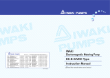
Wiring Diagram
CF300
AC100V
ELB 15A
S1 S2
8
9
5
4
TC
T1
TC1
1413
T1
12 8
X1
P
G
X1
FM1
FM2
X2
C1
C2
X2
3
2
2
1
1
1
3
OLR
C
6
5
4
6
01
RF
2
3
Symbol Part name Symbol Part name
ELB Earth leakage breaker T1 Delay timer relay
TC1 Temperature controller C1 Operation condenser
S1 Refrigerator switch C2 Start condenser
S2 Pump switch FM1/FM2 Fan motor
X1 Relay RF Refrigerator
X2 Start relay P Pump
TC Temperature sensor OLR Overload relay
/