Page is loading ...

Installation Instruction
Table Lamp
Model# P4516
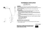
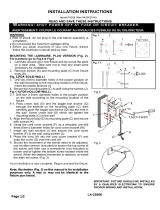
Fig.1
WARNING
:
• Risk of shock, do not plug in the unit before assembly is complete.
• Do not exceed the maximum wattage rating. (NE PAS DEPASSER LA
PUISSANCE NOMINALE MAXIMALE!)
• Before turning on, please follow the instruction manual step by step.
INSTALLATION
1.
Place all parts on a smooth, flat surface to protect the finish until ready to install.
2.
Secure handle (E) into lamp head (D).
3.
Align the holes of small glass shade (R) and large glass shade (T) onto lamp
head (D) and secure with studs (S).
4.
Attach the finial (C) to fixture body.
5.
Connect the power adapter (A) to connector (B).
IMPORTANT SAFETY INSTRUCTIONS
1. This lamp uses a touch switch. Press and release to turn on and/or off. When in
the on position, press and hold the touch switch to cycle from dim to bright.
Release the switch once desired brightness is reached
2. The LED module can be replaced by a qualified electrician without cutting of wire
and without damage to any decorative element to which the fixture is attached.
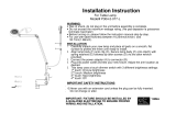
See installation steps for more details (Fig 2.)
a. Shut off the power and loosen studs (S) to remove large
glass shade (T)
and small glass shade (R) from lamp head (D).
b. Use a screw driver to loosen the screws (H) and remove the module
from white plastic ring (G).
c. Un-plug the wire quick connector with LED module (F) for re-lamping.
(Note: The LED module should be provided by specified supplier).
d. For better heat dissipation the LED module (F) should be installed with
the heat transfer material (E) when re-lamping.
LA-2480E (Date: Mar. 27, 2015)
MADE IN CHINA
IMPORTANT: FIXTURE SHOULD BE INSTALLED BY
A QUALIFIED ELECTRICIAN TO ENSURE PROPER
WIRING AND INSTALLATION.
Fig.2
D
E
F (L-L-module)
G (L
-
L
-
module
H (L-L-module screw)
R
S
T
E
C
T
S
R
D
Touch Switch
B
A
/


