Page is loading ...

337009
U.S. Patent Pending
CoolTouch
TM
control system
READ AND SAVE THESE INSTRUCTIONS
CAUTION: This control system was designed to operate and work with a specific Kichler
®
Ceiling Fan ONLY. It is not recommended for use with or installation on any other brand of
ceiling fan.
Please make sure your Kichler
®
dealer has selected the correct model CoolTouch™ control
system for your specific Kichler
®
Ceiling Fan.
Installation on ANY other brand of ceiling fan could cause the ceiling fan to operate at high
temperatures possibly damaging the motor or other components and will VOID your warranty.
By Ted Collmar at 8:08 am, Jan 04, 2010

GENERAL INFORMATION
The CoolTouch™ control system is designed to separately control
your ceiling fan speeds, reverse the blade direction and both the
down light and up light (if present on the fan).
The speed button will control each fan speed. HI, Medium, and Low
The reverse button will reverse the direction of the blades.
The off button will shut down the motor.
Each light button will separately control the Up and Down lights if
your fan is equipped with them.
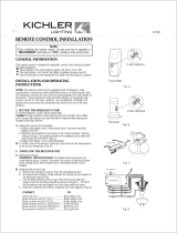
1. INSTALLATION AND OPERATING
INSTRUCTIONS
The Kichler
®
CoolTouch
™
control system is equipped with 16 code
or "Frequency" combinations to help prevent interference from or to
other remote units. The frequency switches on the receiver and
transmitter have been preset at the factory. Please recheck to make
sure both sets of switches are set in the SAME position. Any
combination of settings will operate the fan as long as the switches
on the transmitter and receiver are set in the same positions.
1. SETTING THE CODE
A. Setting the code (frequency) on the transmitter:
a. Remove the battery cover on the transmitter by pressing on the
cover lid at the point indicated in Figure A
b. Slide each switch to a UP or DOWN position (factory setting is
all UP). Each possible combination (16) of all four switches is
a unique "Frequency". Use a small screwdriver or ballpoint
pen to move the switches. (Fig. A)
c. Replace the battery cover on the transmitter.
B. Set the code (frequency) on the receiver unit by following the same
procedure as the transmitter, see figure B. Remember to MATCH the
same setting as on the transmitter.
2. INSTALLING RECEIVER IN THE CEILING FAN
WARNING: HIGH VOLTAGE ! Household electrical power can
cause serious injury or death. Make sure the electrical power source
is turned OFF at the main panel by removing the circuit fuse or
switching the circuit breaker OFF.
A. Installing the receiver unit:
a. Rotate the mounting screw cover on the canopy counter
clockwise, loosen the two mounting screws, rotate the canopy
counter clockwise and let them rest on top of the motor housing.
b. Disconnect the existing electrical wiring between the ceiling
fan and the household supply wires in the ceiling outlet box.
c. Slide the receiver unit into the open space between the top of
the mounting bracket and the mounting ball with the "flat"
side of the receiver facing UP. (Fig. C or D)
The CoolTouch™ Receiver Unit is adaptable to the Kichler
®
Basic
Mounting System (Fig. D) as well as the Kichler
®
Slope Adaptor
Mounting System (Fig. C)
Code switches
Press Here
Code switches
Mounting Screw
Cover
Receiver
Transmitter
Fig. A
Fig. B
Fig. C
Fig. D
ON
ON
1
RECEIVER
RECEIVER

3. CHANGING SWITCH HOUSINGS AND
COMPONENTS
ATTENTION: The CoolTouch™ Control System requires the
purchase of a new Switch Housing that will replace your existing
Switch Housing. Part number 370017 or 370018 depending on the
mounting plate diameter. Available in a finish to match your ceiling
fan.
1. Loosen the four (4) mounting screws located around the top edge
of the switch housing.
2. Rotate the switch housing until the mount screw heads are at the
"open" end of the key hole slots and pull the switch housing
downward. See Figure F as needed.
3. Locate the small plastic clip on the side of the square wire
connector. While pressing to hold the clip open, pull the wire
connectors apart.
4. You have remove the existing switch housing from your ceiling
fan. You won't be needing it with your new remote control
installation.
It's suggested that you keep this original switch housing and all
components inside just in case you decide to remove the
CoolTouch™ Control System at a later date.
5. Locate your NEW empty switch housing and place the
CoolTouch™ Wiring Harness inside. (Fig. G)
Fig. F
Fig. G
Switch
housing
Wire connector
Screws
Mounting plate
Reverse
module
Wiring
harness
Empty switch
housing
Capacitor
Receiver to Supply Wires: Figure E
Green fan wire to............................................Bare (copper) supply wire
Black receiver wire marked AC In L to........ Black supply wire
White receiver wire marked AC In N to........White supply wire
Receiver to Fan wires: Figure E
White receiver wire marked TO MOTOR N to..............White wire from the Fan
Black receiver wire marked TO MOTOR L to...............Black wire from the Fan
Blue receiver wire marked FOR LIGHT to.....................Blue wire from the Fan
Orange receiver wire marked FOR UPPER LIGHT to......Orange wire from the Fan
Fig. E
AC SUPPLY
BLACK
WHITE
ORANGE ORANGE
BARE
GREEN
WHITE
WHITE
BLUE BLUE
BLACK
BLACK
WHITE
BLACK
RECEIVER
OUTLET BOX
NOTE: Some ceiling fans are not equipped with a Downlight or
accent Uplight. The Blue wire on this receiver is for a Downlight
and the Orange wire is for a accent Uplight. If your ceiling fan
does not have either one or both types of lights, USE A WIRE
NUT AND CAP OFF THE WIRE(S) NOT USED.
CAUTION: If the household supply wires are a different color
than described here, it's recommended that you have a qualified
electrician make these connections.
d. Push all connected wires up into junction box.
e. Reinstall the canopy on the mounting bracket. (Fig. C)
CoolTouch
TM
control system
2

Fig. I
Light kit
assembly
Wire connector
Screws
Mounting plate
Glass
shade
Glass cap
Metal nut
Decorative nut
Bulbs
4. INSTALLING A OPTIONAL DOWNLIGHT
FIXTURE:
NOTE: If your ceiling fan is equipped with a down light, follow the
instructions below. The illustrations here are for general reference
ONLY. You should refer to the specific assembly instructions that
came with your Light Kit.
1. Remove the plastic Center Plug from the switch housing. (Fig. H)
2. Attach the light fixture to the switch housing by feeding the light
fixture wires one at a time (black and white) through the hole in
the center of the switch housing.
3. Screw the threaded pipe on the light fixture into the center hole
on the switch housing. Place a lock washer and retainer nut on
the threaded pipe from the inside of the switch housing and
tighten securely making sure it is tight enough to prevent the light
fixture from coming loose during fan operation. (Fig. H)
4. Inside the switch housing, locate the Blue and White wires on the
wiring harness marked FOR LIGHT. Connect these wires to the
light fixture wires by pushing them together until they click.
White Fixture wire to White Fan wire
Black Fixture wire to Blue Fan wire.
5. Raise and hold the light kit assembly close to the mounting plate
on the ceiling fan. Push the square wire connectors together.
(Fig. I)
NOTE: The square connectors are color coded. Match the color
coded sides of each plug and push. They will attach ONLY when
matched correctly.
6. Carefully push all wires back into the switch housing, then attach
the light kit assembly to the mounting plate by aligning the key
holes on the switch housing with the screw heads on the mounting
plate.
Rotate the light kit assembly until the screw heads are at the narrow
end of the key holes and tighten each screw.
7. Install all necessary lamps and glass shade(s) for your specific
light kit.
Fig. H
Nut
Lock washer
Light kit
Switch housing
Threaded Pipe
Center
plug
3

CoolTouch
TM
control system
4
5. TRANSMITTER PREPERATION AND OPERATION:
A. The CoolTouch™ Transmitter can be used outdoors without any
concern. However, it should be stored, while not in use, indoors and
away from excess heat or humidity.
B. Remove the back cover on the transmitter and install both, 3 volt
(#2032) batteries that were included with the remote control. Make
sure the + sign is facing up and be careful NOT to move any of the
small frequency dip switches. (Fig. J)
Replace the battery cover.
C: To prevent possible damage to the transmitter, remove these
batteries if not used for long periods of time (months).
D. Speed Control Buttons:
The " - - " buttons:
These three buttons are used to set each fan speed as follows.
Push and Release for operation.
= Low speed = Medium speed = High speed
The " " button:
This button turns the fan MOTOR off ONLY (The speed
buttons turn the motor on). Push and Release for operation.
The " " button turns the upper light ON or OFF and also
controls the brightness setting. The " " button turns the bottom
light ON or OFF and also controls the brightness setting. Press
and release the button to turn the light ON or OFF. Press and
hold the button to set the desired brightness.Each light button has
an "intelligent return" feature. Once the desired brightness level
is set and you turn that light OFF, it will return to the same level
of brightness the next time you turn the light ON. If power is lost
to the fan, this setting is lost and must be reset.
The " " button is used to set the fan in forward or reverse
operation. Each time you press and release this button, the fan
blades will reverse direction. This button functions ONLY when
the fan blades are in motion.
Fig. K
Fig. J

REMEMBER: This control system was designed to operate and work
with a specific Kichler
®
Ceiling Fan ONLY. It is not recommended for
use with or installation on any other brand of ceiling fan.
Please make sure your Kichler® dealer has selected the correct model
CoolTouch™ Control System for your specific Kichler Ceiling Fan.
WARNING: This control system is intended for use on 120 volt / 60
Hz power systems ONLY.
WARNING: The dimming function on this control system is NOT
intended for use with NON-Dimmable Fluorescent lamps.
6. INSTALLING THE COOLTOUCH™
CONTROL SYSTEM WALL PLATE
7. STORING THE TRANSMITTER
Place the transmitter in the wall pocket by inserting the bottom of the
transmitter first and then press the top of the transmitter into the pocket.
The transmitter will fully function from this location or you can remove
it to use as a "Hand Held" device.
To remove the transmitter from the wall pocket, push the release button
and the transmitter will fall into your hand.
8. TROUBLESHOOTING GUIDE
If the Ceiling Fan and or light fixture(s) fail to respond to commands
from the transmitter, check the following.
● Check the main power supply and reset or turn on the breaker.
● Make sure the "Receiver Unit" is wired properly.
● Light Fixture pull chain switch turned to ON ?
● Good batteries in transmitter ? Replace if needed.
● Transmitter and Receiver "frequency" switches set to match each
other ?
NOTE: The distance between the transmitter and receiver should not be
greater than 30 feet. For best performance, make sure the Black
Antenna on the end of the receiver unit remains extended and not
tangled with any of the electrical wires.
Select a location to install your CoolTouch™ Control System
Transmitter and Wall Pocket.
REMEMBER, you can safely use the transmitter outdoors but it should
be stored, while not is use, indoors away from excess heat or humidity.
You can replace an existing wall switch or, install the transmitter wall
pocket on ANY flat surface.
Option 1: Install the control system using an existing wall switch outlet
box. Make sure the electrical power is TURNED OFF at the main panel
before continuing.
Step 1. Remove the existing wall plate and the old switch from the wall
outlet box. Wire nut the BLACK leads (hot) together and push back
inside the outlet box. (Fig. L)
Step 2. Install the metal plate and CoolTouch™ wall plate to the existing
wall outlet box with 4 screws provided. Then place the two plastic plugs
into the wall plate. (Fig. M)
Option 2: Install the control system on ANY flat surface. Select the
desired location and use the CootTouch™ wall plate to mark the
location for the mounting holes. Plastic wall anchors and screws are
provided for this type of installation.
After installing the wall anchors, attached the CoolTouch™ wall plate
with the mounting screws and then insert the plastic plugs to finish the
installation.
Release
button
Screws
Screws
Plastic plugs
CoolTouch
™
wall plate
Outlet box
Metal plate
Fig. M
Fig. L
Fig. N
Wall plate
Switch
Outlet box
5
/