3M DBI-SALA® SecuraSpan™ Pour-in-Place/Fasten-in-Place HLL Intermediate Bracket 7400200, 1 EA Operating instructions
- Category
- Gate Opener
- Type
- Operating instructions

© Copyright 2012, DB Industries, Inc.
Fasten-In-Place Bases
Model Numbers: See Figure 1
User InstrUctIon ManUal
caPItal saFetY
This manual is intended to meet industry standards, including ANSI Z359.1, as well as local, state and federal
(OSHA1910.66, 1926.502, and CSA in Canada), and should be used as part of an employee training program as
required by OSHA.
Form: 5903293 Rev: C
WarnInG: This product is to be used as part of a complete system. These instructions must be provided to the
user of this equipment. The user must read and understand these instructions before using this equipment. The
user must follow the manufacturer’s instructions for each component of the complete system. Manufacturer’s
instructions must be followed for proper use and maintenance of this product. Alterations or misuse of this
product, or failure to follow instructions may result in serious injury or death.
IMPortant: If you have questions on the use, care, or suitability of this equipment for your application,
contact Capital Safety.
IMPortant: Before using this equipment record the product identication information from the ID label in the
Inspection and Maintenance Log of this manual.
IMPortant: Before installing this equipment make sure a qualied person veries the structural integrity
of the structure being mounted to.(See Applications, Specications, Installation details in this document for
installation instructions, mounting requirements and rated capacities of each Fasten-In-Place base model.)
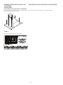
Figure 1 - Models
7400211 7400218
7400222
7400225 8530267
8530373
The Ultimate in
Fall Protection

2
1.0 APPLICATION
1.1 PURPOSE: For use with Securaspan™ Pour-In-Place Horizontal Lifeline Systems, including 7400203.
Refer to Applications, Specications and Installation details in this document for the applications of each
Fasten-In-Place base in this instruction.
1.2 LIMITATIONS:
A. PERSONAL FALL ARREST SYSTEM: PFAS’s used with this system must meet applicable OSHA, state,
federal, and ANSI requirements. PFAS’s incorporating a full body harness must be capable of arresting a
worker’s fall with a maximum arresting force appropriate for the set up of this system.
B. ENVIRONMENTAL HAZARDS: Use of this equipment in areas where environmental hazards exist
may require additonal precautions be taken to reduce the possiblity of injury to the user or damage
to the equipment. Hazards may include, but are not limited to: heat (welding, cutting), extreme cold,
caustic chemicals, corrosive environments, high voltage power lines, explosive or toxic gases, moving
machinery, or sharp edges. Contact Capital Safety if you have questions about using this equipment
where environmental hazards exist. This system cannot be used where the davit mast cannot be
perpendicular to the work surface.
C. TRAINING: This equipment must be installed and used by persons who have been properly trained in
its correct application and use. Installation and use of this equipment must be supervised by a qualified
person
1
, as defined by OSHA fall protection standards.
1.3 APPLICABLE STANDARDS: Refer to local standards,national standards, and OSHA requirements for more
information on the application of this and associated equipment.
2.0 SYSTEM LIMITATIONS & REQUIREMENTS
Always consider the following limitations/requirements when installing or using this equipment:
2.1 COMPATIBILITY OF COMPONENTS: Capital Safety equipment is designed for use with Capital Safety
approved components and subsystems only. Substitutions or replacements made with non-approved
components or subsystems may jeopardize compatibility of equipment and may effect the safety and
reliability of the complete system.
2.2 COMPATIBILITY OF CONNECTORS: Connectors are considered to be compatible with connecting
elements when they have been designed to work together in such a way that their sizes and shapes do not
cause their gate mechanisms to inadvertently open regardless of how they become oriented. Contact Capital
Safety if you have any questions about compatibility.
Connectors (hooks, carabiners, and D-rings) must be capable of supporting at least 5,000 lbs. (22.2kN).
Connectors must be compatible with the anchorage or other system components. Do not use equipment
that is not compatible. Non-compatible connectors may unintentionally disengage (see Figure 2). Connectors
must be compatible in size, shape, and strength. Self-locking snap hooks and carabiners are required by
ANSI Z359.1, OSHA and CSA Z259.12 in Canada.
2.3 MAKING CONNECTIONS: Use only self-locking snap hooks and carabiners with this equipment. Only use
connectors that are suitable to each application. Ensure all connections are compatible in size, shape and
strength. Do not use equipment that is not compatible. Ensure all connectors are fully closed and locked.
DBI-SALA connectors (snap hooks and carabiners) are designed to be used only as specied in each
product’s user’s instructions. See Figure 3 for illustration of the inappropriate connections stated below.
DBI-SALA snap hooks and carabiners should not be connected:
A. To a D-ring to which another connector is attached.
B. In a manner that would result in a load on the gate.
C. In a false engagement, where features that protrude from the snap hook or carabiner catch on the
anchor and without visual conrmation seems to be fully engaged to the anchor point.
D. To each other.
E. Directly to webbing or rope lanyard or tie-back (unless the manufacturer’s instructions for both the
lanyard and connector specically allow such a connection).
F. To any object which is shaped or dimensioned such that the snap hook or carabiner will not close and
lock, or that roll-out could occur.
1 A person with a recognized degree or professional certicate and with extensive knowledge, training, and experience in
the fall protection and rescue eld who is capable of designing, analyzing, evaluating and specifying fall protection and rescue
systems to the extent required by applicable standards.

3
G. In a manner that does not allow the connector to align with the fall arrest device (i.e., lanyard) while under
load.
NOTE: Other than 3,600 lb. (16 kN) gated hooks, large throat opening snap hooks should not be connected
to standard size D-rings or similar objects which will result in a load on the gate if the hook or D-ring twists
or rotates. Large throat snap hooks are designed for use on xed structural elements such as rebar or cross
members that are not shaped in a way that can capture the gate of the hook.
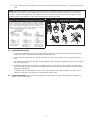
Figure 2- Unintentional Disengagement (Rollout)
If the connecting element to which a snap hook (shown) or carabiner
attaches is undersized or irregular in shape, a situation could occur
where the connecting element applies a force to the gate of the snap
hook or carabiner. This force may cause the gate (of either a self-
locking or a non-locking snap hook) to open, allowing the snap hook
or carabiner to disengage from the connecting point.
Small ring or other
non-compatibly
shaped element
1. Force is applied to
the Snap Hook.
2. The Gate presses
against the
Connecting Ring.
3. The Gate opens
allowing the Snap
Hook to slip off.
Figure 3 - Inappropriate Connections
2.4 OTHER RESTRICTIONS:
• Do not make connections where the hook locking mechanism can come into contact with a structural
member or other equipment and potentially release the hook.
• Do not connect a snap hook into a loop or thimble of a wire rope or attach in any way to a slack wire
rope.
• The snap hook must be free to align with the applied load as intended (regardless of the size or shape of
the mating connector).
• A carabiner may be used to connect to a single or pair of soft loops on a body support such as a body
belt or full body harness, provided the carabiner can fully close and lock. This type of connection is not
allowed for snap hooks.
• A carabiner may be connected to a loop or ring connector that is already occupied by a choker style
connector. This type of connection is not allowed for snap hooks.
2.5 STRUCTURE LOAD: Structure load requirements for each Fasten-In-Place base model are described in
Section 7 of this instruction.

4
3.0 SYSTEM USE
WARNING: Do not alter or intentionally misuse this equipment. Consult Capital Safety when using this
equipment in combination with components or subsystems other than those described in this manual. Some
subsystem and component combinations may interfere with the operation of this equipment. Use caution when
using this equipment around moving machinery, electrical hazards, chemical hazards, and sharp edges.
3.1 BODY SUPPORT: When using this Capital Safety system it is recommended that a full body harness be
worn. For general fall protection use, connect to the D-ring on the back between the shoulders (Dorsal
D-ring).
3.2 NORMAL OPERATION: If a fall has been arrested, the system must be taken out of service and inspected, see
Section 5.0
.
4.0 TRAINING
4.1 It is the responsiblity of all users of this equipment to understand these instructions, and are trained in
the correct installation, use, and maintenance of this equipment. These individuals must be aware of the
consequences of improper installation or use of this equipment. This user manual is not a substitute for a
comprehensive training program. Training must be provided on a periodic basis to ensure prociency of the
users.
5.0 INSPECTION
5.1 BEFORE EACH INSTALLATION: Inspect this system and other system components according to these
or other manufacturer’s instructions. System components must be formally inspected by a qualied
person (other than the user) at least annually. Formal inspections should concentrate on visible signs of
deterioration or damage to the system components. Items found to be defective must be replaced. Do not
use components if inspection reveals an unsafe or defective condition. Record results of each inspection in
the Inspection and Maintenance Log in this manual.
IMPORTANT: If this equipment has been subjected to forces resulting from the arrest of a fall, it must be
immediately removed from service and destroyed or returned to Capital Safety for possible repair.
5.2 INSPECTION STEPS:
Step 1: Ensure the system is free of cracks, dents, distortion, or any other damage.
Step 2: Inspect for corrosion or rust
Step 3: All labels must be present and fully legible.
5.2 If inspection reveals an unsafe or defective condition, remove the unit from service and destroy, or contact
Capital Safety for possible repair.
5.2 USER EQUIPMENT: Inspect each system component or subsytem (i.e. SRL, full body harness, lanyard,
lifeline, etc.) per associated manufacturer’s instructions. Refer to manufacturer’s instruction supplied with
each system component for inspection procedure.
6.0 MAINTENANCE, SERVICE, AND STORAGE
6.1 If components become heavily soiled with grease, paint, or other substances, clean with appropriate
cleaning solutions. Do not use caustic chemicals that could damage system components.
7.0 FASTEN-IN-PLACE BASE MODELS IN THIS INSTRUCTION
• 8530373 Fasten-In-Place Clamp-On Vertical Base
• 7400211 Fasten-In-Place Clamp-On Vertical Base
• 7400218 Fasten-In-Place Bolt-On Vertical Base
• 7400222 Fasten-In-Place Weld-On Vertical Base
• 7400225 Fasten-In-Place Bolt-On Vertical Base
• 8530267 Fasten-In-Place Bolt-On Floor Base

5
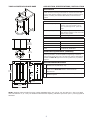
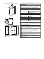
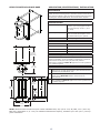
7400211 FASTEN-IN-PLACE BASE APPLICATION, SPECIFICATIONS, INSTALLATION
APPLICATION
The 7400211 Fasten-In-Place Clamp-On Vertical Base is designed
to bolt around an existing vertical steel or concrete structure and
is to be used with Securaspan™ Fasten-In-Place Horizontal Lifeline
Systems, including the 7400203 DBI-SALA
®
Horizontal Lifeline
System.
SPECIFICATIONS
Dimensional Capacity Fits up to 6.72 in. (17.1 cm) wide X
12.22 in. (31.0 cm) high X 5.50 in.
(14.0 cm) through 6.5 in. (16.5 cm)
deep.
System Capacity 310 lbs (141 kg) for each person when
used with Securaspan™ Post Horizontal
Lifeline (HLL) system.
Weight 80 lbs. (36 Kg)
MATERIALS AND CONSTRUCTION
General Construction Welded Steel
Weld Certification AWS
Structure Material A-36 Steel Plate
Finish Zinc Plate Per ASTM B633
MOUNTING REQUIREMENTS (MINIMUM)
The structure and mounting hardware (base 7400211 includes
mounting hardware) must be capable of supporting a minimum
moment load of 390,000 in*lb. (44,064 N*m) without deformation.
Installation MUST BE approved to local regulations by a qualified
engineer.
APPLICATION RESTRICTIONS
1. Bases are for use with Securaspan™ posts and accessories
manufactured by DBI-SALA
®
only.
2. If structure material does not meet minimum requirements,
reinforcement MUST BE added to meet mimimum
requirements.
3. Each installation MUST BE approved to local regulations by a
qualified engineer.
5.5 in
13.9 cm
10 in
25.4 cm
16 in
40.6 cm
7.5 in
19.1 cm
2 in
5.1 cm
.5 in / 13 mm
6.50 in
16.5 cm
See Note
12.22 in
31.0 cm
6.72 in
17.0 cm
NOTE: 7400211 base includes four part number 8526654 bolts, HH, 3/4-10 X 9, ZP, GR8, 9 in. (22.9 cm). Bolt
end is threaded 2 in. (5.1 cm). For additional dimensional capacity, substitute your own 3/4 in. (19 mm) grade 8
hardware.

6
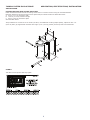
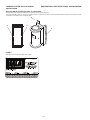
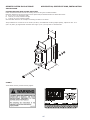
7400211 FASTEN-IN-PLACE BASE APPLICATION, SPECIFICATIONS, INSTALLATION
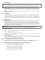
INSTALLATION
FASTEN STANCHION BASE AROUND STRUCTURE:
Fasten the Stanchion Base around an existing vertical steel or concrete structure using the included hardware.
Maximum dimensions of structure that can be captured by the 7400211 Fasten-In-Place base frame:
A. 6.72 in (17.1 cm) maximum width
B. 12.22 in (31.0 cm) maximum height
C. 6.50 in (16.5 cm) maximum depth
See illustration below.
Torque hardware to a minimum of 130 ft*lbs (176 N*m). For additional mounting depth capacity, replace the four 9 in.
(22.9 cm) bolts (D) supplied with the base with longer 3/4 in. (19 mm) grade 8 (minimum) bolts or threaded rods.
A
B
C
D
LABELS
This label must be present and fully legible:

7
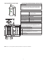
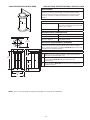
7400218 FASTEN-IN-PLACE BASE APPLICATION, SPECIFICATIONS, INSTALLATION
APPLICATION
The 7400218 Fasten-In-Place Bolt-On Vertical Base is designed
to bolt to an existing vertical steel or concrete structure and is
to be used with Securaspan™ Fasten-In-Place Horizontal Lifeline
Systems, including the 7400203 DBI-SALA
®
Horizontal Lifeline
System.
SPECIFICATIONS
System Capacity 310 lbs (141 kg) for each person when
used with Securaspan™ Post Horizontal
Lifeline (HLL) system.
Weight 24 lbs. (11 Kg)
MATERIALS AND CONSTRUCTION
General Construction Welded Steel
Weld Certification AWS
Structure Material A-36 Steel Plate
Finish Zinc Plate Per ASTM B633
MOUNTING REQUIREMENTS (MINIMUM)
The structure and mounting hardware must be capable of
supporting a minimum moment load of 390,000 in*lb. (44,064
N*m) without deformation. Installation MUST BE approved to local
regulations by a qualified engineer.
APPLICATION RESTRICTIONS
1. Bases are for use with Securaspan™ posts and accessories
manufactured by DBI-SALA
®
only.
2. If structure material does not meet minimum requirements,
reinforcement MUST BE added to meet mimimum
requirements.
3. Each installation MUST BE approved to local regulations by a
qualified engineer.
5.5 in
13.9 cm
10 in
25.4 cm
16 in
40.6 cm
7.5 in
19.1 cm
2 in
5.1 cm
.5 in / 13 mm
13 in
33.0 cm
7.5 in
19.1 cm
NOTE: 3/4 in. (19 mm) grade 8 (minimum) hardware is required for installation.

8
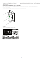
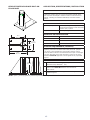
7400218 FASTEN-IN-PLACE BASE APPLICATION, SPECIFICATIONS, INSTALLATION
INSTALLATION
FASTEN THE BOLT-ON VERTICAL BASE TO STRUCTURE:
Fasten the Stanchion Base to an existing vertical steel or concrete structure using 3/4 in. (19 mm) grade 8 (minimum)
hardware (not included).
See illustration below. Torque hardware to a minimum of 130 ft*lbs (176 N*m).
LABELS
This label must be present and fully legible:

9
7400222 FASTEN-IN-PLACE BASE APPLICATION, SPECIFICATIONS, INSTALLATION
APPLICATION
The 7400222 Fasten-In-Place Weld-On Vertical Base is designed to
be welded to an existing vertical steel structure and is to be used
with Securaspan™ Fasten-In-Place Horizontal Lifeline Systems,
including the 7400203 DBI-SALA
®
Horizontal Lifeline System.
SPECIFICATIONS
System Capacity 310 lbs (141 kg) for each person when
used with Securaspan™ Post Horizontal
Lifeline (HLL) system.
Weight 50 lbs. (23 Kg)
MATERIALS AND CONSTRUCTION
General Construction Welded Steel
Weld Certification AWS
Structure Material A-36 Steel Plate
Finish Zinc Plate Per ASTM B633
MOUNTING REQUIREMENTS (MINIMUM)
The structure and mounting hardware must be capable of
supporting a minimum moment load of 390,000 in*lb. (44,064
N*m) without deformation. Installation MUST BE approved to local
regulations by a qualified engineer.
APPLICATION RESTRICTIONS
1. Bases are for use with Securaspan™ posts and accessories
manufactured by DBI-SALA
®
only.
2. System design factor depends on other system components
and the configuration in which they are assembled. The
minimum design factor for all standard Advanced Safety
Systems masts and accessories is 4:1.
3. All welding is to be carried out by qualified personnel.
4. If structure material does not meet minimum requirements,
reinforcement MUST BE added to meet mimimum
requirements.
5. Each installation MUST BE approved to local regulations by a
qualified engineer.
5.5 in
13.9 cm
6 in
15.2 cm
11 in
27.9 cm
9.25 in
23.5 cm
.5 in / 13 mm
2.25 in
5.7 cm
1.25 in / 3.2 cm

10
7400222 FASTEN-IN-PLACE BASE APPLICATION, SPECIFICATIONS, INSTALLATION
INSTALLATION
WELD THE WELD-ON VERTICAL BASE TO STRUCTURE:
The Weld-On Base must be welded to an existing vertical steel structure.
The weld bead (A) must run the entire length of both C-Channels as shown in the illustration below. Weld must be able to hold
a 390,000 in lb (4,407 N*m) moment load.
A
A
A
A
LABELS
This label must be present and fully legible:

11
7400225 FASTEN-IN-PLACE BASE APPLICATION, SPECIFICATIONS, INSTALLATION
APPLICATION
The 7400225 Fasten-In-Place Bolt-On Vertical Base is designed
to bolt to an existing vertical steel or concrete structure and is
to be used with Securaspan™ Fasten-In-Place Horizontal Lifeline
Systems, including the 7400203 DBI-SALA
®
Horizontal Lifeline
System.
SPECIFICATIONS
System Capacity 310 lbs (141 kg) for each person when
used with Securaspan™ Post Horizontal
Lifeline (HLL) system.
Weight 24 lbs. (11 Kg)
MATERIALS AND CONSTRUCTION
General Construction Welded Steel
Weld Certification AWS
Structure Material 304 Stainless Steel
MOUNTING REQUIREMENTS (MINIMUM)
The structure and mounting hardware must be capable of
supporting a minimum moment load of 390,000 in*lb. (44,064
N*m) without deformation. Installation MUST BE approved to local
regulations by a qualified engineer.
APPLICATION RESTRICTIONS
1. Bases are for use with Securaspan™ posts and accessories
manufactured by DBI-SALA
®
only.
2. If structure material does not meet minimum requirements,
reinforcement MUST BE added to meet mimimum
requirements.
3. Each installation MUST BE approved to local regulations by a
qualified engineer.
5.5 in
13.9 cm
10 in
25.4 cm
16 in
40.6 cm
7.5 in
19.1 cm
2 in
5.1 cm
.5 in / 13 mm
13 in
33.0 cm
7.5 in
19.1 cm
NOTE: 3/4 in. (19 mm) grade 8 (minimum) hardware is required for installation.

12
7400225 FASTEN-IN-PLACE BASE APPLICATION, SPECIFICATIONS, INSTALLATION
INSTALLATION
FASTEN THE BOLT-ON VERTICAL BASE TO STRUCTURE:
Fasten the Stanchion Base to an existing vertical steel or concrete structure using 3/4 in. (19 mm) grade 8 (minimum)
hardware (not included).
See illustration below. Torque hardware to a minimum of 130 ft*lbs (176 N*m).
LABELS
This label must be present and fully legible:

13
8530267 FASTEN-IN-PLACE BOLT-ON
FLOOR BASE
APPLICATION, SPECIFICATIONS, INSTALLATION
APPLICATION
The 8530267 Fasten-In-Place Bolt-On Floor Base is designed to
be bolted to existing steel or concrete horizontal surfaces and is
to be used with Securaspan™ Fasten-In-Place Horizontal Lifeline
Systems, including the 7400203 DBI-SALA
®
Horizontal Lifeline
System.
SPECIFICATIONS
System Capacity 310 lbs (141 kg) for each person when
used with Securaspan™ Post Horizontal
Lifeline (HLL) system.
Weight 75 lbs. (34 Kg)
MATERIALS AND CONSTRUCTION
General Construction Welded Steel
Weld Certification AWS
Structure Material A-36 Steel Plate
Finish Zinc Plate Per ASTM B633
MOUNTING REQUIREMENTS (MINIMUM)
The structure and mounting hardware must be capable of
supporting a minimum moment load of 390,000 in*lb. (44,064
N*m) and a 5,000 lb (2268 kg) vertical load. Anchors used to
mount this base must have an installed minimum pull-out strength
of 19,500 (86.8 kN) and a shear strength of 5,000 lb (22.2 kN).
Installation MUST BE approved to local regulations by a qualified
engineer.
APPLICATION RESTRICTIONS
1. Bases are for use with Securaspan™ posts and accessories
manufactured by DBI-SALA
®
only.
2. If structure material does not meet minimum requirements,
reinforcement MUST BE added to meet mimimum
requirements.
3. Each installation MUST BE approved to local regulations by a
qualified engineer.
15.5 in
39.4 cm
2 in
5.1 cm
18 in
45.7 cm
12.0 in
30.5 cm
14 in
35.6 cm
8.0 in
20.3 cm
NOTE: 3/4 in. (19 mm) grade 8 (minimum) hardware is required for installation.

14
8530267 FASTEN-IN-PLACE BOLT-ON
FLOOR BASE
APPLICATION, SPECIFICATIONS, INSTALLATION
INSTALLATION
BOLT THE BOLT-ON FLOOR BASE TO STRUCTURE:
Fasten the Bolt-On Floor Base around an existing steel or concrete horizontal surface using 3/4 in. (19 mm) grade 8
(minimum) hardware (not included).
LABELS
This label must be present and fully legible:

15
8530373 FASTEN-IN-PLACE BASE APPLICATION, SPECIFICATIONS, INSTALLATION
APPLICATION
The 8530373 Fasten-In-Place Clamp-On Vertical Base is designed
to bolt around an existing steel or concrete structure and is to be
used with Securaspan™ Pour-In-Place Horizontal Lifeline Systems,
including the 7400203 DBI-SALA
®
Horizontal Lifeline System.
SPECIFICATIONS
Dimensional Capacity Fits up to 8.13 in. (20.1 cm) wide X
12.22 in. (31.0 cm) high X 10.94 in.
(27.8 cm) through 11.94 in. (30.3
cm) deep.
System Capacity 310 lbs (141 kg) for each person
when used with Securaspan™ Post
Horizontal Lifeline (HLL) system.
Weight 85 lbs. (39 Kg)
MATERIALS AND CONSTRUCTION
General Construction Welded Steel
Weld Certification AWS
Structure Material A-36 Steel Plate
Finish Zinc Plate Per ASTM B633
MOUNTING REQUIREMENTS (MINIMUM)
The structure and mounting hardware (base 8530373 includes
mounting hardware) must be capable of supporting a minimum
moment load of 390,000 in*lb. (44,064 N*m) without
deformation. Installation MUST BE approved to local regulations
by a qualified engineer.
APPLICATION RESTRICTIONS
1. Bases are for use with Securaspan™ posts and accessories
manufactured by DBI-SALA
®
only.
2. If structure material does not meet minimum requirements,
reinforcement MUST BE added to meet mimimum
requirements.
3. Each installation MUST BE approved to local regulations by
a qualified engineer.
5.5 in
13.9 cm
10 in
25.4 cm
16 in
40.6 cm
7.5 in
19.1 cm
2 in
5.1 cm
.5 in / 13 mm
11.94 in
30.3 cm
(See Note)
12.22 in
31.0 cm
8.13 in
20.1 cm
NOTE: 8530373 base includes four part number 9506699 bolts, HH, 3/4-10 X 15, ZP, GR8, 15 in. (38.1 cm).
Bolt end is threaded 2 in. (5.1 cm). For additional dimensional capacity, substitute your own 3/4 in. (19 mm)
grade 8 hardware.

16
8530373 FASTEN-IN-PLACE BASE APPLICATION, SPECIFICATIONS, INSTALLATION
INSTALLATION
FASTEN STANCHION BASE AROUND STRUCTURE:
Fasten the Stanchion Base around the existing structure using the included hardware.
Maximum dimensions of structure that can be captured by the 8530373 Fasten-In-Place base frame:
A. 8.13 in (20.1 cm) maximum width
B. 12.22 in (31.0 cm) maximum height
C. 11.94 in (30.3 cm) maximum depth
See illustration below for an example of mounting the base to an ibeam.
Torque hardware to a minimum of 130 ft*lbs (176 N*m). For additional mounting depth capacity, replace the four 15 in.
(38.1 cm) bolts (D) supplied with the base with longer 3/4 in. (19 mm) bolts or threaded rods.
A
B
C
D
LABELS
These labels must be present and fully legible:

17
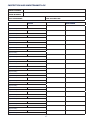
INSPECTION AND MAINTENANCE LOG
SERIAL NUMBER:
MODEL NUMBER:
DATE PURCHASED: DATE OF FIRST USE:
INSPECTION DATE INSPECTION ITEMS
NOTED
CORRECTIVE ACTION MAINTENANCE
PERFORMED
Approved By:
Approved By:
Approved By:
Approved By:
Approved By:
Approved By:
Approved By:
Approved By:
Approved By:
Approved By:
Approved By:
Approved By:
Approved By:
Approved By:
Approved By:
Approved By:
Approved By:
Approved By:
Approved By:

18
INSPECTION DATE INSPECTION ITEMS
NOTED
CORRECTIVE ACTION MAINTENANCE
PERFORMED
Approved By:
Approved By:
Approved By:
Approved By:
Approved By:
Approved By:
Approved By:
Approved By:
Approved By:
Approved By:
Approved By:
Approved By:
Approved By:
Approved By:
Approved By:
Approved By:
Approved By:
Approved By:
Approved By:
Approved By:
Approved By:
Approved By:
Approved By:

19

LIMITED LIFETIME WARRANTY
Warranty to End User: D B Industries, Inc., dba CAPITAL SAFETY USA (“CAPITAL SAFETY”) warrants to the
original end user (“End User”) that its products are free from defects in materials and workmanship under
normal use and service. This warranty extends for the lifetime of the product from the date the product is
purchased by the End User, in new and unused condition, from a CAPITAL SAFETY authorized distributor.
CAPITAL SAFETY’S entire liability to End User and End User’s exclusive remedy under this warranty is limited
to the repair or replacement in kind of any defective product within its lifetime (as CAPITAL SAFETY in its sole
discretion determines and deems appropriate). No oral or written information or advice given by CAPITAL
SAFETY, its distributors, directors, ocers, agents or employees shall create any dierent or additional
warranties or in any way increase the scope of this warranty. CAPITAL SAFETY will not accept liability for defects
that are the result of product abuse, misuse, alteration or modication, or for defects that are due to a failure to
install, maintain, or use the product in accordance with the manufacturer’s instructions.
CAPITAL SAFETY’S WARRANTY APPLIES ONLY TO THE END USER. THIS WARRANTY IS THE ONLY WARRANTY
APPLICABLE TO OUR PRODUCTS AND IS IN LIEU OF ALL OTHER WARRANTIES AND LIABILITIES, EXPRESSED
OR IMPLIED. CAPITAL SAFETY EXPRESSLY EXCLUDES AND DISCLAIMS ANY IMPLIED WARRANTIES OF
MERCHANTABILITY OR FITNESS FOR A PARTICULAR PURPOSE, AND SHALL NOT BE LIABLE FOR INCIDENTAL,
PUNITIVE OR CONSEQUENTIAL DAMAGES OF ANY NATURE, INCLUDING WITHOUT LIMITATION, LOST PROFITS,
REVENUES, OR PRODUCTIVITY, OR FOR BODILY INJURY OR DEATH OR LOSS OR DAMAGE TO PROPERTY, UNDER
ANY THEORY OF LIABILITY, INCLUDING WITHOUT LIMITATION, CONTRACT, WARRANTY, STRICT LIABILITY, TORT
(INCLUDING NEGLIGENCE) OR OTHER LEGAL OR EQUITABLE THEORY.
ISO
9001
CSG USA & Latin America
3833 SALA Way
Red Wing, MN 55066-5005
Toll Free: 800.328.6146
Phone: 651.388.8282
Fax: 651.388.5065
solutions@capitalsafety.com
CSG Canada
260 Export Boulevard
Mississauga, ON L5S 1Y9
Phone: 905.795.9333
Toll-Free: 800.387.7484
Fax: 888.387.7484
info.ca@capitalsafety.com
CSG Northern Europe
5a Merse Road
North Moons, Moat
Reditch, Worcestershire, UK
B98 9HL
Phone: + 44 (0)1527 548 000
Fax: + 44 (0)1527 591 000
csgne@capitalsafety.com
CSG EMEA
(Europe, Middle East, Africa)
Le Broc Center
Z.I. 1ère Avenue
5600 M B.P. 15 06511
Carros
Le Broc Cedex
France
Phone: + 33 4 97 10 00 10
Fax: + 33 4 93 08 79 70
information@capitalsafety.com
CSG Australia & New Zealand
95 Derby Street
Silverwater
Sydney NSW 2128
AUSTRALIA
Phone: +(61) 2 8753 7600
Toll-Free : 1 800 245 002 (AUS)
Toll-Free : 0800 212 505 (NZ)
Fax: +(61) 2 8753 7603
sales@capitalsafety.com.au
CSG Asia
Singapore:
16S, Enterprise Road
Singapore 627666
Phone: +65 - 65587758
Fax: +65 - 65587058
inquiry@capitalsafety.com
Shanghai:
Rm 1406, China Venturetech Plaza
819 Nan Jing Xi Rd,
Shanghai 200041, P R China
Phone: +86 21 62539050
Fax: +86 21 62539060
www.capitalsafety.com
The Ultimate in Fall Protection
-
 1
1
-
 2
2
-
 3
3
-
 4
4
-
 5
5
-
 6
6
-
 7
7
-
 8
8
-
 9
9
-
 10
10
-
 11
11
-
 12
12
-
 13
13
-
 14
14
-
 15
15
-
 16
16
-
 17
17
-
 18
18
-
 19
19
-
 20
20


3M DBI-SALA® SecuraSpan™ Pour-in-Place/Fasten-in-Place HLL Intermediate Bracket 7400200, 1 EA Operating instructions
- Category
- Gate Opener
- Type
- Operating instructions
Ask a question and I''ll find the answer in the document
Finding information in a document is now easier with AI
Related papers
-
DBI-SALA DBI-SALA® Confined Space Manhole Collar Davit Base 8510457, 1 EA User manual
-
3M DBI-SALA® FlexiGuard™ Trailer Mount System 8530690, 1 EA Operating instructions
-
-
3M DBI-SALA® Confined Space Bare Steel Uni-Anchor Operating instructions
-
-
-
-
-
-
Other documents
-
 Mutual Industries 15903-2 Operating instructions
-
Displays2go FGICCSWH2 Operating instructions
-
Guardian Warning Flag Line Operating instructions
-
 Mutual Industries 15903-1-30 Operating instructions
-
DBI SALA Sayfline 7603160 User Instruction Manual
-
 DBI/Sala Water Dispenser 2100090 User manual
-
Quick Dam QDFG35 User manual
-
Anova STXTG9648IM Installation guide
-
-
 MGF Counterbalance Davit System / Rescue Winch System User guide


