
5877_002-631e-06.23
Instruction
Manual
maXYmos TL
Type 5877…
ä
Valid for
Firmware Version 1.8.x

5877_002-631e-06.23 Page 1
Foreword
The information contained in this instruction manual as well as that in the corresponding
extensive instruction manual is subject to change without notice. In its pursuit of continuous
technological progress, Kistler reserves the right to modify or improve its products without
obligation to notify any person or organization of such modifications or improvements.
Kistler does not accept any liability other than that specifically required by law for the con-
sequences of this instruction manual not being followed or of this equipment being used in
conjunction with other products not listed under Accessories.
©2013 ... 2023 Kistler Group. All rights reserved. Except as expressly provided herein, no part
of this manual may be reproduced for any purpose without the express prior written consent
of Kistler Group.
Kistler Group
Eulachstrasse 22
8408 Winterthur
Switzerland
Phone +41 52 224 11 11
Fax +41 52 224 14 14
info@kistler.com
www.kistler.com

Page 2 5877_002-631e-06.23
maXYmos TL, Type 5877...
Inhalt
1. Important notes ............................................................................................................................... 10
1.1 For your safety ....................................................................................................................... 10
1.2 Unpacking ............................................................................................................................. 10
1.3 Transportation and storage..................................................................................................... 10
1.4 Supply .................................................................................................................................... 10
1.5 Electromagnetic compatibility (EMC) ...................................................................................... 11
1.6 Disposal ................................................................................................................................. 11
1.7 Care/Handling of the MEM and DIM ..................................................................................... 11
2. Short description .............................................................................................................................. 12
3. At a glance ....................................................................................................................................... 14
3.1 Table of contents "At a Glance" ............................................................................................. 15
4. Quick Start: Initial curve capture (short guide)................................................................................. 16
4.1 Installation/Mounting ............................................................................................................ 16
4.2 Sensors .................................................................................................................................. 16
4.3 Connecting to power supply/startup ...................................................................................... 16
4.4 Configure basic setup parameters........................................................................................... 17
4.5 Before making your first measurement ................................................................................... 18
4.6 Configuring measurement Channel X (Global) ....................................................................... 18
4.7 Configuring measurement Channel Y (Global) ....................................................................... 19
4.8 Configuring cycle control ...................................................................................................... 20
4.9 Capturing measurement curve ............................................................................................... 21
5. Device structure ............................................................................................................................... 22
5.1 Menu structure – The three main levels .................................................................................. 22
5.2 Parameter structure – Parameters and their storage locations ................................................. 23
6. PROCESS Menus – information pages on process status ................................................................. 24
6.1 Main page for PROCESS menu level ...................................................................................... 24
6.2 Directly selecting/Scrolling through PROCESS info pages ....................................................... 25
6.3 Overview of tool buttons ....................................................................................................... 26
6.3.1 PROCESS information pages: Traffic lights display ................................................... 27
6.3.2 PROCESS info pages: Statistics/bar charts/trend display .......................................... 28
6.3.3 PROCESS info pages: Process values ....................................................................... 29
6.3.4 PROCESS info pages: Instant view .......................................................................... 29
6.3.5 PROCESS info pages: History curves ....................................................................... 30
6.3.6 PROCESS info pages: Page selection ....................................................................... 30
6.3.7 PROCESS info pages: Full screen/screenshot/editor views ....................................... 31
6.3.8 PROCESS info pages – Warnings and Alarms .......................................................... 32
6.3.9 PROCESS info pages: Displaying values below graphs ............................................. 34
6.3.10 PROCESS info pages: Split view / displaying oher MEMs ........................................ 36
6.3.11 PROCESS info – checking/resetting piece counter ................................................... 40
6.3.12 Configuring PROCESS MP (Measurement Program) by hand .................................. 41
6.3.13 PROCESS info pages: Axis scaling ........................................................................... 42
7. SETUP Menu ................................................................................................................................... 43
7.1 Submenus/Parameter configuration paths .............................................................................. 43
7.2 SETUP Menu: Configuring the monitor's parameters ............................................................. 44
7.2.1 Opening the SETUP Menu ...................................................................................... 44
7.2.2 Inputting one or more values................................................................................... 45
7.3 Choosing the language .......................................................................................................... 46
7.4 Setting the Date + Time ......................................................................................................... 47
7.5 Access protection ................................................................................................................... 48
7.5.1 User groups access rights......................................................................................... 53
7.6 Backup + Restore functions using a USB Stick ........................................................................ 55
7.6.1 Partial restore of a backup ....................................................................................... 56
7.7 Configuring measurement Channels X and Y ......................................................................... 57

5877_002-631e-06.23 Page 3
7.7.1 "Global" configuration of Channel X or Channel Y ................................................. 57
7.7.2 "Global" settings channel X (e.g. displacement channel) ......................................... 57
7.7.3 «Global» config. Channel Y (e.g. force channel) ...................................................... 60
7.7.4 Channel X ............................................................................................................... 65
7.7.4.1 Select Channel X sensor type ............................................................................ 65
7.7.4.2 Channel X sensor type: ±10 V ........................................................................... 66
7.7.4.3 Channel X sensor type: Potentiometer .............................................................. 66
7.7.4.4 Channel X sensor type: LVDT ............................................................................ 67
7.7.4.5 Channel X sensor type: Inductive half bridge .................................................... 68
7.7.4.6 Channel X sensor type: Incremental TTL ........................................................... 69
7.7.4.7 Referencing ...................................................................................................... 70
7.7.4.8 Channel X sensor type: Incremental Sin/Cos ..................................................... 71
7.7.4.9 Channel X sensor type: SSI ................................................................................ 72
7.7.4.10 Channel-X sensor type: rotational speed ........................................................... 73
7.7.4.11 Channel X setting 'Range/Scaling' .................................................................... 74
7.7.4.12 Channel X setting "Range/Scaling" for rotational speed ................................... 75
7.7.4.13 Channel X setting 'Extra' ................................................................................... 76
7.7.4.14 Principle of two-point scaling, f.e. potentiometer .............................................. 78
7.7.5 Channel Y ............................................................................................................... 79
7.7.5.1 Select Channel Y sensor type ............................................................................ 79
7.7.5.2 Channel Y sensor type piezo ............................................................................. 80
7.7.5.3 Channel Y sensor type strain gauge .................................................................. 82
7.7.5.4 Channel Y sensor type ±10 V ............................................................................ 84
7.7.5.5 Channel Y sensor type ±10 V (2 measurement ranges) ..................................... 84
7.8 Configuring cycle control ....................................................................................................... 87
7.8.1 What is a cycle? ...................................................................................................... 87
7.8.2 Configuring GLOBAL or MP-specific cycle control ................................................... 88
7.8.3 Global cycle control configuration - Access and Menus ........................................... 89
7.8.4 Cycle control - Detailed parameter descriptions ....................................................... 92
7.8.4.1 Specifying measurement functions - the differences .......................................... 92
7.8.4.2 Specifying Delta-X ............................................................................................ 94
7.8.4.3 Specifying the START- / STOP condition ........................................................... 95
7.8.4.4 Using an external signal to control START and STOP ........................................ 95
7.8.4.5 Using measurands to control START-STOP ........................................................ 96
7.8.4.6 Examples of START-STOP combinations .......................................................... 100
7.8.4.7 START-STOP for Y(t) piezoelectric sensor ........................................................ 101
7.8.4.8 Dividing the curve into sections - Specifying the turning point ........................ 104
7.8.4.9 Truncating the measurement curve ................................................................. 109
7.9 Extras ................................................................................................................................... 110
7.9.1 Permanent storage of piece count/statistical data .................................................. 110
7.9.2 Extras "Connections" ............................................................................................ 111
7.9.2.1 Extras "Connection" and Web-UI ................................................................... 112
7.9.3 Extras "Audit & Logging" ..................................................................................... 113
7.9.3.1 Logfile parameter changes .............................................................................. 114
7.9.3.2 Audit Trail logging .......................................................................................... 116
7.9.3.3 Activate Temporary Audit Trail (maXYmos TL ML) .......................................... 117
7.9.4 HYSTERESIS settings for switch signals & trigger-Y (Global)................................... 118
7.10 Specifying the process view .................................................................................................. 120
7.10.1 "Current curve" process view ................................................................................ 121
7.10.2 "Statistics" process view........................................................................................ 122
7.10.2.1 Capture only first NOK EO for bar chart/bargraph .......................................... 122
7.10.3 "History curves" process view ............................................................................... 123
7.10.4 "Traffic light" process view ................................................................................... 123
7.10.4.1 The "capture only the first NOK EO for statistics" parameter ......................... 124
7.11 Setting up data export – from the maXYmos TL ................................................................... 126
7.11.1 PVT Export ............................................................................................................ 128

Page 4 5877_002-631e-06.23
maXYmos TL, Type 5877...
7.12 Setting up Q-DAS® data export – from the maXYmos ......................................................... 129
7.12.1 Q-DAS® Data export ............................................................................................ 130
7.12.2 Define Q-DAS® Key ............................................................................................ 131
7.12.2.1 Add key to Q-DAS® protokol ......................................................................... 132
7.12.2.2 Edit Q-DAS® key value ................................................................................... 132
7.12.2.3 Automated key values .................................................................................... 132
7.12.2.4 Edit zhe K2xxx key contents ........................................................................... 133
7.13 QDA9-Setting up data export – maXYmos .......................................................................... 134
7.14 I-P.M 5.0 – maXYmos side ................................................................................................... 138
7.15 QualityWorX – Interface ...................................................................................................... 139
7.15.1 QualityWorX – Interface MP bezogene Einstellungen ............................................ 140
7.16 Standard protocols Web server (SOAP) ................................................................................ 141
7.17 Standard protocols Server ..................................................................................................... 142
7.18 Configuring Digital IOs ........................................................................................................ 143
7.19 Configuring the fieldbus ....................................................................................................... 145
7.20 Configuring Alarms and warnings ........................................................................................ 147
7.21 Display + Audio settings ....................................................................................................... 149
7.22 Configuring (station) Name .................................................................................................. 150
7.23 Network ............................................................................................................................... 151
7.24 Universal variable table ........................................................................................................ 152
7.25 OPC UA ............................................................................................................................... 153
7.25.1 Licensing required for OPC UA functionality ......................................................... 153
7.25.2 Cycle data “Cycle DoneEvent” .............................................................................. 154
7.25.3 OPC UA Interfaces maXYmos ............................................................................... 154
7.25.4 OPC UA function and access authorization ........................................................... 155
7.26 Printer .................................................................................................................................. 156
7.27 Manage certificates .............................................................................................................. 157
7.28 Measurement program (MP) specific setup .......................................................................... 158
7.28.1 Accessing MP-specific setup .................................................................................. 158
7.29 Editing EOs (evaluation objects) ........................................................................................... 159
7.29.1 Overview of tool buttons in EO editor (part 1) ...................................................... 159
7.29.2 Overview of tool buttons in EO editor (part 2) ...................................................... 160
7.29.3 Overview of tool buttons in EO editor (part 3) ...................................................... 161
7.30 Overview of available evaluation object types ...................................................................... 162
7.30.1 Setting up EOs / Initial curve capture .................................................................... 164
7.30.2 Setting up EOs (example) ...................................................................................... 165
7.30.3 Configuring reference points for curves and EOs ................................................... 168
7.30.3.1 How do the various reference points differ from each other? .......................... 168
7.30.3.2 ABSOLUTE static EO reference point .............................................................. 169
7.30.3.3 TRIGGER-Y dynamic reference point .............................................................. 170
7.30.3.4 Editing the TRIGGER-Y threshold .................................................................... 172
7.30.3.5 BLOCK dynamic reference point ..................................................................... 173
7.30.4 Editing the BLOCK reference ................................................................................. 174
7.30.4.1 Optimizing the BLOCK reference point for improved reproducibility .............. 175
7.30.4.2 Eliminating dispersions resulting from block force............................................ 176
7.30.4.3 Practical example using the BLOCK reference ................................................. 178
7.30.4.4 Why use dynamic reference points? ................................................................ 181
7.30.4.5 Determining the appropriate reference point................................................... 183
7.30.4.6 No curve in EO editor ................................................................................... 185
7.30.5 Testing newly configured evaluation objects .......................................................... 186
7.30.6 Checking modified EOs in setup menu (= Virtual process view) ............................. 186
7.30.7 UNI-BOX Evaluation object (EO) ........................................................................... 187
7.30.7.1 Evaluation criterion ......................................................................................... 187
7.30.7.2 Positioning the UNI BOX over the measurement curve ................................... 188
7.30.7.3 Obtaining process values from the UNI BOX EO ............................................. 188

5877_002-631e-06.23 Page 5
7.30.7.4 Specifying the UNI BOX catch zone .............................................................. 190
7.30.7.5 Displaying process values in the UNI BOX value table .................................. 191
7.30.8 Evaluation objects/EO in detail TRAPEZOID ....................................................... 193
7.30.8.1 EO TRAPEZOID-X/TRAPEZOID-Y ................................................................ 193
7.30.8.2 Evaluation criterion EO TRAPEZOID ............................................................. 193
7.30.8.3 Positioning EO TRAPEZOID ........................................................................ 194
7.30.8.4 Obtaining Process Values from the TRAPEZOID EO ...................................... 194
7.30.8.5 Specifying catch zone of the EO TRAPEZOID ............................................... 196
7.30.9 Evaluation objects/EO in detail DISPLACEMENT RANGE .................................... 197
7.30.9.1 EO DISPLACEMENT RANGE ........................................................................ 197
7.30.9.2 Evaluation criterion EO DISPLACEMENT RANGE .......................................... 197
7.30.9.3 Positioning DISPLACEMENT RANGE .......................................................... 198
7.30.9.4 Obtaining process values from the EO DISPLACEMENT RANGE .................. 198
7.30.10 Evaluation objects/EO in detail FORCE RANGE .................................................. 199
7.30.10.1 EO FORCE RANGE ....................................................................................... 199
7.30.10.2 Evaluation criterion EO FORCE RANGE ........................................................................ 199
7.30.10.3 Positioning FORCE RANGE ........................................................................ 200
7.30.10.4 Obtaining process values from the EO FORCE RANGE ................................ 200
7.30.11 Evaluation objects/EO in detail PASS-THROUGH BOX ........................................ 201
7.30.11.1 EO PASS-THROUGH BOX ............................................................................ 201
7.30.11.2 Evaluation criterion EO PASS-THROUGH BOX .......................................................... 201
7.30.11.3 Positioning PASS-THROUGH BOX ............................................................. 202
7.30.11.4 Obtaining process values from the EO PASS-THROUGH BOX ..................... 202
7.30.12 Evaluation objects/EO CALC (= CALCulate) ....................................................... 203
7.30.12.1 Evaluation criterion ....................................................................................... 203
7.30.12.2 Positioning CALC .......................................................................................... 203
7.30.12.3 Configuring CALC ........................................................................................ 204
7.30.13 Evaluation objects/EO GET-REF (= REFerence) ................................................... 205
7.30.13.1 Evaluation criterion ....................................................................................... 205
7.30.13.2 Positioning GET-REF...................................................................................... 205
7.30.13.3 Configuring GET-REF .................................................................................... 206
7.30.14 The GRADIENT-Y evaluation object (EO) ............................................................ 207
7.30.14.1 Evaluation criterion ....................................................................................... 207
7.30.14.2 Positioning GRADIENT-Y .............................................................................. 207
7.30.14.3 Configuring GRADIENT-Y ............................................................................. 208
7.30.15 The GRADIENT-X (x GRADient) Evaluation object (EO) ....................................... 209
7.30.15.1 Evaluation criterion ....................................................................................... 209
7.30.15.2 Positioning GRADIENT-X .............................................................................. 209
7.30.15.3 Configuring GRADIENT-X ............................................................................. 210
7.30.16 Evaluation objects/EO HYSTERESIS-X ................................................................ 211
7.30.16.1 Evaluation criterion ....................................................................................... 211
7.30.16.2 Positioning HYSTERESIS-X ........................................................................... 211
7.30.16.3 Configuring HYSTERESIS-X ........................................................................... 212
7.30.17 Evaluation objects/EO HYSTERESIS-Y ................................................................. 213
7.30.17.1 Evaluation criterion ....................................................................................... 213
7.30.17.2 Positioning HYSTERESIS-Y ........................................................................... 213
7.30.17.3 Configuring HYSTERESIS-Y ........................................................................... 214
7.30.18 Evaluation objects/EO TUNNELBOX-X ................................................................ 215
7.30.18.1 Evaluation criterion ....................................................................................... 215
7.30.18.2 Positioning TUNNELBOX-X .......................................................................... 215
7.30.18.3 Configuring TUNNELBOX-X ......................................................................... 216
7.30.19 Evaluation objects/EO TUNNELBOX-Y ............................................................... 217
7.30.19.1 Evaluation criterion ....................................................................................... 217
7.30.19.2 Positioning TUNNELBOX-Y ........................................................................... 217
7.30.19.3 Positioning TUNNELBOX-Y ........................................................................... 218
7.30.20 Evaluation objects/EO SPEED ............................................................................. 219

Page 6 5877_002-631e-06.23
maXYmos TL, Type 5877...
7.30.20.1 Evaluation criterion ......................................................................................... 219
7.30.20.2 Position the SPEED EO .................................................................................... 219
7.30.20.3 Configuring the SPEED EO .............................................................................. 220
7.30.21 Evaluation objects/EO TIME .................................................................................. 221
7.30.21.1 Evaluation criterion ......................................................................................... 221
7.30.21.2 Positioning the TIME EO ................................................................................. 221
7.30.21.3 Configuring the TIME EO ............................................................................... 222
7.30.22 Evaluation objects/EO AVERAGE ........................................................................... 223
7.30.22.1 Evaluation criterion ......................................................................................... 223
7.30.22.2 Positioning the AVERAGE EO .......................................................................... 223
7.30.22.3 Configuring the AVERAGE EO ........................................................................ 224
7.30.23 Evaluation objects/EO BREAK .............................................................................. 225
7.30.23.1 Evaluation criterion ......................................................................................... 225
7.30.23.2 Positioning the BREAK EO .............................................................................. 225
7.30.23.3 Configuring the BREAK EO ............................................................................. 226
7.30.23.4 Setup Online-signal ........................................................................................ 227
7.30.24 Evaluation objects/EO LINE-X ............................................................................... 229
7.30.24.1 Evaluation criterion ......................................................................................... 229
7.30.24.2 Positioning the LINE-X EO over the measurement curve ................................. 229
7.30.24.3 Specifying the LINE-X catch zone .................................................................... 230
7.30.24.4 Displaying LINE-X process values in the value table ........................................ 231
7.30.25 Evaluation objects/EO LINE-Y ............................................................................... 232
7.30.25.1 Evaluation criterion ......................................................................................... 232
7.30.25.2 Positioning the LINE-Y EO Over the measurement curve ................................ 232
7.30.25.3 Obtaining process values from the LINE-Y EO ................................................ 233
7.30.25.4 Specifying the LINE-Y catch zone .................................................................... 234
7.30.25.5 Process value LINE-Y ...................................................................................... 235
7.30.26 Evaluation objects/EO NO-PASS ........................................................................... 236
7.30.26.1 Evaluation criterion ......................................................................................... 236
7.30.26.2 Positioning the NO-PASS EO .......................................................................... 237
7.30.26.3 Obtaining Process Values from the NO-PASS EO ............................................ 237
7.30.27 Evaluation objects/EO ENVELOPE ......................................................................... 238
7.30.27.1 Evaluation criterion ......................................................................................... 238
7.30.27.2 Positioning the ENVELOPE EO ........................................................................ 239
7.30.27.3 Positioning the ENVELOPE EO ........................................................................ 240
7.30.27.4 Activating trend tracking ................................................................................. 241
7.30.27.5 Assigning the ENVELOPE to a section of the curve ......................................... 242
7.30.27.6 Obtaining process values from the ENVELOPE EO .......................................... 244
7.30.27.7 Catch zone for process values ......................................................................... 244
7.30.27.8 Use and purpose of catch zones ...................................................................... 244
7.30.27.9 Specifying the size of a catch zone .................................................................. 245
7.30.27.10 How are catch zones constructed? ........................................................ 245
7.30.28 Evaluation objects/EO INTEGRAL .......................................................................... 246
7.30.28.1 Evaluation criterion ......................................................................................... 246
7.30.28.2 Positioning EO INTEGRAL ............................................................................... 246
7.30.28.3 Setting up EO INTEGRAL ................................................................................ 247
7.30.29 Evaluation objects/EO DIG-IN ............................................................................... 248
7.30.29.1 Evaluation criterion ......................................................................................... 248
7.30.29.2 Positioning EO DIG-IN ................................................................................... 249
7.30.29.3 Setting up EO DIG-IN ..................................................................................... 249
7.30.30 Evaluation objects/EO DELTA-Y ............................................................................ 250
7.30.30.1 Evaluation criterion ......................................................................................... 250
7.30.30.2 Positioning EO DELTA-Y ................................................................................. 251

5877_002-631e-06.23 Page 7
7.30.30.3 Setting up EO DELTA-Y .................................................................................... 251
7.30.31 Evaluation objects/EO INFLEXION ......................................................................... 252
7.30.31.1 Evaluation criterion INFLEXION ....................................................................... 252
7.30.31.2 Positioning EO INFLEXION .............................................................................. 253
7.30.31.3 Configuring EO INFLEXION ............................................................................. 253
7.30.31.4 INFLEXION recognition as online signal ........................................................... 254
7.30.32 Configuring switch signals ...................................................................................... 255
7.30.33 Specifying the process view .................................................................................... 257
7.30.34 Part ID generation - Determining source of Part-ID data ........................................ 259
7.30.35 MP-specific configuration of Channel X ................................................................. 260
7.30.36 MP-specific configuration of Channel Y ................................................................. 261
7.30.37 MP-specific configuration of cycle control .............................................................. 262
7.31 Sequence mode .................................................................................................................... 263
7.31.1 Significance of the tool buttons in the sequence editor .......................................... 263
7.31.2 Capturing curves, setting up evaluation ................................................................. 263
7.31.3 Programming elements........................................................................................... 264
7.31.3.1 Universal variable table UVT ............................................................................ 265
7.31.3.2 Element TIMER ................................................................................................ 266
7.31.3.3 Element DIALOG ............................................................................................. 267
7.31.3.4 Element Input .................................................................................................. 269
7.31.3.5 Element OUTPUT ............................................................................................ 270
7.31.3.6 Element THRESHOLD ...................................................................................... 271
7.31.3.7 Element IF/ELSE ............................................................................................... 272
7.31.3.8 Element CALCULATOR .................................................................................... 274
7.31.3.9 Element START/STOP "MEASURE" ................................................................. 275
7.31.3.10 Element PIEZO OPERATE ................................................................................. 276
7.31.3.11 Element MP-SWITCHING "SWITCH_BACK" ................................................... 277
7.31.3.12 Element MP-SWITCHING “SWITCH_BACK” with common result ................... 278
7.31.3.13 MP-SWITCHING "SWITCH_BACK" Common result and piece counter 279
7.31.3.14 Measurement cycles within Control MP and Sub MPs ..................................... 279
7.31.3.15 Element RESTART ............................................................................................ 280
7.31.3.16 Element ZERO TARA ........................................................................................ 281
7.31.3.17 Element BARCODE .......................................................................................... 282
7.31.4 SERVICE view automatic mode ............................................................................... 283
7.31.5 Program example ................................................................................................... 284
7.32 The MP Manager .................................................................................................................. 291
7.32.1 Additional curves for import ................................................................................... 292
8. SERVICE menus – Tools f. com., maintenance and tests.................................................................. 294
8.1 SERVICE menu: System information ...................................................................................... 294
8.2 SERVICE menu: Sensor status ................................................................................................ 295
8.3 SERVICE menu: Dig-IO status ............................................................................................... 295
8.4 SERVICE-Menu: Licensing ..................................................................................................... 296
8.4.1 Functions subject to licensing Software version >v1.8.x .......................................... 297
8.4.2 Add license ............................................................................................................. 297
8.4.3 License server cannot be reached ........................................................................... 298
8.4.4 License Request File Creation ................................................................................. 298
8.5 SERVICE menu: Fieldbus info ................................................................................................ 299
8.6 SERVICE menu: Tare-Y/ZERO-X ............................................................................................ 299
8.7 SERVICE menu: Dig-Out test ................................................................................................ 300
8.8 Configuring measurement data export (Windows XP®) ........................................................ 303
8.8.1 Configuring the server – creating and sharing the target directory .......................... 303
8.8.2 Setting up a user in the (PC) system ....................................................................... 304
8.8.3 Prepare LAN connection for data export ................................................................. 305
8.8.4 Generating log files ................................................................................................ 306
8.9 Configuring measurement data export (Windows WIN 7®) .................................................. 307

Page 8 5877_002-631e-06.23
maXYmos TL, Type 5877...
8.9.1 Setting up a user in the (PC/WIN 7®) ................................................................... 307
8.9.2 Prepare LAN connection for data export ................................................................ 308
8.9.3 Generating log files ............................................................................................... 309
9. Connections and signal flows ........................................................................................................ 310
9.1 Socket layout ....................................................................................................................... 310
9.2 Connections ......................................................................................................................... 311
9.2.1 Connections X1 to X9 ........................................................................................... 311
9.3 Connection display (X17) ..................................................................................................... 312
9.4 Connection Channel X analog (X11) .................................................................................... 312
9.4.1 Socket configuration/connecting the various sensors ............................................. 312
9.5 Channel X analog (X11) ...................................................................................................... 313
9.5.1 Technical data for sensor feeds (24V_S, GND) ....................................................... 313
9.5.2 Technical data for 10 V power input ...................................................................... 313
9.5.3 Technical data for potentiometer input .................................................................. 313
9.5.4 Technical data for monitor output ......................................................................... 314
9.5.5 Technical data for inductive input .......................................................................... 314
9.6 Channel X digital (X15) ....................................................................................................... 315
9.6.1 Socket configuration, connecting the various sensor types..................................... 315
9.6.2 Technical data for incremental encoder input ......................................................... 315
9.6.3 Technical data for absolute encoder input .............................................................. 316
9.6.4 Technical data for sensor feeds (24 V_S, GND) ...................................................... 316
9.6.5 Technical data for sensor feeds 5 V (5 V_S, GND) ................................................. 316
9.7 Channel Y strain gauge (X12) ............................................................................................. 317
9.7.1 Connection configuration (X12) ............................................................................ 317
9.7.2 Technical data strain gauge input (24V_S, GND) ................................................... 317
9.8 Channel Y 10 V (X16) .......................................................................................................... 318
9.8.1 Connection configuration (X16) ............................................................................ 318
9.8.2 Technical data 10 V Input (24V_S, GND) ............................................................... 318
9.8.3 Technical data for outputs (Y_Y_RANGE , Y_Y_RESET) .......................................... 318
9.9 Channel Y Piezo (X13) ......................................................................................................... 319
9.9.1 Connection configuration (X13) ............................................................................ 319
9.9.2 Technical data for piezoelectric input ..................................................................... 319
9.10 Digital Input/Output (IOs) (X10 and X14) .......................................................................... 320
9.10.1 Technical data for inputs ........................................................................................ 321
9.10.2 Technical data for outputs ..................................................................................... 321
9.10.3 General technical data ........................................................................................... 321
9.11 Interfaces and signal paths ................................................................................................... 323
9.12 Data and access paths .......................................................................................................... 323
9.13 Interfaces ............................................................................................................................. 324
9.13.1 Connecting a potentiometer ................................................................................ 324
9.13.2 Connecting strain gauge sensors ......................................................................... 325
9.14 Control via PLC – The signal flow charts............................................................................... 326
9.14.1 Using I-OPERATE Dig. input to trigger Piezo-OPERATE ......................................... 326
9.14.2 Coupling Piezo-OPERATE to START ...................................................................... 327
9.14.3 Switching the MP via a PLC – Measurement and evaluation cycle ......................... 328
9.14.4 Using a PLC to trigger the "sensor test" function .................................................. 329
9.14.5 Using PLC to trigger TARE Y function (taring channel Y) ....................................... 329
9.14.6 Using a PLC to rrigger the ZERO-X function (zeroing channel Y) ........................... 330
10. Remote maintenance ..................................................................................................................... 331
10.1 Remote access via VNC ........................................................................................................ 331
10.2 Offline parametrization by the offline tool ........................................................................... 333
11.1 Mounting options for display module ................................................................................... 334
11.2 MEM measurement & evaluation module mounting options ................................................ 334
11.3 Separate MEM and DIM, MEM as a Black-Box module ........................................................ 334
11.3.1 Scope to expand to up to eight XY channel pairs ................................................... 335
11.4 Case and mounting dimensions ............................................................................................ 336

5877_002-631e-06.23 Page 9
11.5 Panel cut-out DIM for switch cabinet .................................................................................... 337
12. Technical data ................................................................................................................................. 338
13. Ordering key and accessories ......................................................................................................... 340
13.1 Sensors ................................................................................................................................. 341
14. Error Identification/Troubleshooting ............................................................................................... 342
14.1 Error: "no measurement curve displayed" ............................................................................. 342
14.1.1 No curve in EO editor ............................................................................................. 342
14.1.2 Process view set to "History curves" ...................................................................... 342
14.2 Error: "cannot input command or data" ................................................................................ 343
14.2.1 Not react and has pale background/is barely visible ................................................ 343
14.2.2 Input field turns yellow when input is made ........................................................... 343
14.2.3 Measurement curve cannot be started.................................................................... 343
14.3 Error: Red "NOK" display (= not OK) ................................................................................... 343
14.3.1 After first measurement curve is captured ............................................................... 343
14.3.2 When using piezoelectric measurement sensor ....................................................... 344
14.3.3 Using HYSTERESIS EO ............................................................................................ 344
14.4 Error: "data not saved to USB stick"...................................................................................... 345
14.5 Error: "HYSTERESIS EO cannot be positioned correctly" ....................................................... 345
14.6 Error: "curves keep being superimposed".............................................................................. 345
15. Fieldbus .......................................................................................................................................... 346
15.1 Fieldbus configuration ........................................................................................................... 346
15.1.1 General information ............................................................................................... 346
15.2 Fieldbus monitor setup .......................................................................................................... 347
15.2.1 Basic data word interpreter setup ........................................................................... 348
15.2.2 Basic PROFIBUS configuration ................................................................................ 349
15.2.3 Basic EtherCAT setup .............................................................................................. 350
15.2.4 Basic EtherNet/IP setup .......................................................................................... 351
15.2.5 Basic PROFINET setup ............................................................................................ 352
15.3 Telegram structure ................................................................................................................ 353
15.3.1 Control signals (control bits) ................................................................................... 355
15.3.1.1 Control signals – Input control bits ................................................................... 355
15.3.1.2 Control signals – Output control bits ................................................................ 358
15.3.1.3 Page control (control/config) ........................................................................... 361
15.3.1.4 Page control – Output control/config bits ........................................................ 363
15.3.1.5 Page description .............................................................................................. 365
15.3.2 Telegram configuration ........................................................................................... 367
15.3.2.1 Input telegram ................................................................................................. 367
15.3.2.2 Output telegram .............................................................................................. 368
15.3.3 Data objects in the freely configurable area ............................................................ 369
15.3.3.1 Specifying data formats ................................................................................... 369
15.3.3.2 Specifying data objects .................................................................................... 370
15.3.4 Control / Data transfer ........................................................................................... 404
15.3.4.1 General information ......................................................................................... 404
15.3.4.2 Control: Starting/Stopping cycle via the PLC .................................................... 404
15.3.4.3 Data request: OK/NOK Event valid .................................................................. 405
15.3.4.4 Control: Switching measurement program via PLC........................................... 406
15.3.4.5 Writing values from PLC in maXYmos TL ........................................................ 407
15.3.4.6 Reading values from maXYmos TL to PLC ...................................................... 408
15.3.4.7 Triggering TARAY, ZEROX signals ..................................................................... 409
15.3.4.8 Triggering TESTX, TESTY (sensor test) signals ................................................... 410
15.3.4.9 Control flow diagram AuditTrail ...................................................................... 411
16. Index ............................................................................................................................................... 412

Page 10 5877_002-631e-06.23
maXYmos TL, Type 5877...
1. Important notes
Please make absolutely sure you take account of the following notes, which are intended to
ensure your personal safety when handling this monitor as well as ensuring a long, fault-free
service life. As most of the information in this manual is color-coded it is best to print it in
color. You should therefore use the PDF included on the CD or online on www.kistler.com
(see download area). You can pass on information, ideas, requirements and any criticisms to
us using maxymos@kistler.com.
1.1 For your safety
This monitor has been manufactured and tested to ä requirements and EU directive
89/336/EEC, and left the factory in perfect safe condition. To maintain this condition and
ensure safe operation, compliance is required with the instructions and warnings in this in-
struction manual and on the monitor.
It must be assumed that safe operation is no longer possible if the monitor:
• is visibly damaged,
• is no longer responding,
• has been stored under unsuitable conditions for a long time or
• has been treated roughly in transit
1.2 Unpacking
Check all of the packaging of the monitor for any damage in transit. Report such damage to
the freight forwarding company and your local Kistler sales center or distributor. Please check
that all of the included accessories are present before using the monitor for the first time.
Please report any missing parts to your local Kistler sales center or distributor.
1.3 Transportation and storage
If the monitor is to be transported or stored for a long period of time, take the following
safety precautions:
• The temperature must lie in the range 0 … 50 °C
• BNC connections must be covered with a non-shorting dust cap
• Ensure no dirt can get into the monitor
• The environment must be as dry and free from vibration as possible
• Store the monitor in such a way that it cannot be subjected to any pressure
1.4 Supply
The monitor is designed for a voltage range from 18 ... 30 VDC (24 VDC). Protective diodes
are fitted to prevent the monitor from being irreparably damaged if the polarity is reversed.

5877_002-631e-06.23 Page 11
Important notes
1.5 Electromagnetic compatibility (EMC)
The monitor conforms to ä requirements and the EMC standards EN 61000-6-4 (industrial
interference) and EN 61000-6-2 (industrial immunity). It has been subjected to an immunity
test (electrostatic charges).
1.6 Disposal
Waste electrical and electronic equipment must not be disposed of in domestic
refuse. Please take the old equipment to your nearest collection point for disposal
of such equipment or contact your Kistler sales office.
1.7 Care/Handling of the MEM and DIM
The DIM has a touchscreen and is delivered without protecti-
ve foil. The DIM touchscreen should be frequently cleaned wi-
th a fluff-free cloth and off-the-shelf cleaning agent suitable for
touchscreens. During cleaning the pressure on the screen should
not be too high. We recommend switching the device off during
cleaning.
The products must only be opened, repaired and maintained by
qualified Kistler staff. When opening the devices all warranty
claims to Kistler expire. The devices must be protected of mecha-
nical damage and handled with care.

Page 12 5877_002-631e-06.23
maXYmos TL, Type 5877...
2. Short description
The maXYmos TL (Top Level) captures, analyzes and evaluates the XY curves of two measur-
ands that are required to maintain a precisely pre-determined relationship to each other. XY
measurements of this type are used in applications such as
• Press fitting ball bearings or valve seat rings
• Riveting and flanging casing parts
• Pivoting and adjusting joint angles
• Turning key-operated switches
• Moving drawer runners
• Compressing and extending shock absorbers
• Inserting slot-in components
• Crimping of single wires
• Crimping of sheet metal
XY measurements of this kind can be used to monitor the quality of an individual manufac-
turing step, a series of steps in component assembly or an entire product.
Description
This XY monitor can be used for a whole range of applications - from simple, single-channel
force/displacement monitoring right through to complex, multi-channel applications used
in product installation and testing. The monitor simultaneously accommodates a cascading
display of up to eight XY channel pairs. It is principally designed for sophisticated users who
require a maximum of application capability, ease of use and flexibility. With its wide range of
high-performance evaluation objects, this device can monitor extremely complex XY meas-
urements. Building on the capabilities of the maXYmos BL (Type 5867B..), the maXYmos TL
offers a whole range of additional functions. GET-REF, for example, can identify the coor-
dinates of significant points on a curve, such as the position of slot-in points, and transmit
them to a calculation function, which then calculates and evaluates the distance between two
such points. Each measurement module (MEM) incorporates the following principal features:
• Up to 8 XY channel pairs (MEMs) in a cascading display
• Y=f(X), Y=f(X,t), Y=f(t), X=f(t) measurement functions
• Curve evaluation using UNI-BOX, ENVELOPE, LINE-X, LINE-Y, NO-PASS, HYSTERE-
SIS-Y, HYSTERESIS-X, GRADIENT-Y, GRADIENT-X, TUNNELBOX-X, TUNNELBOX-Y,
BREAK, CALC, AVERAGE, GET-REF, SPEED, TIME, DELTA-Y, DIG-IN, INTEGRAL, DIS-
PLACEMENT RANGE, FORCE RANGE, PASS-THROUGH BOX fracture recognition
• Up to 10 evaluation objects (EOs) per curve
• Dynamic referencing of the EOs along the X and Y axes
• 108 measurement programs and 20 master programs
• Measurement curve incorporating up to 8 000 XY value pairs
• High-speed evaluation, measuring
• Ethernet TCP/IP for measurement data, remote maintenance and channel cascading
• Menu-defined bus type: PROFIBUS DP, EtherNet/IP, PROFINET, EtherCAT
• Digital I/O (24 V) for control and results
• 2 switch signals for X and Y threshold
• 2+1 USB for USB ports and Notebook
• Sensor for X channel: Potientometer, ±10 V, LVDT, Incremental TTL, SSI
• Sensor for Y channel: Strain gauge, ±10 V, ±10 V (2 measurement ranges), or pie-
zoelectric sensors
• Multiple data export formats, e.g. Q-DAS®, QDA9, IPM 5.0, XML, CSV, PDF
• Mounting easily modifiable between desk top, wall or front-panel position
• Powerful NOK diagnostics, process-value trend analysis etc.
• Process-value tables displaying freely configurable content
• Selected process values from curve graphs
• Warnings and alarms, e.g. sequential NOK readings
• Acces protection with various levels of access
• Display module (DIM) with 10.4“ color touch screen and front-facing USB port
Further information is available on www.kistler.com/maxymos

5877_002-631e-06.23 Page 13
Short description
The maXYmos TL monitor is most frequently used to monitor the following processes:
Sensor Channel Y
Measuring range Number 4
maXYmos TL Standad Type 5877B0
Measuring range 1
pC
±100 ... ±1 000
Measuring range 2 ±1 000 ... ±10 000
Measuring range 3 ±10 000 ... ±100 000
Measuring range 4 ±100 000 ... ±1 000 000
Sensor Channel Y
Measuring range Number 4
maXYmos TL ML
Medical Low measuring range Type 5877B2
Measuring range 1
pC
±0 ... ±40
Measuring range 2 ±40 ... ±400
Measuring range 3 ±400 ... ±1 000
Measuring range 4 ±1 000 ... ±10 000
Sensor Channel Y
Measuring range Number 4
maXYmos TL L
Low measuring range Type 5877B3
Measuring range 1
pC
±0 ... ±40
Measuring range 2 ±40 ... ±400
Measuring range 3 ±400 ... ±1 000
Measuring range 4 ±1 000 ... ±10 000
Press fitting Snap fitting
Klick
Closure Tactile behavior
Engaging Riveting
Contact force Torque
Manual presses
Insertion force
Caulking Rotary switch

Page 14 5877_002-631e-06.23
maXYmos TL, Type 5877...
3. At a glance
SERVICE
menus
page 294
PROCESS
info pages
page 24
Evaluation result
OK / NOK
Piece counter
page 40
Screen settings
page 25, 31
Zoom functions (top line) page 26
Display settings (middle line) page 26
Cursor on curve (bottom line) page 26
Alarms/Warnings
p. 32, 147
Date/Time
page 47
Data export/
import
page 126,
303, 307
Display
page 36
Station name
page 150
Active measure-
ment program
page 41
SETUP
menu
page 43

5877_002-631e-06.23 Page 15
At a glance
Appendix
PROCESS
Information Pages
SETUP-Menu
SERVICE-Menu
Trouble-
Shooting
3.1 Table of contents "At a Glance"
3.2 Installing and mounting the monitor
11. Installing and mounting the monitor ....................................................................... 302
3.3 Device Structure
5.1 Menu structure – The three main levels .................................................................... 15
3.4 Quickstart
4. Quick Start: Initial curve capture (short guide) ............................................................ 16
3.5 Process Information Pages
6. PROCESS Menus – information pages on process status ............................................. 24
6.1 Main page for PROCESS Menu level ........................................................................ 24
6.2 Directly Selecting/Scrolling through PROCESS info pages ......................................... 25
6.3 Overview of tool buttons ......................................................................................... 26
3.6 Setup-Menu / Basic Settings
7. SETUP Menu .............................................................................................................. 43
7.1 Submenus/Parameter configuration paths ................................................................ 43
7.2 SETUP Menu: Configuring the monitor's parameters ................................................ 44
7.7 Configuring measurement Channels X and Y ............................................................ 57
7.12 Setting up Q-DAS® data export – from the maXYmos ......................................... 129
7.14 I-P.M 5.0 – maXYmos side .................................................................................... 138
7.24 Sequence mode .................................................................................................... 263
7.25 The MP Manager ................................................................................................. 291
3.7 SERVICE-Menus
8. SERVICE menus – Tools f. com., maintenance and tests ............................................ 294
8.1 SERVICE menu: System information ....................................................................... 294
8.2 SERVICE menu: Sensor status ................................................................................. 295
8.3 SERVICE menu: Dig-IO status ................................................................................ 295
8.4 SERVICE menu: Fieldbus info .................................................................................. 299
8.5 SERVICE menu: Tare-Y/ZERO-X ............................................................................. 299
8.6 SERVICE menu: Dig-Out test .................................................................................. 300
8.7 Configuring measurement data export (Windows XP®) ......................................... 303
8.8 Configuring measurement data export (Windows WIN 7®) ................................... 307
3.8 Error Identification / Troubleshooting
14. Error Identification/Troubleshooting ....................................................................... 342
3.9 Appendix
15. Fieldbus .................................................................................................................. 346

Page 16 5877_002-631e-06.23
maXYmos TL, Type 5877...
4. Quick Start: Initial curve capture (short guide)
This short guide is intended for users who are already familiar with the maXYmos BL monitor
and does not therefore go into exhaustive detail.
4.1 Installation/Mounting
Installing/mounting the monitor ( Section 11 / p. 334)
4.2 Sensors
Connecting sensors ( Section«Sensors» page 341)
4.3 Connecting to power supply/startup
Connect the monitor to the power supply ( Section 9.2.1 / p. 297). As soon as 24 VDC
power delivery commences, the maXYmos TL starts up automatically. Once initialized, the
monitor displays the blue process screen ( Section 6 / p. 24). This is similar to that used
in the smaller maXYmos BL model:

5877_002-631e-06.23 Page 17
Quick Start: Initial curve capture (short guide)
4.4 Configure basic setup parameters
The basic setup parameters are in the orange SETUP menu under "Global setup"
What basic setup parameters are required?
- To set language Setup Menu/GLOBAL Setup/Language
- To set date/time Setup Menu/GLOBAL Setup/Date + Time
- Configure fieldbus Setup Menu/GLOBAL Setup/Fieldbus
- Network settings Setup Menu/GLOBAL Setup/Network
- Alarms + Warnings Setup Menu/GLOBAL Setup/Alarms + Warnings
- Display + Audio Setup Menu/GLOBAL Setup/Display + Audio

Page 18 5877_002-631e-06.23
maXYmos TL, Type 5877...
4.5 Before making your first measurement
For a measurement curve to be captured, the following settings must have been configured:
1. Channel X (e.g. displacement) Section 7.7.2 / p. 57
2. Channel Y (e.g. force) Section 7.7.3 / p. 60
3. Cycle Control Section 7.8 / p. 87
No measurement curve can be captured unless all these settings have been configured.
The factory settings for Channel X and Channel Y are configured to "Global" (i.e. all mea-
surement programs receive these values as inputs) p. 57. To configure a measurement
channel to a specific measurement program page 158, p. <ÜS>.
4.6 Configuring measurement Channel X (Global)
•
SETUP Menu, then Global setup and to open Channel X
• Select Sensor Type (potentiometer in this example) and confirm with
• Define measurement range and use end points to "teach in" scaling parameters.
Tap on to confirm settings.

5877_002-631e-06.23 Page 19
Quick Start: Initial curve capture (short guide)
4.7 Configuring measurement Channel Y (Global)
• SETUP Menu, then Global setup and to open Channel Y
• Select Sensor Type (Piezo in this case) and confirm with
• Used Range: Define measurement range and scaling
• Scaling by: Scaling can be by either of the following
– Calibration Sheet: Define sensitivity of sensor (see calibration sheet).
Important: depending on the sensor type, remember to use a minus (–) sign to
define sensitivity where appropriate
– Teach-In: Teach in’ the appropriate value (= value will be measured/read)
• Click on to confirm.
Page is loading ...
Page is loading ...
Page is loading ...
Page is loading ...
Page is loading ...
Page is loading ...
Page is loading ...
Page is loading ...
Page is loading ...
Page is loading ...
Page is loading ...
Page is loading ...
Page is loading ...
Page is loading ...
Page is loading ...
Page is loading ...
Page is loading ...
Page is loading ...
Page is loading ...
Page is loading ...
Page is loading ...
Page is loading ...
Page is loading ...
Page is loading ...
Page is loading ...
Page is loading ...
Page is loading ...
Page is loading ...
Page is loading ...
Page is loading ...
Page is loading ...
Page is loading ...
Page is loading ...
Page is loading ...
Page is loading ...
Page is loading ...
Page is loading ...
Page is loading ...
Page is loading ...
Page is loading ...
Page is loading ...
Page is loading ...
Page is loading ...
Page is loading ...
Page is loading ...
Page is loading ...
Page is loading ...
Page is loading ...
Page is loading ...
Page is loading ...
Page is loading ...
Page is loading ...
Page is loading ...
Page is loading ...
Page is loading ...
Page is loading ...
Page is loading ...
Page is loading ...
Page is loading ...
Page is loading ...
Page is loading ...
Page is loading ...
Page is loading ...
Page is loading ...
Page is loading ...
Page is loading ...
Page is loading ...
Page is loading ...
Page is loading ...
Page is loading ...
Page is loading ...
Page is loading ...
Page is loading ...
Page is loading ...
Page is loading ...
Page is loading ...
Page is loading ...
Page is loading ...
Page is loading ...
Page is loading ...
Page is loading ...
Page is loading ...
Page is loading ...
Page is loading ...
Page is loading ...
Page is loading ...
Page is loading ...
Page is loading ...
Page is loading ...
Page is loading ...
Page is loading ...
Page is loading ...
Page is loading ...
Page is loading ...
Page is loading ...
Page is loading ...
Page is loading ...
Page is loading ...
Page is loading ...
Page is loading ...
Page is loading ...
Page is loading ...
Page is loading ...
Page is loading ...
Page is loading ...
Page is loading ...
Page is loading ...
Page is loading ...
Page is loading ...
Page is loading ...
Page is loading ...
Page is loading ...
Page is loading ...
Page is loading ...
Page is loading ...
Page is loading ...
Page is loading ...
Page is loading ...
Page is loading ...
Page is loading ...
Page is loading ...
Page is loading ...
Page is loading ...
Page is loading ...
Page is loading ...
Page is loading ...
Page is loading ...
Page is loading ...
Page is loading ...
Page is loading ...
Page is loading ...
Page is loading ...
Page is loading ...
Page is loading ...
Page is loading ...
Page is loading ...
Page is loading ...
Page is loading ...
Page is loading ...
Page is loading ...
Page is loading ...
Page is loading ...
Page is loading ...
Page is loading ...
Page is loading ...
Page is loading ...
Page is loading ...
Page is loading ...
Page is loading ...
Page is loading ...
Page is loading ...
Page is loading ...
Page is loading ...
Page is loading ...
Page is loading ...
Page is loading ...
Page is loading ...
Page is loading ...
Page is loading ...
Page is loading ...
Page is loading ...
Page is loading ...
Page is loading ...
Page is loading ...
Page is loading ...
Page is loading ...
Page is loading ...
Page is loading ...
Page is loading ...
Page is loading ...
Page is loading ...
Page is loading ...
Page is loading ...
Page is loading ...
Page is loading ...
Page is loading ...
Page is loading ...
Page is loading ...
Page is loading ...
Page is loading ...
Page is loading ...
Page is loading ...
Page is loading ...
Page is loading ...
Page is loading ...
Page is loading ...
Page is loading ...
Page is loading ...
Page is loading ...
Page is loading ...
Page is loading ...
Page is loading ...
Page is loading ...
Page is loading ...
Page is loading ...
Page is loading ...
Page is loading ...
Page is loading ...
Page is loading ...
Page is loading ...
Page is loading ...
Page is loading ...
Page is loading ...
Page is loading ...
Page is loading ...
Page is loading ...
Page is loading ...
Page is loading ...
Page is loading ...
Page is loading ...
Page is loading ...
Page is loading ...
Page is loading ...
Page is loading ...
Page is loading ...
Page is loading ...
Page is loading ...
Page is loading ...
Page is loading ...
Page is loading ...
Page is loading ...
Page is loading ...
Page is loading ...
Page is loading ...
Page is loading ...
Page is loading ...
Page is loading ...
Page is loading ...
Page is loading ...
Page is loading ...
Page is loading ...
Page is loading ...
Page is loading ...
Page is loading ...
Page is loading ...
Page is loading ...
Page is loading ...
Page is loading ...
Page is loading ...
Page is loading ...
Page is loading ...
Page is loading ...
Page is loading ...
Page is loading ...
Page is loading ...
Page is loading ...
Page is loading ...
Page is loading ...
Page is loading ...
Page is loading ...
Page is loading ...
Page is loading ...
Page is loading ...
Page is loading ...
Page is loading ...
Page is loading ...
Page is loading ...
Page is loading ...
Page is loading ...
Page is loading ...
Page is loading ...
Page is loading ...
Page is loading ...
Page is loading ...
Page is loading ...
Page is loading ...
Page is loading ...
Page is loading ...
Page is loading ...
Page is loading ...
Page is loading ...
Page is loading ...
Page is loading ...
Page is loading ...
Page is loading ...
Page is loading ...
Page is loading ...
Page is loading ...
Page is loading ...
Page is loading ...
Page is loading ...
Page is loading ...
Page is loading ...
Page is loading ...
Page is loading ...
Page is loading ...
Page is loading ...
Page is loading ...
Page is loading ...
Page is loading ...
Page is loading ...
Page is loading ...
Page is loading ...
Page is loading ...
Page is loading ...
Page is loading ...
Page is loading ...
Page is loading ...
Page is loading ...
Page is loading ...
Page is loading ...
Page is loading ...
Page is loading ...
Page is loading ...
Page is loading ...
Page is loading ...
Page is loading ...
Page is loading ...
Page is loading ...
Page is loading ...
Page is loading ...
Page is loading ...
Page is loading ...
Page is loading ...
Page is loading ...
Page is loading ...
Page is loading ...
Page is loading ...
Page is loading ...
Page is loading ...
Page is loading ...
Page is loading ...
Page is loading ...
Page is loading ...
Page is loading ...
Page is loading ...
Page is loading ...
Page is loading ...
Page is loading ...
Page is loading ...
Page is loading ...
Page is loading ...
Page is loading ...
Page is loading ...
Page is loading ...
Page is loading ...
Page is loading ...
Page is loading ...
Page is loading ...
Page is loading ...
Page is loading ...
Page is loading ...
Page is loading ...
Page is loading ...
Page is loading ...
Page is loading ...
Page is loading ...
Page is loading ...
Page is loading ...
Page is loading ...
Page is loading ...
Page is loading ...
Page is loading ...
Page is loading ...
Page is loading ...
Page is loading ...
Page is loading ...
Page is loading ...
Page is loading ...
Page is loading ...
Page is loading ...
Page is loading ...
Page is loading ...
Page is loading ...
Page is loading ...
Page is loading ...
Page is loading ...
Page is loading ...
Page is loading ...
Page is loading ...
Page is loading ...
Page is loading ...
Page is loading ...
Page is loading ...
Page is loading ...
Page is loading ...
Page is loading ...
Page is loading ...
Page is loading ...
Page is loading ...
Page is loading ...
Page is loading ...
Page is loading ...
Page is loading ...
Page is loading ...
Page is loading ...
Page is loading ...
Page is loading ...
Page is loading ...
Page is loading ...
Page is loading ...
Page is loading ...
Page is loading ...
Page is loading ...
Page is loading ...
-
 1
1
-
 2
2
-
 3
3
-
 4
4
-
 5
5
-
 6
6
-
 7
7
-
 8
8
-
 9
9
-
 10
10
-
 11
11
-
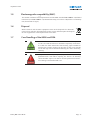 12
12
-
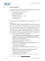 13
13
-
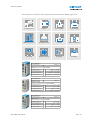 14
14
-
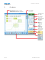 15
15
-
 16
16
-
 17
17
-
 18
18
-
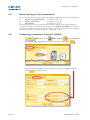 19
19
-
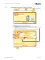 20
20
-
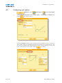 21
21
-
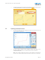 22
22
-
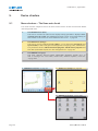 23
23
-
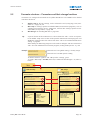 24
24
-
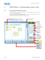 25
25
-
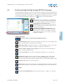 26
26
-
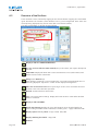 27
27
-
 28
28
-
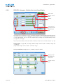 29
29
-
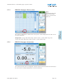 30
30
-
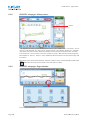 31
31
-
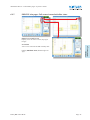 32
32
-
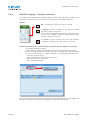 33
33
-
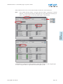 34
34
-
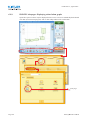 35
35
-
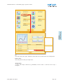 36
36
-
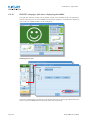 37
37
-
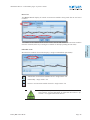 38
38
-
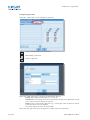 39
39
-
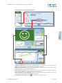 40
40
-
 41
41
-
 42
42
-
 43
43
-
 44
44
-
 45
45
-
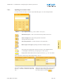 46
46
-
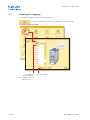 47
47
-
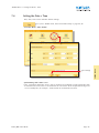 48
48
-
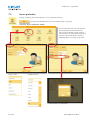 49
49
-
 50
50
-
 51
51
-
 52
52
-
 53
53
-
 54
54
-
 55
55
-
 56
56
-
 57
57
-
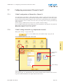 58
58
-
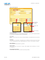 59
59
-
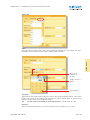 60
60
-
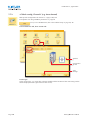 61
61
-
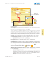 62
62
-
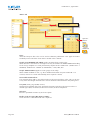 63
63
-
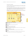 64
64
-
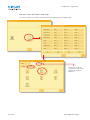 65
65
-
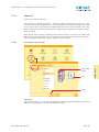 66
66
-
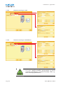 67
67
-
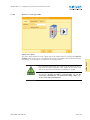 68
68
-
 69
69
-
 70
70
-
 71
71
-
 72
72
-
 73
73
-
 74
74
-
 75
75
-
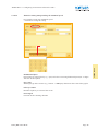 76
76
-
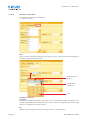 77
77
-
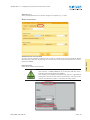 78
78
-
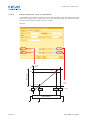 79
79
-
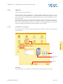 80
80
-
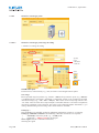 81
81
-
 82
82
-
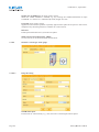 83
83
-
 84
84
-
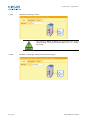 85
85
-
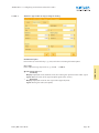 86
86
-
 87
87
-
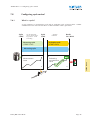 88
88
-
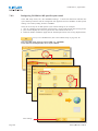 89
89
-
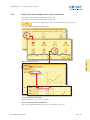 90
90
-
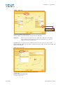 91
91
-
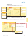 92
92
-
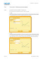 93
93
-
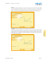 94
94
-
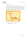 95
95
-
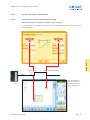 96
96
-
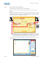 97
97
-
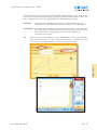 98
98
-
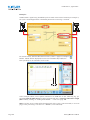 99
99
-
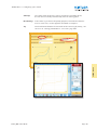 100
100
-
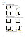 101
101
-
 102
102
-
 103
103
-
 104
104
-
 105
105
-
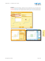 106
106
-
 107
107
-
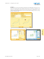 108
108
-
 109
109
-
 110
110
-
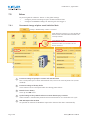 111
111
-
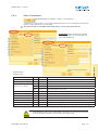 112
112
-
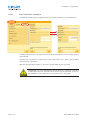 113
113
-
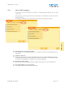 114
114
-
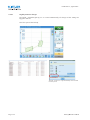 115
115
-
 116
116
-
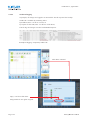 117
117
-
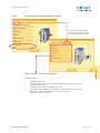 118
118
-
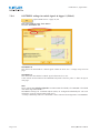 119
119
-
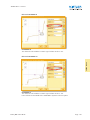 120
120
-
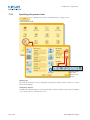 121
121
-
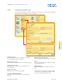 122
122
-
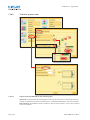 123
123
-
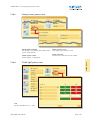 124
124
-
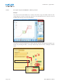 125
125
-
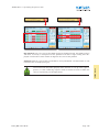 126
126
-
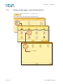 127
127
-
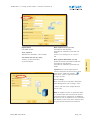 128
128
-
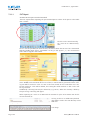 129
129
-
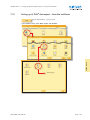 130
130
-
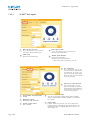 131
131
-
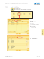 132
132
-
 133
133
-
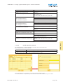 134
134
-
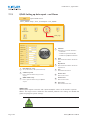 135
135
-
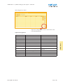 136
136
-
 137
137
-
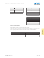 138
138
-
 139
139
-
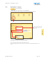 140
140
-
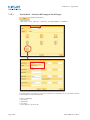 141
141
-
 142
142
-
 143
143
-
 144
144
-
 145
145
-
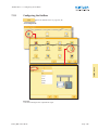 146
146
-
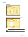 147
147
-
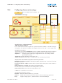 148
148
-
 149
149
-
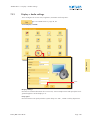 150
150
-
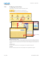 151
151
-
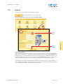 152
152
-
 153
153
-
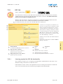 154
154
-
 155
155
-
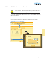 156
156
-
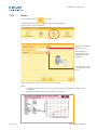 157
157
-
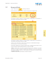 158
158
-
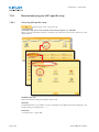 159
159
-
 160
160
-
 161
161
-
 162
162
-
 163
163
-
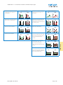 164
164
-
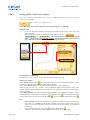 165
165
-
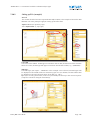 166
166
-
 167
167
-
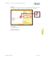 168
168
-
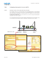 169
169
-
 170
170
-
 171
171
-
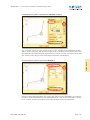 172
172
-
 173
173
-
 174
174
-
 175
175
-
 176
176
-
 177
177
-
 178
178
-
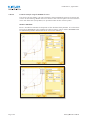 179
179
-
 180
180
-
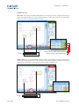 181
181
-
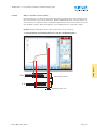 182
182
-
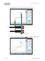 183
183
-
 184
184
-
 185
185
-
 186
186
-
 187
187
-
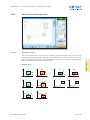 188
188
-
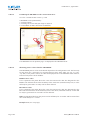 189
189
-
 190
190
-
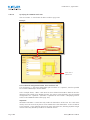 191
191
-
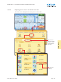 192
192
-
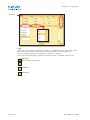 193
193
-
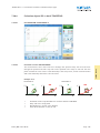 194
194
-
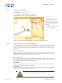 195
195
-
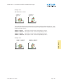 196
196
-
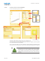 197
197
-
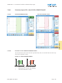 198
198
-
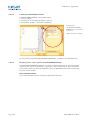 199
199
-
 200
200
-
 201
201
-
 202
202
-
 203
203
-
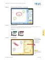 204
204
-
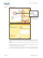 205
205
-
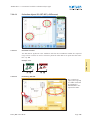 206
206
-
 207
207
-
 208
208
-
 209
209
-
 210
210
-
 211
211
-
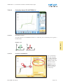 212
212
-
 213
213
-
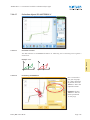 214
214
-
 215
215
-
 216
216
-
 217
217
-
 218
218
-
 219
219
-
 220
220
-
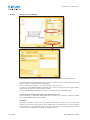 221
221
-
 222
222
-
 223
223
-
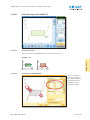 224
224
-
 225
225
-
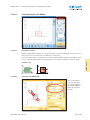 226
226
-
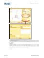 227
227
-
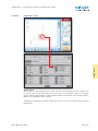 228
228
-
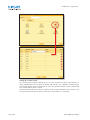 229
229
-
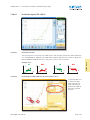 230
230
-
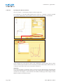 231
231
-
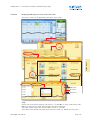 232
232
-
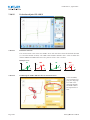 233
233
-
 234
234
-
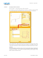 235
235
-
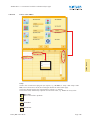 236
236
-
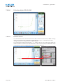 237
237
-
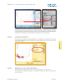 238
238
-
 239
239
-
 240
240
-
 241
241
-
 242
242
-
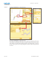 243
243
-
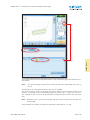 244
244
-
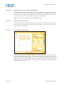 245
245
-
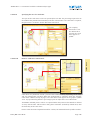 246
246
-
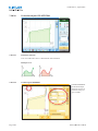 247
247
-
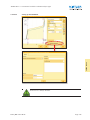 248
248
-
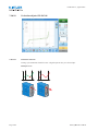 249
249
-
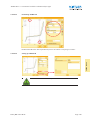 250
250
-
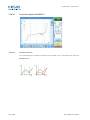 251
251
-
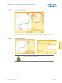 252
252
-
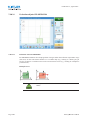 253
253
-
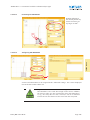 254
254
-
 255
255
-
 256
256
-
 257
257
-
 258
258
-
 259
259
-
 260
260
-
 261
261
-
 262
262
-
 263
263
-
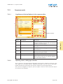 264
264
-
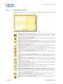 265
265
-
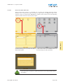 266
266
-
 267
267
-
 268
268
-
 269
269
-
 270
270
-
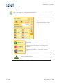 271
271
-
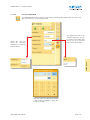 272
272
-
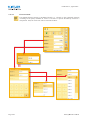 273
273
-
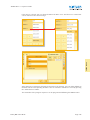 274
274
-
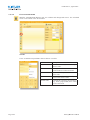 275
275
-
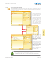 276
276
-
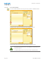 277
277
-
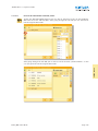 278
278
-
 279
279
-
 280
280
-
 281
281
-
 282
282
-
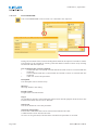 283
283
-
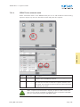 284
284
-
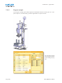 285
285
-
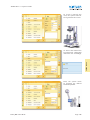 286
286
-
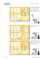 287
287
-
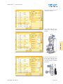 288
288
-
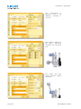 289
289
-
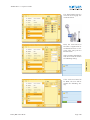 290
290
-
 291
291
-
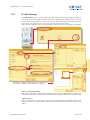 292
292
-
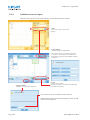 293
293
-
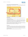 294
294
-
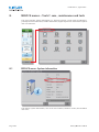 295
295
-
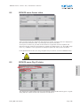 296
296
-
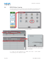 297
297
-
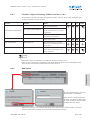 298
298
-
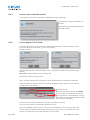 299
299
-
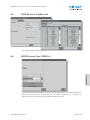 300
300
-
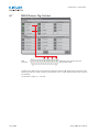 301
301
-
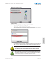 302
302
-
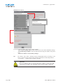 303
303
-
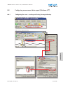 304
304
-
 305
305
-
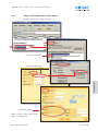 306
306
-
 307
307
-
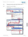 308
308
-
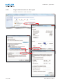 309
309
-
 310
310
-
 311
311
-
 312
312
-
 313
313
-
 314
314
-
 315
315
-
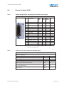 316
316
-
 317
317
-
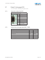 318
318
-
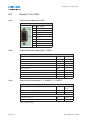 319
319
-
 320
320
-
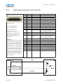 321
321
-
 322
322
-
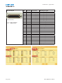 323
323
-
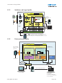 324
324
-
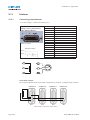 325
325
-
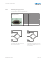 326
326
-
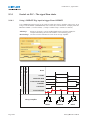 327
327
-
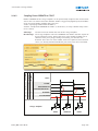 328
328
-
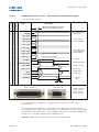 329
329
-
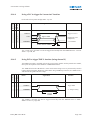 330
330
-
 331
331
-
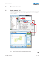 332
332
-
 333
333
-
 334
334
-
 335
335
-
 336
336
-
 337
337
-
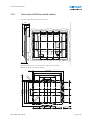 338
338
-
 339
339
-
 340
340
-
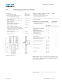 341
341
-
 342
342
-
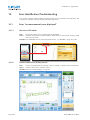 343
343
-
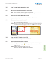 344
344
-
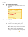 345
345
-
 346
346
-
 347
347
-
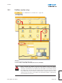 348
348
-
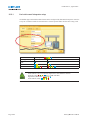 349
349
-
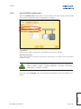 350
350
-
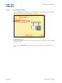 351
351
-
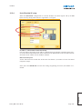 352
352
-
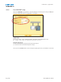 353
353
-
 354
354
-
 355
355
-
 356
356
-
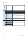 357
357
-
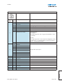 358
358
-
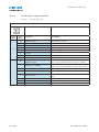 359
359
-
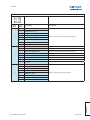 360
360
-
 361
361
-
 362
362
-
 363
363
-
 364
364
-
 365
365
-
 366
366
-
 367
367
-
 368
368
-
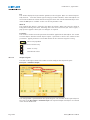 369
369
-
 370
370
-
 371
371
-
 372
372
-
 373
373
-
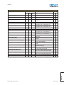 374
374
-
 375
375
-
 376
376
-
 377
377
-
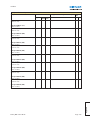 378
378
-
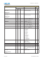 379
379
-
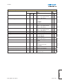 380
380
-
 381
381
-
 382
382
-
 383
383
-
 384
384
-
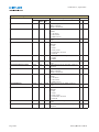 385
385
-
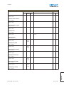 386
386
-
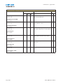 387
387
-
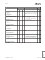 388
388
-
 389
389
-
 390
390
-
 391
391
-
 392
392
-
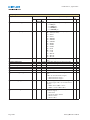 393
393
-
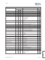 394
394
-
 395
395
-
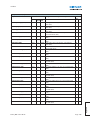 396
396
-
 397
397
-
 398
398
-
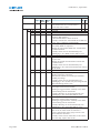 399
399
-
 400
400
-
 401
401
-
 402
402
-
 403
403
-
 404
404
-
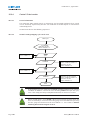 405
405
-
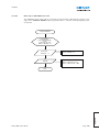 406
406
-
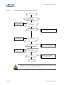 407
407
-
 408
408
-
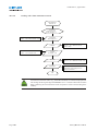 409
409
-
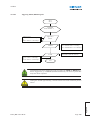 410
410
-
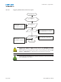 411
411
-
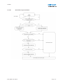 412
412
-
 413
413
-
 414
414
-
 415
415


Kistler 5877B2 Owner's manual
- Type
- Owner's manual
Ask a question and I''ll find the answer in the document
Finding information in a document is now easier with AI
Related papers
-
 Kistler 5867B1000 Owner's manual
-
 Kistler 1200A217A5 Owner's manual
-
 Kistler 5074B212 Owner's manual
-
 Kistler 4021B30HAP1 Quick start guide
-
 Kistler 5080A Owner's manual
-
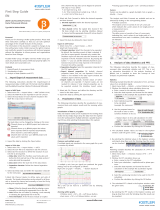 Kistler 2848A Owner's manual
-
 Kistler 5018A0013 Owner's manual
-
 Kistler 9238B10 Owner's manual
-
 Kistler 2829D00 Owner's manual
-
 Kistler 5825A2 Owner's manual


Other documents
-
Burster 9307 Owner's manual
-
-
-
 ETAS ASCMO User guide
-
 ETAS ASCMO-MOCA User guide
-
 ETAS ASCMO User guide
-
 ETAS ASCMO-MOCA User guide
-
-
 Thermo Fisher Scientific Chromeleon 6.60 User manual
-


