Page is loading ...

Copyright © All Rights Reserved. P-MU-ML-360 Published: 2020.04.15
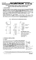
Operating Voltage: 12 or 24 VDC
Voltage Tolerance: ±10%
Current Draw: 280mA/12VDC; 140mA/24VDC
Operating Temperature: -10~45°C
Humidity: 0~95% non-condensing
Solenoid Testing: Tested to over 250,000 cycles
Preload: 500 lbs of pressure strength
Finish: Stainless steel (Surface/Glass mount
Net Weight: ML-350M:673g, ML-360M:1380g
Applicable to horizontal or vertical installations
Locking Mode: Fail-safe locked
Fire Resistance Test Conducted in Accordance
with BSEN 1634-1: 2014 and BSEN 1363-1: 2012
(For ML-350M)
ML-350/360 Series Electric Lock Installation Instructions
Dimensions
ML-350M ML-360M
(30.50mm)
1 3/16”
7 7/8” (200mm)
(45mm)
1 3/4”
5 9/16” (141mm)
7 5/16” (186mm)
7 7/8” (200mm)
(39.5mm)
1 9/16”
(3mm)
1/8”
(25mm)
1”
(25mm)
1”
(3mm)
1/8”
7 5/16” (186mm)
7 7/8” (200mm)
1 1/8” (28mm)
(16.5mm)
5/8”
brackets: Anodized aluminum finish)
ML-350MVGL
2 3/16”
(14mm)
8 3/8” (212mm)
2
1/8”
5 9/16” (142mm)
(56mm)
9/16”
2 3/16”
(56mm)
(53.5mm)
2
1/8”
(53.5mm)

Double Swing
Door
Single Outswing
Door
Single Inswing
Door
When door is closed and locked, the door gap needs to be
less than 5 mm so the auxiliary deadlatch is properly
depressed. Add filler plates to compensate for wide door gaps.
The ML-350/360 series can be installed on
single or double action swing doors.
*5 filler plates
included
Swing Door Application
Filler Plate Installation (For ML-350M)
Copyright © All Rights Reserved. P-MU-ML-360 Published: 2020.04.15
Application
Frame
For wiring access
Door Leaf
25 x 160 x 43mm
20 x 55 x 23mm
6 5/16” (160mm)
(43mm)
1 11/16”
(25mm)
1 3/16”
6 7/8” (175mm)
(23mm)
15/16”
(35mm)
1 3/8”
(43.2mm)
1 11/16”
(20mm)
13/16”
Recommended cutout size in
wood door leaf:
Recommended cutout size in
wood door frame:

Changing the Wire Position (ML-360M)
Change the position of the wires.
Put the cap back in around the
Cap
Cap
Wiring Diagram
Operating
Voltage
Lock Bolt
Sensor Output
Door Status
Output
Lock Sensor Switch:
(Lock status output:1A/125VAC)
N.C.:Unlocked
N.O.:Locked
Door Status Switch:
(Door status output:1A/125VAC)
N.C.:Unlocked
N.O.:Locked
Power
Input
Exit Button
Note: N.O.1 & C.1 negative output
Copyright © All Rights Reserved. P-MU-ML-360 Published: 2020.04.15
Take off the cap and pull
wires for scratch resistance.
out the wires.
Hinge Positions
Left hand shown
Right hand shown
Installation
Glass Mount Installation (ML-350MVGL)
Hinge Positions

Copyright © All Rights Reserved. P-MU-ML-360 Published: 2020.04.15
Do
o
r
F
r
a
m
e
D
oo
r
Fr
a
me
Do
o
r
L
eaf
D
o
or Le
af
D
o
o
rFr
a
me
D
oor
Fram
e
D
o
o
rFr
ame
D
o
o
r
F
r
am
e
Do
o
r
L
eaf
D
oor L
e
af
Door
Frame
D
o
o
rFr
ame
Installation (continued)
Mortise Mounted Horizontal Installation (ML-350M)
Mortise Mounted Vertical Installation (ML-350M)
Surface Mounted Installation (ML-360M)
/