Page is loading ...

3-1
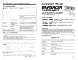
ML-705M Series Electro-Mechanical Lock
Copyright © All Rights Reserved. P-MU-ML-705 Published: 2020.12.07
Unit: mm
Installation Instruction
Dimension
Specification
Packing Contents
Stud Bolt Position
Lock Bolt
Nib
Strike Plate
Australian profile
key cylinder hole
Caution:
Do not completely remove screw 2 (as marked in the figure)
as the interior solenoid might fall off.
Version Changeable:
Take out the Screw 1 , release screw 2 , move the
position and then tighten both screws.
“Fail-Safe”
(Power to Lock)
“Fail-Secure”
(Power to Open)
For fail-safe mode For fail-secure mode
Operating Voltage: 12~24VDC/AC ±10%
Current Draw: 250mA/12VDC; 150mA/24VDC
Operating Temperature: 14°F to 120°F (-10°C~+49°C)
Humidity: 0~85% non-condensing
Version Changeable: Fail-safe or Fail-secure
Lock bolt sensor switch output: SPDT, 3A/125VAC
Latch Throw:16mm
Solenoid testing: Tested to 250,000 cycles
Resistance against door being forced :
1500 lbs (static force); 70 ft-lbs (dynamic force)
Backset: 25mm
25
Backset
21
230
82
49
160.5
250
275
28
100
125
150
2
2
1
2
1
2
1
2
1
2
1
2
1

3-2
Copyright © All Rights Reserved. P-MU-ML-705 Published: 2020.12.07
5 6
7
1 2 3 4
ø5.2
310
275
Installation Instructions
Door Loop
(Optional)
The door loop protects the wiring
from damage at the door hinge.
Attention! Please ensure
that the direction of the
template is correct
Alignment CL
F
r
a
m
e
D
o
o
r
Leaf
Align the center line (CL) of the lock body
lock body CL as closely as possible.
template with the CL of the door leaf. Ensure
the CL of the strike plate template matches the
Cut out mortise holes for the lock body and
strike plate and drill holes according to the
templates.
D
o
o
r
L
e
a
f
D
oo
r
L
e
a
f
Tighten the fixing lugs with screws.
Drill and cut the hole for the lock cylinders
as shown in the template.
F
r
a
m
e
Connect power cable to the lock and test
before screwing to the door leaf.
Install the cylinder
Fix the strike plate.
25
Ø5.2
Ø5.2
25
275
250
150
100
150
Unit:mm
Backset
C
y
l
i
n
d
er
D
oo
r
L
e
a
f
2
5
Backset
D
oo
r
L
e
a
f

3-3
12~24VDC/AC
Copyright © All Rights Reserved. P-MU-ML-705 Published: 2020.12.07
Wiring Diagram
For the 12~24VDC/AC operation only
Red
Red
Varistor
NOTE: The varistor (or diode) must be connected across the terminals as shown above. This protects the
electromechanical lock from spikes and surges.
Butt Splice (IDC) Connector
Using crimper or pliers and pressing the header of
connector down to even position.
(Power input is polarity free)
Yellow
Green
Blue
Access Control
N.C. contact (Fail-safe mode)
N.O. contact (Fail-secure mode)
Lock bolt sensor switch output: SPDT, 3A/125VAC
/