Page is loading ...

Door Handing (LEFT or RIGHT)
Latchbolt Reversal (LEFT or RIGHT)
1) Turn lockcase upside down,reversal plate will drop.
2) Push latchbolt behind forend.
3) Rotate latchbolt 180 degrees to opposite handing.
4) Release latchbolt to extend out from forend.
5) Turn lockcase rightside up.
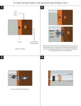
Door Preparation
Fig 1 Fig 2
1) Cut or fold template along dotted line A and align against door edge as in Fig.1 .
2) Mark all hole positions on template on both sides of door.
3) Drill 20mm diameter holes for Lever and/or Cylinder holes as required.
Drill two 9mm diameter holes for bolt through screw fixings.
For Deadlock Functions , do not drill Hole B.
For Plain Latch Function , do not drill Hole C.
For Bathroom Function , drill Holes A & D only.
4) Gently push lock into door mortice.
5) Secure forend with supplied screws as shown in Fig 2.
3800U Series Mortise Locks Installation Instructions
C
B
A
D
A
B
C
D
Interior
Exterior
RIGHT Hand IN
Interior
Exterior
LEFT Hand OUT RIGHT Hand OUT
Exterior
Interior
LEFT Hand IN
Exterior
Interior
Interior
Exterior
RIGHT Hand IN
Interior
Exterior
LEFT Hand OUT RIGHT Hand OUT
Exterior
Interior
LEFT Hand IN
Exterior
Interior
Interior
Exterior
RIGHT Hand IN
Interior
Exterior
LEFT Hand OUT RIGHT Hand OUT
Exterior
Interior
LEFT Hand IN
Exterior
Interior
Interior
Exterior
RIGHT Hand IN
Interior
Exterior
LEFT Hand OUT RIGHT Hand OUT
Exterior
Interior
LEFT Hand IN
Exterior
Interior
5
4
3
2
1
5
4
3
2
1
5
4
3
2
1
2
1
HAGER COMPANIES 139 Victor Street, St. Louis, MO 63104
Ver11MarP1

Installation Instructions for Anti-Panic Functions
Fig 4
Fig 5 Fig 6 Fig 7
1) Using a screw driver,unscrew split follower screws to change handing.
2) Using allen key, secure supplied screw through part I of Split Spindle with part II of Split
Spindle as shown in Fig 4. Ensure that the end of each part of the split spindle is inserted tightly
into the split follower of lockcase.
3) Install the lever handles with through-bolt screws and nuts supplied with levers as shown in Fig 5.
(Lever handles should work independently on each side).
4) Depress the levers as shown in Fig 6. Lever should retract both latchbolt and deadbolt simultaneously
from the direction of escape.
5) Affix outer rose cover of lever handle as shown in Fig 7.
3800U Series Mortise Locks Installation Instructions
Exterior
Interior
Interior
Exterior
Exterior
Interior
Interior
Exterior
Exterior
Interior
Interior
Exterior
Exterior
Interior
Interior
Exterior
Exterior
Interior
Interior
Exterior
1
2
RIGHT Hand IN
LEFT Hand IN
LEFT Hand OUT RIGHT Hand OUT
2
1
1
2
RIGHT Hand IN
LEFT Hand IN
LEFT Hand OUT RIGHT Hand OUT
2
1
1
2
RIGHT Hand IN
LEFT Hand IN
LEFT Hand OUT RIGHT Hand OUT
2
1
1
2
RIGHT Hand IN
LEFT Hand IN
LEFT Hand OUT RIGHT Hand OUT
2
1
HAGER COMPANIES 139 Victor Street, St. Louis, MO 63104
Ver11MarP2

Pre-Installation Instructions
A1
*
and diameter of more than 19mm. Levers should not have sharp edges or sudden change of direction.
* This lock is designed for use on hinged or pivoted door leaves only between temperatures of -20ºC and 80ºC,
for use on single inward or outward opening fire escape route doors.
* Door mass should not exceed 200kg and door size limitations are 2.5m high by 1.3m wide, maximum door distortion
of 5mm allowed, maximum of 1000N has been achieved under abuse test.
* Suitable for use on fire and smoke door asssemblies based on a test in accordance to EN 1634 - 1 grade B.
* 240 Minutes Fire resistance on single or double timber or steel doors. Assessment test nr. 144028 based on fire test
report nr. 145690.
* The safety features of this product are essential to its compliance with EN 179. No modification of any kind, other than
those described in these instructions is permitted.
A2
*
producer for this type of door.
* It is recommended to verify that the door construction allows the use of the device, i.e. to verify that offset hinges and
engaging leaves allow both leaves to be opened simultaneously (See A4), or to verify that the gap between door leaves
does not differ from that defined by the exit device producer, or to verify that the opening elements do not interfere, etc.
A3 Before fitting an emergency exit device to a fire/smoke resisting door, the fire certification of the fire door assembly on
which the exit device has been tested to prove suitability for use on a fire door should be examined. It is of utmost
importance that an exit device is not used on a fire door assembly of a greater fire resistance time than approved for.
A4 Care should be taken to ensure that any seals or weather-stripping fitted to the complete door assembly, do not inhibit
the correct operation of the emergency exit device.
A5 On double doorsets with rebated meeting stiles and where both leaves are fitted with emergency exit devices, it is
essential to check that either leaf will open when its emergency exit device is activated and also that both leaves will
open freely when both emergency exit devices are operated simultaneously.
A6 Where emergency exit devices are manufactured in more than one size, it is important that the correct size is selected.
A7 Category 2 (Standard projection) emergency exit devices should be used in situations where there is restricted width for
escape, or where the doors to be fitted with the emergency exit devices are not able to open beyond 90°
A8 Where an emergency exit device is designed to befitted to a glazed door, it is essential that the glazing is tempered or
laminated glass.
A9 Different fixing can be necessary for fitting emergency exit devices to wood, metal or frameless glass doors. For more
secure fixing, male and female through-door bolts, reinforcement and rivets can be used.
A10 Emergency exit devices are not intended for use on double action (double swing) doors unless specifically designed by
the exit device producer.
A11 The fixing instructions should be carefully followed during installation. These instructions and any maintenance
instructions should be passed on by the installer to the user. See Maintenance Instructions .
A12 The operating element should normally be installed at a height of between 900mm and 1100mm from the finished floor
level, when the door is in the secured position. Where it is known that the majority of the users of the premises will be
young children, consideration should be given to reducing the height of the operating element.
A13 When installing lever operating emergency exit devices, particularly on doors with raised or recessed surfaces,
consideration should be given to minimizing any potential safety risks, such as the trapping of fingers or clothing.
A14 The bolt heads and keepers should be fitted to provide secure engagement. Care should be taken to ensure that no
projection of the bolt heads, when in the withdrawn position, can prevent the door swinging freely.
A15 Where emergency exit devices are to be fitted to double door sets with rebated meeting stiles and self closing devices,
a door coordinator device in accordance with EN 1158 should be fitted to ensure the correct closing sequence of the
doors. This recommendation is particularly important with regard to smoke/fire-resisting door assemblies.
A16 No devices for securing the door in the closed position should be fitted other than specified in this European Standard.
This does not preclude the installation of self-closing devices.
A17 If a door closing device is to be used to return the door to the closed position, care should be taken not to impair the use
of the doorway by the young, elderly and infirm.
3800U Series Mortise Locks Installation Instructions
Before fitting an exit device to a door, the door should be checked to ensure correct hanging and freedom from binding.
It is not recommended, for example, that exit devices be fitted to hollow core doors unless specially designed by the
In compliance to BS EN 179 : 2008 - Emergency Exit Devices, the 3800U-55P series of Anti Panic Escape Locks
are designed to be used in emergency situations where people are familiar with the emergency exit and its hardware
and therefore a panic situtation is most unlikely to develop.
For use with lever handles with safety returns, with length longer than 120mm, projection of between 45 to 100mm
HAGER COMPANIES 139 Victor Street, St. Louis, MO 63104
Ver11MarP3

Pre-Installation Instructions (Cont'd)
A18 Any keepers or protection plates provided should be fitted in order to ensure compliance with this European Standard.
A19 A sign which reads “Rotate handle to open” or “Push to open” as appropriate, or a pictogram should be provided on the
inside face of the door immediately above the operating element or on the operating element if it has a sufficient flat
face to take the size of lettering required.
* For type “B” emergency exit devices intended for use on inwardly opening exit doors, a sign which reads
“Rotate handle and pull to open” or “Pull to open” or a pictogram should be provided on the inside face of the door
immediately above or on pull pad if it has a sufficient flat face to take the size of lettering required.
* The surface area of the pictogram should be not less than 8000mm² and its colours should be white on a green
background. It should be designed such that the arrow points to the operating element, when installed.
* This product has been tested and approved as a set with 19mm return levers and spilt spindles.
Maintenance Instructions
A)
Inspect and operate the emergency exit device to ensure that all components are in a satisfactory working condition.
Using a force gauge, measure and record the operating forces to release the exit device.
B)
Ensure the keeper(s) is (are) free from obstruction.
C) Check that the emergency exit device is lubricated in accordance with the producer’s instructions.
D) Check that no additional locking devices have been added to the door since its original installation.
E) Check periodically that all components of the system are still correct in accordance with the list of approved components
originally supplied with the system.
F) Check periodically that the operating element is correctly tightened and, using a force gauge, measure the operating
forces to release the exit device. Check that the operating forces have not changed significantly from the operating
forces recorded when originally installed.
Hager Companies, Inc.
139 Victor Street
St. Louis, MO 63104
EN 12209 : 2003
European Norm Standard for Mechanically Operated Locks,
Latches & Locking Plates
3800U-55S : 1121 - CPD - AG 0241
Product Classification : 3 X 5 1 0 F 3 B C 2 0
3800U-55F : 1121 - CPD - AG 0242
Product Classification : 3 X 5 1 0 F 3 B C 0 0
3800U-55M : 1121 - CPD - AG 0243
Product Classification : 3 X 5 1 0 F - B 0 2 0
3800U-55L : 1121 - CPD - AG 0244
Product Classification : 3 X 5 1 0 F - B 0 2 0
3800U-55T : 1121 - CPD - AG 0245
Product Classification : 3 X 5 1 0 F 3 B C 2 0
3800U-55B : 1121 - CPD - AG0248
Product Classification : 3 X 5 1 0 F - B G 2 0
Year of Marking : 2010 Certification Body Ref Nr. : 1121
Hager Companies, Inc.
139 Victor Street
St. Louis, MO 63104
BS EN 179 : 2008
European Norm Standard for Emergency Exit Devices
Operated By a Lever or Push Pad
3800U-55P : 1121 - CPD - ABB043 Product Classification : 3 7 6 B 1 3 4 2 A B/D
Year of Marking : 2011 Certification Body Ref Nr. : 1121
Ability to Release : Pass (<=70N unloaded)
Durability of ability to release : Pass (200,000 cycles)
Fire Resistance : C-Self Closing; E-Integrity; I-Insulation Pass (Grade B)
Category of Projection : 2 Field of Door Application : Category B & D
3800U Series Mortise Locks Installation Instructions
HAGER COMPANIES 139 Victor Street, St. Louis, MO 63104
Ver11MarP4
/