Carmanah Technologies Corp. | 250 Bay St, Victoria, BC V9A 3K5, Canada | 1.250.380.0052 | customersupport@carmanah.com | carmanah.com 2
AUDIBLE PUSH BUTTON KIT INSTALL GUIDE
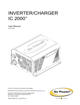
LEVEL 4
Power or Flasher Module Terminal
Function
Campbell
Guardian / Guardian Wave
E F A B C D - E D C B A A B C D E -
PWR
GND
W (Walk)
−GND
- Field
- Field
−GND
W (Walk)
Ensure tactile arrow on button is aligned with crossing
direction.
4. Campbell buttons only: fold and tape (or cut at end of jacket
if permitted by local regulations) unused brown wire at both
end of cable.
5. Connect wires to button terminal as shown in table below.
6. Install button or cover with its supplied hardware, ensuring any gaskets
are in place and cable forms drip loop inside pole.
7. Connect other end of cable to trigger input terminals A through F of
any power or flasher module according to table above.
8. Strain relieve cable per power or flasher module instructions.
NOTE: READ ALL INCLUDED INSTALL GUIDES BEFORE SYSTEM INSTALLATION