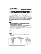
HE120, HE160 HUMIDIFIER INSTALLATION KIT
69-1571 2
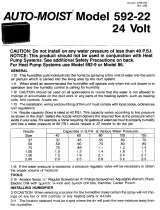
Determining Best Location for Humidifier
• Select a location for the humidifier on the supply
(warm air stream) or the return plenum. See Fig. 1.
• Select a location for the bypass on the opposite
plenum. The humidifier is designed to allow bypass
duct mounting on either side of the humidifier.
• Select a location that cannot damage the air
conditioner A-coil during installation.
• Select a location where the 6 ft (1.86m) of 6 in. (155
mm) duct provided is adequate to connect the
humidifier to the bypass.
— Do not locate the humidifier or bypass on a fur-
nace body.
— Allow adequate clearance in front of and above
the humidifier so you can easily remove the cover
to perform routine maintenance.
— Mount humidifier at least 3 in. (78 mm) above the
furnace body to allow adequate space for the
drain or overflow line.
— Mount humidifier in a conditioned space to pre-
vent freezing.
Fig. 1. Typical humidifier installation locations.
Selecting Water Supply Location
• Use either hard or soft water in the humidifier and
either hot or cold water.
• Make sure that the 20 ft (6.2m) of feed water tubing
provided is adequate to connect the water supply
(saddle valve) with the humidifier float valve.
Locating Closest Floor Drain (If Available)
• Select location with access to a floor drain (if
available); floor drain is optional for safety overflow.
• Make sure that the 10 ft (3.1m) of overflow tubing is
adequate to reach from the humidifier overflow
connection to the floor drain.
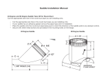
Selecting Location for Humidistat
Select a location for the humidistat on the return plenum
or on the wall in the living space.
NOTE: Mounting on the return plenum is the easiest
installation for the control circuit wiring.
For return duct mounting, the humidistat should be
mounted upstream from the humidifier or bypass so that
it is properly sensing the relative humidity of the living
space. Locate the control at least 8 in. (203 mm)
upstream from the humidifier in the return air duct. (See
Fig 2.)
Fig. 2. Selecting duct location for humidistat.
Locating Closest 120V Electrical Outlet
• Select location with access to an outlet. If not
available, contact an electrician to have one installed.
• Make sure that the 20 ft (6.2m) of thermostat wire is
adequate to reach from the humidifier motor to the
humidistat, to the plug-in transformer in the outlet.
WARNING
Hazardous Voltage.
Can cause personal injury or equipment
damage.
Do not cut or drill into any air conditioning or
electrical accessory.
CAUTION
Sharp Edges Installation Hazard.
Can cause personal injury.
Wear gloves and safety glasses.
1.
Turn off power to the air handing system at the cir-
cuit breaker.
2.
Draw a level line on the plenum in the location
chosen for the humidifier. (Leveling assures opti-
mal humidifier performance.)
3.
Locate the template in the Humidifier Installation
Instructions.
4.
Tape the template in position and trace around the
template.
5.
Remove the template and carefully cut the rectan-
gular opening.
6.
Disassemble the humidifier; remove the cover and
take out the disk or drum assembly. See Fig. 4 or
5.
NOTE: Sidecaps are interchangeable for either left or
right bypass installation. See device installation
instructions.
NOTE: For HE120, go to step 7. For HE160, go to step
13.
M12248C
HORIZONTAL
DOWN
FLO
LOWBOY
HIGHBOY
ALTERNATE LOCATION
RETURN
AIR
RETURN
AIR
6 in. (152 mm)
MINIMUM
15 in. (381 mm)
MINIMUM
BEST
LOCATION
RETURN AIR DUCT
M12831