Page is loading ...

69-2685ES-01
INSTALLATION GUIDE/OWNER’S MANUAL
HE240, HE280
Humidifier and
Installation Kit
M33322
SAVE THIS DOCUMENT
FOR FUTURE REFERENCE
69-2685ES_A.book Page 1 Monday, March 5, 2012 12:04 PM

HE240, HE280 HUMIDIFIER AND INSTALLATION KIT
69-2685ES—01 2
Safety Definitions
These safety terms identify information you must read prior to installing or operating the
humidifier.
WARNING
Indicates a hazardous situation which, if not avoided, could result in death or
serious injury.
CAUTION
Indicates a hazardous situation which, if not avoided, could cause bodily injury or
property damage.
Safety Precautions
Make sure you read and understand the following safety hazards before installing,
using, or working with the humidifier:
WARNING
Serious Personal Injury Hazard.
Can cause electrical shock and injury from moving parts.
Disconnect power and shut off water supply before removing cover.
WARNING
Hazardous Voltage
Can cause personal injury or equipment damage.
Do not cut or drill into any air conditioning or electrical accessory.
CAUTION
Chemical Hazard.
Can cause personal injury or equipment damage.
Do not use any line connected to an air conditioner.
Do not use gas line.
CAUTION
Temperature and Static Pressure Hazard.
Can cause property or equipment damage.
Locate humidifier where ambient temperature is between 32 and 120 °F (0 to 49 °C).
Do not install humidifier where freezing temperatures could occur.
Be sure supply plenum static pressure is no greater than 0.4 in. wc and water pressure is
no greater than 120 psi.
CAUTION
Sharp Edges Installation Hazard.
Can cause personal injury.
Wear gloves and safety glasses.
69-2685ES_A.book Page 2 Monday, March 5, 2012 12:04 PM

HE240, HE280 HUMIDIFIER AND INSTALLATION KIT
3 69-2685ES—01
IMPORTANT
Read and save these instructions.
WELCOME
Congratulations on your purchase of a Honeywell whole-house humidifier. Proper use
of a Honeywell humidifier has numerous benefits related to your family’s health and
comfort, as well as helping to safeguard and protect your home.
How Your Humidifier Works
Your Honeywell humidifier uses the principle that vapor (evaporated water) is created
when warm air blows over a water-soaked area. As the vapor circulates, the relative
humidity rises.
Your humidity control monitors the relative humidity and activates the humidifier
accordingly. The humidifier has a water supply that dispenses water evenly over a
humidifier pad. The warm dry air from the furnace passes over the humidifier pad and
picks up the moist air to circulate it throughout your home.
Humidified air feels warmer and more comfortable so you may be able to lower your
thermostat heating setpoint, which saves money on your heating fuel bills. The end result
is that your humidifier gives you a comfortable environment that is also energy efficient.
Model Specific Features
The HE280 humidifier has water savings technology built in that could save up to 30%
versus leading brands. This translates to up to 20 gallons of water saved per day!
APPLICATION
This kit contains your new Honeywell HE240 or HE280 Humidifier, H8908 Humidistat
and all the accessories required for installation.
69-2685ES_A.book Page 3 Monday, March 5, 2012 12:04 PM

HE240, HE280 HUMIDIFIER AND INSTALLATION KIT
69-2685ES—01 4
PREPARING FOR THE INSTALLATION
Be sure to identify all the required (Table 1) accessories (included) and make sure the
appropriate tools are available before beginning the installation.
Included Accessories
Required Tools
Tools required for installation include:
•Tin snip
• Screwdriver
• Pliers
• Adjustable or open-end wrench
•Drill
•Level
• 3/4 in. (19 mm) sheet metal drill bit
Table 1. Included Accessories.
Quantity Accessory
48 in. (1.22 m)
Bypass ducting including:
6 in. (155 mm) diameter flexible duct
20 ft (6.2 m) 18 gauge, two-strand thermostat wire
20 ft (6.2 m) 1/4 in. (6.35 mm) OD feed water tubing
10 ft (3.1 m) 1/2 in. (12.7 mm) ID drain tubing
1 bag
Connecting and mounting hardware:
4 mounting screws
1 drain tube clamp
1 H8908 Humidistat
1 bag
Saddle Valve Assembly:
1 saddle valve and top clamp
1 threaded bottom clamp
2 bolts
1 rubber gasket
1 brass insert
1 plastic bushing
1 eyelet
1 Plug-in transformer
1 Foil tape roll
1 bag
1 plastic elbow
1 grommet
1 connector strap
1 PVC tubing
1 wire nut
1 Mounting template
69-2685ES_A.book Page 4 Monday, March 5, 2012 12:04 PM

HE240, HE280 HUMIDIFIER AND INSTALLATION KIT
5 69-2685ES—01
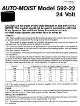
Determining Best Location for Humidifier
• Select a location for the humidifier on the supply (warm air stream) duct. See Fig. 1
for examples. Return duct mounting is acceptable if there are space restrictions on
the supply duct. If you are mounting the humidifier on the return duct, simply swap
“return duct” for “supply duct” throughout these instructions.
• Select a location that cannot damage the air conditioner A-coil during installation.
• Do not locate the humidifier on the furnace body.
• Mount the humidifier in a conditioned space to prevent freezing.
• Mount the humidifier at least 3 in. (78 mm) above the furnace body to allow
adequate space for the solenoid valve and drain line.
Fig. 1. Typical humidifier installation locations.
M12248D
HORIZONTAL
DOWN
FLO
LOWBOY
HIGHBOY
HUMIDIFIER
BYPASS
COLLAR
69-2685ES_A.book Page 5 Monday, March 5, 2012 12:04 PM

HE240, HE280 HUMIDIFIER AND INSTALLATION KIT
69-2685ES—01 6
Fig. 2. Typical humidifier installation locations.
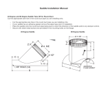
Selecting Location for Humidistat
• Select a location for the humidistat on the return plenum or on the wall in the living space.
• Mounting on the return plenum is the easiest installation for the control wiring circuit.
IMPORTANT
The humidistat must be mounted upstream from the humidifier or bypass duct to ensure
it is properly sensing the relative humidity of the living space. Locate the control at least
8 in. (203 mm) upstream from the humidifier in the return air duct. (See Fig. 3.)
Fig. 3. Selecting duct location for humidistat.
Locating Closest 120 V Electrical Outlet
• Select location with access to an outlet. If not available, contact an electrician to
have one installed.
• Make sure that the 20 ft (6.2 m) of thermostat wire is adequate to reach from the
humidifier to the humidistat, and also from the humidifier to the transformer. Please
note that the thermostat wire will need to be cut into the 2 correct lengths. See
“Wiring” on page 14 for more information.
CHOOSE A LOCATION IN A CONDITIONED
SPACE THAT HAS ACCESS TO A WATER SUPPLY
PIPE. COLD OR HOT WATER CAN BE USED.
SELECT A SURFACE ON THE HVAC SUPPLY OR
RETURN DUCT WITH CLEARANCE FOR THE
SOLENOID VALVE, DRAIN LINE AND COVER
REMOVAL.
LOCATION MUST ALSO HAVE ACCESS TO 120
VAC POWER.
ENSURE THE LOCATION IS NEAR A DRAIN.
CONSULT LOCAL PLUMBING CODES FOR
PROPER DRAINAGE.
M33410
ALTERNATE LOCATION
RETURN
AIR
RETURN
AIR
6 in. (152 mm)
MINIMUM
15 in. (381 mm)
MINIMUM
BEST
LOCATION
RETURN AIR DUCT
M12831
69-2685ES_A.book Page 6 Monday, March 5, 2012 12:04 PM

HE240, HE280 HUMIDIFIER AND INSTALLATION KIT
7 69-2685ES—01
INSTALLATION
1. Turn off power to the air handling system at the circuit breaker.
2. Draw a level line on the plenum in the selected location.
IMPORTANT
To ensure optimal product performance, be sure the mounting template is
level before marking. Use of a small level is recommended.
3. Locate the template (form number 69-2710 included in the box). For the HE240
model, cut out the template along the dotted line.
4. Tape the template in position and trace around the template.
5. Remove the template and carefully cut the rectangular opening using tin snips.
6. Disassemble the humidifier; remove the cover and take out the humidifier pad
assembly. See Fig. 4.
Fig. 4. Disassembling humidifier.
M33323
WATER
FEED NOZZLE
FRAME
HUMIDIFIER
HOUSING
WATER
FEED TUBE
HUMIDIFIER
PAD ASSEMBLY
COVER
SIDEWALL
BY-PASS SIDEWALL
PRESSURE SWITCH
SOLENOID VALVE
PerfectFLO™ WATER
DISTRIBUTION TRAY
69-2685ES_A.book Page 7 Monday, March 5, 2012 12:04 PM

HE240, HE280 HUMIDIFIER AND INSTALLATION KIT
69-2685ES—01 8
7. Make sure the humidifier housing is
level, then position it in the opening
so the plastic tabs are in place on the
lower sheet metal edge of the open-
ing. Use pliers, as necessary, to flat-
ten cut edges. See Fig. 5.
8. Secure the humidifier housing to the
opening at the top and bottom using
sheet metal screws.
9. Use the 6 in. (155 mm) starter collar
as a template to mark the opening for
the bypass. The starter collar end
can be identified by the pliable metal
tabs.
Fig. 5. Installing humidifier on duct.
10. Carefully cut the opening for the 6 in. (155 mm) starter collar end of the 48 in.
(1.22 m) flex duct. See Fig. 6. Use a drill to start the cut in the middle of the cir-
cle. Cut in an outward spiral to assist in controlling the cut.
Fig. 6. Cutting bypass opening.
DUCT
LEVEL
SHEET METAL
SCREWS (4)
PLASTIC
TABS (2)
DRAIN TUBING
M33324
OPENING
TO AIR DUCT
STARTING
HOLE
6 IN. ROUND TEMPLATE
M20172
69-2685ES_A.book Page 8 Monday, March 5, 2012 12:04 PM

HE240, HE280 HUMIDIFIER AND INSTALLATION KIT
9 69-2685ES—01
11. Reassemble humidifier side plates to customize the orientation for your specific
install. The side plate with the humidifier port needs to be on the side of the
humidifier that is closest to the 6 in. (155mm) hole cut in Step 10.
12. Insert flex duct with starter collar into the 6" (155mm) hole that was cut in Step
10. Reach into hole THROUGH THE FLEX DUCT so that the pliable metal tabs
can be bent outwards into the hole. These tabs, when bent outwards, will help
secure the flex duct into your home's duct work.
13. Slide remaining loose end of flex duct over the humidifier port on the HE240/
HE280, making sure that the flex duct advances past the raised plastic tabs on
the port. These tabs will help to hold the flex duct in place. Verify that the damper
blade has adequate clearance to move back and forth between the summer and
winter positions. Secure the flex duct in place with the plastic connector strap.
14. Seal the duct connec-
tions with foil tape.
Seal both
1) the connection
between the starter
collar end of the flex
duct and the home's
duct work and
2) the end of the flex
duct to the humidifier
over the top of the
connector strap.
15. Reinstall the humidi-
fier pad assembly in
the humidifier hous-
ing.
16. Hinge the cover in
place and secure with
the thumbscrew
located at the bottom
of the cover.
Fig. 7. Connecting bypass ducting.
M33325
HUMIDIFIER PORT
CONNECTOR STRAP
69-2685ES_A.book Page 9 Monday, March 5, 2012 12:04 PM

HE240, HE280 HUMIDIFIER AND INSTALLATION KIT
69-2685ES—01 10
Connecting the Plumbing
Use hot or cold water and either hard or softened water in the humidifier.
NOTE: Using hot water will increase operating costs, but may provide a small
increase in the amount of humidity delivered.
IMPORTANT
Please consult local plumbing code for proper plumbing regulations before begin-
ning. Use of a manual shutoff valve may be required to meet code in your area.
1. Shut off the water.
2. Use the self-piercing saddle valve (included)
to tap into the water supply line at the loca-
tion selected. Turn the handle on the top of
the saddle valve to the right (clockwise) until
the needle pierces the water supply line.
Leave the needle in this position until the
humidifier is fully installed to prevent leaking
(even though the water supply is turned off,
there can still be water in the line that will
leak as soon as the needle is backed out).
See Fig. 8. If tapping into galvanized pipe,
drain the line and pre-drill 3/16 in. tap for the
saddle valve.
Fig. 8. Installing the saddle valve.
NOTE: The saddle valve is not designed to regulate water flow. The valve is
either open or closed.
IMPORTANT
To prevent debris from clogging the solenoid in-line filter, be sure to install the
saddle valve handle pointing toward the ceiling.
3. Use 1/4 in. (6 mm) OD tubing and
connect the saddle valve to the
inlet side of the solenoid valve on
the humidifier (see Fig. 9).
a. Place the brass compression nut
over the tubing.
b. Slide the plastic compression ring
over the tubing. (Discard copper
compression ring provided with
valve.)
c. Install brass insert into end of
tubing.
Fig. 9. Installing feed tubing.
NOTE: To prevent leaking, use plastic (Delrin) compression rings with plastic
tubing. Use copper sleeve rings only with copper tubing.
M20175
SCREW DRIVER
WATER LINE
M33404
BRASS COMPRESSION NUT
PLASTIC
COMPRESSION
RING
BRASS INSERT
69-2685ES_A.book Page 10 Monday, March 5, 2012 12:04 PM

HE240, HE280 HUMIDIFIER AND INSTALLATION KIT
11 69-2685ES—01
d. Insert the tubing into the saddle valve fitting and support the valve while
tightening the compression nut.
e. Insert plastic supply tubing into quick connect fitting. Insert fully, and apply
modest pull pressure to ensure a tight fit.
4. Use the following steps to install a
1/2 in. (13 mm) drain tube between the
humidifier and the floor drain (see Fig. 10).
a. Slide the drain clamp over the tubing.
b. Push the tubing over the drain nipple
on the humidifier.
c. Hand-tighten the clamp around the
tubing to secure it to the humidifier
drain. The clamp is tightened by com-
pressing the two sides together so
that one side fits into the ridged grove
on the other side.
d. Secure the tubing (can use foil tape)
along the route to prevent movement
and ensure downward slope for cor-
rect drainage.
Fig. 10. Installing the drain tubing.
NOTE: Cut tubing to correct length so the tubing terminates at the drain.
Connecting the Pressure Switch
1. If the humidifier is installed on
the supply duct (as is recom-
mended), the pressure switch
needs to have the tubing fed to
the return duct. If the humidifier
is installed on the return duct,
the pressure switch needs to
have the tubing fed to the supply
duct.
2. Drill a 3/4-in. (19 mm) diameter
hole in the duct within 10 ft.
(3 m) of the switch to ensure the
provided tubing reaches the
pressure tap elbow.
Fig. 11. Pressure switch.
M20177
M33405
69-2685ES_A.book Page 11 Monday, March 5, 2012 12:04 PM

HE240, HE280 HUMIDIFIER AND INSTALLATION KIT
69-2685ES—01 12
3. Insert the black rubber grommet into
the duct hole.
4. Connect the tubing to the tubing fit-
ting elbow and insert the tubing fit-
ting elbow into the black rubber
grommet.
5. Connect the other end of the tubing
to the applicable pressure connec-
tion on the switch.
a. If the humidifier is installed on the
supply duct (as is recom-
mended), the tube that inserts
into the humidifier needs to be
attached to the black port, and
the tube that runs to the return
duct needs to be attached to the
gray port.
b. If the humidifier is installed on the
return duct, the tube that inserts
into the humidifier needs to be
attached to the gray port, and the
tube that runs to the supply duct
needs to be attached to the black
port.
Fig. 12. Installing the pressure switch
tubing.
6. You may cut the tubing to fit the connection length between the elbow fitting and
switch. It is also recommended to secure the hose to existing structures to avoid
accidental disconnection.
M33326
69-2685ES_A.book Page 12 Monday, March 5, 2012 12:04 PM

HE240, HE280 HUMIDIFIER AND INSTALLATION KIT
13 69-2685ES—01
Installing the Humidistat
1. Find the mounting template included in the H8908 Humidistat Installation
Instructions.
2. Apply the template to the return
duct (see Fig. 3 on page 6). Make
sure the template is level before
drilling. (Use of a small level is rec-
ommended.)
3.
Remove base bracket from the H8908
.
4. Slide the foam gasket onto the base.
(See Fig. 14.)
5. Position the base bracket on the duct
with the arrow up.
6. Secure the base bracket to the duct
using the four 1 in. (25 mm) mounting
screws provided with the humidistat.
(See Fig. 15.)
Fig. 13. Humidistat base and rear view.
7. Connect the low-voltage wires to the leads and replace the H8908 case.
See Fig. 16.
NOTE: For wall mounting instructions, see the H8908 Installation Instructions.
Fig. 14. Slide the foam
gasket onto the base.
Fig. 15. Secure the
base bracket to the duct.
M20179
WIRE SLOT
HUMIDISTAT WIRES
HUMIDISTAT BASE REAR OF HUMIDISTAT
M24733
M29879
69-2685ES_A.book Page 13 Monday, March 5, 2012 12:04 PM

HE240, HE280 HUMIDIFIER AND INSTALLATION KIT
69-2685ES—01 14
WIRING
CAUTION
Hazardous Voltage.
Can cause personal injury or equipment damage.
Disconnect power supply before installing or servicing equipment.
IMPORTANT
All wiring must comply with applicable local code, ordinances and regulations.
Wire the humidifier solenoid valve, humidistat and transformer. See Fig. 16.
Fig. 16. Wiring the controls and the HE240.
Fig. 17. Wiring the controls and the HE280.
1. Determine the length of wire necessary to run from the humidifier to the humidi-
stat. Cut to length and strip the ends appropriately.
2. Connect the red and white wires to the leads on the humidistat per the wiring
diagram. Use the provided wire nuts to secure the connections.
3. Taking the opposite end of the wire, connect RED WIRE to one terminal on the
humidifier. Leave the white wire loose at this point.
4. Using remaining wire, determine length needed to run from humidifier to the
transformer. Cut to length and strip the ends appropriately.
5. Unplug the transformer. Connect the red and white wires to the transformer by
loosening the screws on the transformer, wrap wire around screw post and then
re-tighten the screws.
6. Taking the opposite end of the wire, connect the RED WIRE to the open remain-
ing loose terminal on the humidifier.
7. Connect the remaining two white wires together using the provided wire nut.
M33413
HUMIDIFIER
SOLENOID
VALVE
H
u
m
i
d
i
t
y
Co
n
t
r
o
l
égu
la
t
e
u
r
d
'
h
u
m
i
d
i
t
é
-
2
0
¡
F
-
1
0
¡
F
0
¡
F
+
1
0
¡F
+2
0
¡F
O
ve
r
2
0
¡
F
1
5
%
2
0
%
2
5
%
30
%
3
5
%
4
0%
H
U
M
ID
I
T
Y
S
E
T
T
I
N
G
O
U
TD
O
O
R
TE
M
P
ER
ATU
R
E
-
3
0 ¡
C
-
25
¡
C
-
2
0
¡
C
-
1
0
¡C
-
5
¡C
O
ve
r
0
¡
C
HUMIDISTAT
TRANSFORMER
WHITE WIRE
RED WIRE
WIRE NUT
WHITE WIRE
WHITE WIRE
WIRE NUTWIRE NUT
RED
WIRE
RED
WIRE
RED WIRE
WHITE WIRE
1
2
5
4
7
6
3
M33327
HUMIDIFIER
SOLENOID
VALVE
H
u
m
id
i
t
y
Co
n
t
r
o
l
é
gu
la
t
e
u
r
d
'h
u
m
i
d
i
t
é
-
2
0
¡F
-
1
0
¡
F
0
¡
F
+
1
0
¡
F
+
2
0
¡F
O
ve
r
2
0
¡F
1
5
%
2
0
%
2
5
%
3
0
%
3
5
%
4
0%
H
U
M
I
D
IT
Y
S
E
T
T
I
N
G
OU
T
D
O
O
R
TE
M
P
ER
ATU
R
E
-
3
0
¡
C
-
2
5
¡
C
-
2
0
¡
C
-
1
0
¡C
-
5
¡C
O
ver
0
¡
C
HUMIDISTAT
TRANSFORMER
WHITE WIRE
RED WIRE
WIRE NUT
WHITE WIRE
WHITE WIRE
WIRE NUT
WIRE NUT
RED WIRE
RED
WIRE
RED WIRE
WHITE WIRE
69-2685ES_A.book Page 14 Monday, March 5, 2012 12:04 PM

HE240, HE280 HUMIDIFIER AND INSTALLATION KIT
15 69-2685ES—01
TESTING HUMIDIFIER OPERATION
Checklist
Humidifier is level.
Control wiring was reviewed using circuit diagram.
Humidifier is plugged in.
Feed line has no kinks.
Drain line slopes continuously down and ends at floor drain.
Water hose inside humidifier is connected to PerfectFLO
™
water distribution tray.
Tubing from pressure switch is not kinked or pinched.
After installation use the following steps to check the humidifier operation:
1. Turn on the power and the water supply
2. Ensure the saddle valve is fully opened by turning the handle to the left (counter
clockwise) until there is resistance.
3. Turn the H8908 Humidistat to On and turn on the heat by setting the thermostat
to 10 ºF (6 ºC) above room temperature.
IMPORTANT
The furnace blower must be on to activate the humidifier.
4. Make sure that water is flowing out of the drain hose. If water does not flow, see
Troubleshooting Your Humidifier section.
5. Check for leaks.
6. Reset the thermostat and H8908 Humidistat to a comfortable setting for auto-
matic operation. (35% relative humidity is recommended.)
OPERATION
Controlling Your Humidity Settings
Your H8908 Humidistat controls your humidifier.
• Choose the humidity control setting using the combination of relative humidity/
outdoor temperature setting scale on your humidity control dial.
• Match the dial setting to the outdoor temperature to optimize the humidity level
while reducing the moisture condensation on your windows. See Table 2 on
page 16 to adjust the humidity control to the recommended setting.
NOTE: As the outside temperature drops, a lower humidity setting is recom-
mended to accommodate dewpoint effects. These settings should
reduce the accumulation of moisture and ice on windows and other
areas of the home.
• Adjust the humidity control setting to adjust for indoor activities such as cooking,
showering and clothes drying, which can cause excessive levels of humidity that
can accumulate moisture on your windows.
NOTE: If these activities persist for more than a few hours, set the humidity
control to the lowest setting to turn off the humidifier. If the condition
does not improve, ventilate your home to remove the moisture.
69-2685ES_A.book Page 15 Monday, March 5, 2012 12:04 PM

HE240, HE280 HUMIDIFIER AND INSTALLATION KIT
69-2685ES—01 16
MAINTAINING YOUR HUMIDIFIER
A regular maintenance program prolongs the life of your humidifier and makes your
home more comfortable. The frequency of cleaning depends on the condition of your
water.
You can use either hard or soft water in your humidifier, but hard water mineral
deposits are more difficult to clean than soft water deposits.
Use the following procedure to clean your Honeywell humidifier.
IMPORTANT
Never oil any part of the humidifier.
Once per year, depending on water quality
(either at the beginning or the end of the humidification season)
1. Disconnect the power by unplugging the transformer from the outlet and turn off
the humidifier’s water supply by turning the handle to the right (clockwise) until
the water stops flowing and/or there is resistance.
2. Remove the humidifier cover. See Fig. 18 on page 17.
3. Remove the humidifier pad assembly from the humidifier by grasping the top of
the tray and pulling it toward you.
4. Pull one side of the humidifier pad assembly frame toward you and remove the
tray from the frame.
5. Gently pinch the water nozzle prongs (a pair of prongs is located on each side of
the PerfectFLO
™
water distribution tray) inward until you can lift the water nozzle
off the tray.
6. Slide the humidifier pad out of the frame and discard the pad. Honeywell recom-
mends replacing the humidifier pad on an annual basis. However, if your home
has hard water, the pad may need to be replaced more frequently.
7. Carefully remove any mineral deposits from the tray and frame. Be sure the
frame drain hole has nothing blocking it.
8. Disconnect the drain hose from the drain fitting on the bottom of the humidifier
housing.
Table 2. Setting Your Humidistat.
When Outside
Temperature is:
Use This Control
Setting:
-20 °F (-29 °C) 15
-10 °F (-23 °C) 20
0 °F (-18 °C) 25
+10 °F (-12 °C) 30
+20 °F (-7 °C) 35
Above 20 °F (-7 °C) 40
69-2685ES_A.book Page 16 Monday, March 5, 2012 12:04 PM

HE240, HE280 HUMIDIFIER AND INSTALLATION KIT
17 69-2685ES—01
9. Clean the drain fitting, if neces-
sary.
10. Bend the drain hose to loosen
any mineral deposits.
11. Flush the drain hose with pres-
surized water (a running tap)
to clean the hose.
12. Reattach the drain hose to the
drain fitting.
13. Slide a new Honeywell humidi-
fier pad back into the frame.
14. Snap the water nozzle back on
the tray.
15. Reattach the tray to the frame.
16. Place the humidifier pad
assembly in the humidifier
housing and press until the
assembly is completely
seated. Be careful not to pinch
or kink the water feed tube.
17. Replace the humidifier cover.
18. Verify the humidifier operation
by following the steps in the
Checking Your Humidifier for
Correct Operation section.
Fig. 18. Cleaning your humidifier.
End of Humidification Season
• Clean the humidifier and shut it off at the end of the heating season.
• Turn the water off at the saddle valve by turning the handle to the right (clockwise)
until the water stops flowing and/or there is resistance.
• Unplug the humidifier at the wall outlet
• Turn the damper blade to the "summer" position.
IMPORTANT
Be sure the humidifier power is off.
Replacement Humidifier Pads
Honeywell recommends replacing the humidifier pad on an annual basis. However, if
your home has hard water, the pad may need to be replaced more frequently because
of the buildup of minerals diminishing its ability to operate normally. If there is access to
a water softener, it is recommended to use softened water.
Table 3. Replacement pad part numbers.
Humidifier Model Replacement Pad
HE240 HC22P
HE280 HC26P
M33328
PerfectFLO™ WATER
DISTRIBUTION TRAY
HUMIDIFIER PAD ASSEMBLY
WATER FEED NOZZLE
HUMIDIFIER HOUSING
SIDEWALL
BYPASS
SIDEWALL
COVER
WATER FEED TUBE
69-2685ES_A.book Page 17 Monday, March 5, 2012 12:04 PM

HE240, HE280 HUMIDIFIER AND INSTALLATION KIT
69-2685ES—01 18
Vacation
• When leaving on vacation, turn off the humidifier water supply and your humidistat.
• When you return, turn on the humidifier water supply and reset your humidistat.
Start of the Humidification Season
Use the following steps to bring the humidifier back to normal (winter) operation:
1. Turn damper blade to "winter" position.
2. Plug the humidifier transformer back into wall outlet and turn water supply to the
humidifier back on by turning the handle on the saddle valve to the left (counter
clockwise) until there is resistance.
3. Turn the humidistat to its highest setting and set the thermostat to 10 °F (6 °C)
above the room temperature.
4. Observe that water is flowing out of the drain hose.
NOTE: The furnace blower must be running to activate the humidifier.
5. Reset the thermostat and humidistat to a comfortable setting for automatic oper-
ation. (35% relative humidity is recommended.)
TROUBLESHOOTING YOUR HUMIDIFIER
Table 4. Troubleshooting Humidifier.
Problem What to look for What to do
Water
leakage
Leaking joints. Shut off water and tighten connections.
Brass tubing inserts Verify that brass tubing inserts are used.
Saddle valve leaking. Verify rubber pad is installed on saddle valve.
No water to
drain.
Electrical Verify control circuit wiring.
Check all connections.
Humidistat Turn humidistat up and down and listen for
contact to click.
Humidifier power Verify that outlet has power.
Solenoid After verifying other wiring components, turn on
furnace fan, turn humidistat up and down, and
listen for solenoid to click.
Plumbing Verify plumbing connections.
Check for kinks.
Saddle valve Verify that needle pierces water line and then
backs out needle to open valve.
Humidifier Remove cover and verify that water flows into
distribution tray.
Drain tubing Verify no obstructions.
Air leakage Check duct joints Seal with foil tape.
69-2685ES_A.book Page 18 Monday, March 5, 2012 12:04 PM

HE240, HE280 HUMIDIFIER AND INSTALLATION KIT
19 69-2685ES—01
Low
humidity
Furnace blower
not operating.
• Reset circuit breaker or check for blown fuse.
• Check that the furnace power is on.
• Check all external wiring connections.
• Check the humidity control setting.
• Verify that pressure switch tubing isn't
pinched or obstructed.
• Call a professional heating contractor.
Rapid air changes.
Drafts (cold air is
dry and is an
added load to the
humidifier).
• Keep doors and windows closed.
• Close fireplace damper when not in use.
• Keep exhaust fan running time to a minimum.
• Seal around doors and windows.
Damper in
“summer” position
• Set damper blade to "winter" position to allow
humidification.
High
humidity
Condensation on
walls.
• Turn off humidity control and water until
condensation is completely evaporated.
Heavy
condensation on
windows.
• Turn humidity control down low enough to
eliminate condensation caused by moisture
from bathing, mopping, cooking, etc. If
moisture persists, more ventilation is needed.
Table 4. Troubleshooting Humidifier. (Continued)
69-2685ES_A.book Page 19 Monday, March 5, 2012 12:04 PM

HE240, HE280 HUMIDIFIER AND INSTALLATION KIT
Automation and Control Solutions
Honeywell International Inc.
1985 Douglas Drive North
Golden Valley, MN 55422
customer.honeywell.com
® U.S. Registered Trademark
© 2012 Honeywell International Inc.
69-2685ES—01 M.S. 03-12
Printed in United States
LIMITED ONE-YEAR WARRANTY
Honeywell warrants this product, excluding humidifier pad, to be free from defects in the workmanship or
materials, under normal use and service, for a period of one (1) year from the date of purchase by the
consumer. If, at any time during the warranty period, the product is defective or malfunctions, Honeywell shall
repair or replace it (at Honeywell’s option) within a reasonable period of time.
If the product is defective, return it, with a bill of sale or other dated proof of purchase, to the retailer where you
purchased it.
This warranty does not cover removal or reinstallation costs. This warranty shall not apply if it is shown by
Honeywell that the defect or malfunction was caused by damage which occurred while the product was in
the possession of a consumer.
Honeywell’s sole responsibility shall be to repair or replace the product within the terms stated above.
HONEYWELL SHALL NOT BE LIABLE FOR ANY LOSS OR DAMAGE OF ANY KIND, INCLUDING ANY
INCIDENTAL OR CONSEQUENTIAL DAMAGES RESULTING, DIRECTLY OR INDIRECTLY, FROM ANY
BREACH OF ANY WARRANTY, EXPRESS OR IMPLIED, OR ANY OTHER FAILURE OF THIS PRODUCT.
Some states do not allow the exclusion or limitation of incidental or consequential damages, so this limitation
may not apply to you.
THIS WARRANTY IS THE ONLY EXPRESS WARRANTY HONEYWELL MAKES ON THIS PRODUCT. THE
DURATION OF ANY IMPLIED WARRANTIES, INCLUDING THE WARRANTIES OF MERCHANTABILITY
AND FITNESS FOR A PARTICULAR PURPOSE, IS HEREBY LIMITED TO THE ONE YEAR DURATION
OF THIS WARRANTY. Some states do not allow limitations on how long an implied warranty lasts, so the
above limitation may not apply to you.
This warranty gives you specific legal rights, and you may have other rights which vary from state to state.
If you have any questions concerning this warranty, please write to Honeywell Customer Care, 1985 Douglas
Drive, Minneapolis, MN55422.
69-2685ES_A.book Page 20 Monday, March 5, 2012 12:04 PM
/