Honeywell HE120 User manual

Type
User manual

This manual is also suitable for

INSTALLATION INSTRUCTIONS
69-1860EF-01
HE120 By-pass Drum Humidifier
Contents
Unpacking the Unit .................................................................................................................................................................... 2
Before You Begin ...................................................................................................................................................................... 4
STEP 1: Determine Best Location ............................................................................................................................................. 4
STEP 2: Install Humidifier ......................................................................................................................................................... 5
STEP 3: Install Bypass Collar .................................................................................................................................................. 7
STEP 4: Install Bypass Duct ..................................................................................................................................................... 9
STEP 5: Assemble Humidifier Drum ......................................................................................................................................... 10
STEP 6: Assemble Humidifier ................................................................................................................................................... 11
STEP 7: Install Drain ................................................................................................................................................................. 13
STEP 8: Install Saddle Valve ..................................................................................................................................................... 13
STEP 9: Install Water Line ........................................................................................................................................................ 15
STEP 10: Install Humidistat ....................................................................................................................................................... 16
STEP 11: Wiring ........................................................................................................................................................................ 19
STEP 12: Testing and Checkout ............................................................................................................................................... 20
HE120 BY-PASS DRUM HUMIDIFIER
69-1860EF—01 2
UNPACKING THE UNIT
This box contains all of the parts necessary to install your new Honeywell HE120 Humidifier in most installations. Before
continuing, please take the time to familiarize yourself with these components.
Humidifier Housing
Float Valve
(Installed on
Humidifier
Housing)
Humidifier Cover
Water Pan
Humidifier Pad
Motor Cover
Motor Plate
Humidistat
Humidifier Accessory Bag (Plastic Bag)
A Bearing Bracket
B Valve Hole Plug
C Drain Fitting
D Drum Shaft
E Spring Retainer (x2)
F Humidistat Label
G Humidistat Template
H Brass Compression Nut
I Brass Compression Sleeve
J Humidistat Gasket
Humidistat Installation Kit (Small Bag inside
Humidifier Accessory Bag)
K Screw Terminals (x2)
L #6 x 1 in. Sheet Metal Screw (x4)
HE120 BY-PASS DRUM HUMIDIFIER
3 69-1860EF—01
Tools
You will need the following tools to complete the installation:
Tin snips
Screwdriver
Adjustable wrench or 1/2 in. open-end wrench
Drill
Drill bits
Level
Marker
Wire stripper
Utility knife
Scissors
Closed Drum End
Open Drum End
Bypass Duct
(6 in. dia.
Flexible)
Bypass Collar
Damper
Saddle Valve Kit (Small Plastic Bag)
M Saddle Valve
N BracketO
P #10 x 1-3/4 in. Machine Screws (x 2)
Q Brass Compression Nut
R Brass Insert
S Plastic Compression Sleeve
T Brass Compression Sleeve
U 18-gauge two-strand thermostat wire (20 ft.)
V 1/4 in. plastic water tubing (20 ft.)
W 3/8 in. inside diameter, 1/2 in. outside diameter
plastic Overflow Tube (10 ft.) [Not Included]
X Plug-in Transformer
Y Duct Tape (10 yds.)
Installation Accessory Kit (Plastic Bag)
Z Wire Nuts (x4)
AA 1/2 in. Tube Clamp (smaller)
BB #8 x 3/4 in. Sheet Metal Screws (x 18)
CC Brass Insert (x2)
DD Plastic Compression Sleeve (x2)
EE Tube retainers (x6)
HE120 BY-PASS DRUM HUMIDIFIER
69-1860EF—01 4
BEFORE YOU BEGIN
When Installing this Product…
1. Read these instructions carefully. Failure to follow them
could damage the product or cause a hazardous condi-
tion.
2. Installation of this Humidifier requires several steps.
Read and understand instructions completely before
beginning installation.
3. After installation is complete, check out product opera-
tion as provided in these instructions.
STEP 1: DETERMINE BEST LOCATION
CAUTION
Freezing Water Hazard.
Can result in water damage to property.
Locate Humidifier where the ambient temperature is
between 32
o
F and 160
o
F.
1. Select a location to mount the Humidifier on the supply
(warm air) or return duct. See Fig 1.
Select a location that can not damage the air
conditioner coil during installation.
Do not locate Humidifier on furnace cabinet.
Allow adequate clearance in front of and above the
Humidifier so you can easily remove cover and
perform maintenance.
Allow enough space for the drain or overflow tube.
Mount Humidifier in conditioned (heated) space to
prevent freezing.
Select a location where the 3 ft. of Bypass Duct is
adequate to connect the Humidifier to the Bypass
Collar.
Fig. 1. Typical Humidifier installation locations.
NOTE: The Bypass Duct can be connected to either side of
the Humidifier Housing. See Fig. 2.
2. Select a location for the Bypass Collar on the opposite
duct. See Fig. 1. (The Humidifier is designed to allow
Bypass Duct mounting on either side of the Humidifier.
See Fig. 2.)
Do not locate Bypass Collar on furnace cabinet.
Select a location where the 3 ft. of Bypass Duct is
adequate to connect the Humidifier to the Bypass
Collar.
Allow enough room for the optional Damper.
Fig. 2. Available Bypass configurations.
M12248D
HORIZONTAL
DOWN
FLO
LOWBOY
HIGHBOY
HUMIDIFIER
BYPASS
COLLAR
HE120 BY-PASS DRUM HUMIDIFIER
5 69-1860EF—01
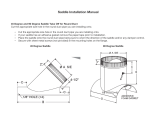
3. Select a location for the Humidistat.
Humidistat can be mounted on the return duct or on
the wall in the main living space. (Return duct
mounting is easiest for installing wiring.)
For return duct mounting, the Humidistat must be
mounted upstream from the Humidifier and Bypass
Collar so it is properly sensing the relative humidity
of the house. See Fig. 3.
Locate the control at least 8 in. upstream from the
Humidifier or Bypass Collar in the return air duct.
Fig. 3. Selecting duct location for
Humidistat and Humidifier.
4. Select a water supply location
Use either hard or soft water in the Humidifier.
Use either hot or cold water in the Humidifier.
Make sure 20 ft. of Plastic Water Tubing is long
enough to connect the water supply (saddle valve) to
the Humidifier.
Make sure saddle valve is accessible after
installation.
5. Locate 120V Electrical Outlet.
Select a location with access to an outlet. If an outlet
is not available, contact an electrician to have one
installed.
Make sure the 20 ft. of Thermostat Wire is adequate
to reach from the Humidifier motor to the Humidistat,
and the Humidistat to the Plug-in Transformer.
6. Locate Closest Floor Drain.
Select location with access to floor drain, if available.
Overflow drain is required in applications where
water overflow could cause flooding or property
damage.
If an overflow drain is needed, make sure Overflow
Tubing is long enough to reach from the Humidifier to
the floor drain.
NOTE: Every installation is unique. Please ensure that
water, power, and drain are available before install-
ing the device. In some cases, additional wire, tub-
ing, or duct may need to be purchased in order to
correctly install the Humidifier.
STEP 2: INSTALL HUMIDIFIER
WARNING
Hazardous Voltage.
Can cause personal injury or equipment damage.
Do not cut or drill into any air conditioning or electrical
accessory.
CAUTION
Sharp Edges Installation Hazard.
Can cause personal injury.
Wear gloves and safety glasses.
1. Turn off power to heating and cooling system.
2. Draw a level line on the duct in the location chosen for
the Humidifier. (Leveling assures optimal performance.)
See Fig. 4.
NOTE: There must be at least 1-1/2 in. of duct above the line
and 8-1/2 in. of duct below the line for proper installa-
tion. The duct must also be at least 11 in. wide for
proper installation.
Fig. 4. Marking template location.
3. Cut out template on page 22.
4. Tape template in position and trace around the template
with a marker.
5. Remove the template and carefully cut the rectangular
opening using tin snips. See Fig. 5. (Use a drill to start
the cut in the middle of the rectangle.)
ALTERNATE LOCATION
RETURN
AIR
RETURN
AIR
6 in. (152 mm)
MINIMUM
15 in. (381 mm)
MINIMUM
BEST
LOCATION
RETURN AIR DUCT
M13611
8 in. (203 mm)
MINIMUM
HE120 BY-PASS DRUM HUMIDIFIER
69-1860EF—01 6
Fig. 5. Cutting Humidifier opening.
6. Disassemble the Humidifier; remove the cover by lifting
up on the front edge and take out the drum components,
Water Pan, and Motor Plate.
7. Position the HE120 Humidifier Housing over the open-
ing (make sure it is level) and mark the five mounting
holes. See Fig. 6.
8. Remove the HE120 Humidifier Housing and pre-drill the
mounting holes using a 1/8 in. drill bit
9. Start the three #8 x 3/4 in. Sheet Metal Screws in the
top holes.
Fig. 6. Marking Mounting Hole locations.
10. Place the Humidifier Housing over the screws, level the
housing and tighten the three screws. See Fig. 7.
11. Secure the bottom of the Humidifier Housing using two
#8 x 3/4 in. Sheet Metal Screws.
Fig. 7. Mounting Humidifier.
12. Check that the Humidifier is level.
STARTING HOLE
M13618
MOUNTING HOLES
MOUNTING HOLES
M13619
HE120 BY-PASS DRUM HUMIDIFIER
7 69-1860EF—01
STEP 3: INSTALL BYPASS COLLAR
WARNING
Hazardous Voltage.
Can cause personal injury or equipment damage.
Do not cut or drill into any air conditioning or electrical
accessory.
CAUTION
Sharp Edges Installation Hazard.
Can cause personal injury.
Wear gloves and safety glasses.
NOTE: This Humidifier is supplied with an optional damper
to shut off air flow to the unit during the summer. This
damper is required for homes with air conditioning.
1. Position the 6 in. Bypass Collar on the duct so that all
six mounting holes are over the duct. (If you are install-
ing the optional damper, it is recommended that the flat
side of the Bypass Collar face up.) See Fig. 8.
Fig. 8. Mounting Bypass Collar (Optional Damper shown).
2. Trace around the inside of the collar and mark the loca-
tion of the mounting holes with a marker.
3. Remove the collar and carefully cut out the circular
opening using tin snips. See Fig. 9. (Use a drill to start
the cut in the middle of the circle. Cut in an outward spi-
ral to assist in controlling the cut.)
Fig. 9. Cutting Bypass hole.
OPTIONAL
DAMPER
FLAT SIDE OF
BYPASS COLLAR
M13620
STARTING
HOLE
6 IN. ROUND TEMPLATE
M20172
HE120 BY-PASS DRUM HUMIDIFIER
69-1860EF—01 8
4. Pre-drill the mounting holes using a 1/8 in. drill bit. If you
are installing the optional Damper, do not drill the hole
where the damper blade will swing. See Fig. 10.
Fig. 10. Drill pattern.
5. If you are installing the Optional Damper, place a #8 X
3/4 in. Sheet Metal Screw through the Bypass Collar
and Damper, as shown in Figure 11.
Fig. 11. Installing Optional Damper.
6. Place the Damper into position and install using
#8 x 3/4 in. Sheet Metal Screws.
7. If you installed the optional Damper, check that it opens
and closes correctly. (If necessary, tighten or loosen the
pivot screw to make it open and close correctly.)
NOTE: The Damper will not cover all of the opening in the
duct when closed. A small amount of leakage when
closed is acceptable.
OPTIONAL
DAMPER
PIVOT
POINT
BYPASS
COLLAR
DO NOT DRILL
THIS SCREW
LOCATION
IF OPTIONAL
DAMPER IS USED
M13615
CLOSE
OPEN
BENT UP EDGE OF
DAMPER
SHEET METAL
SCREW (PIVOT SCREW)
HOLE IN
DAMPER
FLAT SIDE
OF BYPASS
COLLAR
M13621
HE120 BY-PASS DRUM HUMIDIFIER
9 69-1860EF—01
STEP 4: INSTALL BYPASS DUCT
CAUTION
Sharp Edges Installation Hazard.
Can cause personal injury.
Wear gloves and safety glasses.
1. Carefully stretch out flexible Bypass Duct between
Bypass Collar and Humidifier. See Fig. 12.
Fig. 12. Installing flex duct.
2. Secure Bypass Duct to Bypass Collar using at least two
#8 x 3/4 in. Sheet Metal Screws. See Fig. 13. (Drill pilot
holes using 1/8 in. drill bit.)
Fig. 13. Connecting Bypass Duct to Bypass Collar.
3. Secure Bypass Duct to Humidifier using at least three
#8 x 3/4 in. Sheet Metal Screws. See Fig. 14. Drill pilot
holes using 1/8 in. drill bit.)
Fig. 14. Connecting Bypass Duct to Humidifier.
4. Seal both duct connections with Duct Tape. See Fig. 15.
IMPORTANT
Use only duct rated metallized duct tape to seal duct
connections.
Fig. 15. Sealing connections with tape.
5. If you installed the optional Damper, check that it opens
and closes correctly. (It may be necessary to cut or
move duct tape to allow proper operation of the
damper.)
HE120 BY-PASS DRUM HUMIDIFIER
69-1860EF—01 10
STEP 5: ASSEMBLE HUMIDIFIER
DRUM
1. Slide Closed Drum End over Drum Shaft with round
posts facing away from metal tabs. See Fig. 16. (Slots in
cone end should rest over metal tab.)
Fig. 16. Installing Closed Drum End.
2. Secure Closed Drum End to Drum Shaft using Spring
Retainer. See Fig. 17. (Squeeze spring ends slightly to
install.)
Fig. 17. Installing Spring Retainer.
3. Slide Humidifier Pad over closed drum end posts.
See Fig. 18.
Fig. 18. Installing Humidifier Pad.
4. Slide Open Drum End over Drum Shaft with round posts
inside Humidifier Pad. See Fig. 19.
5. Secure Open Drum End to shaft using Spring Retainer.
(Squeeze spring ends slightly to install.)
Fig. 19. Installing Open Drum End.
METAL
TAB
SLOT IN
CLOSED
DRUM END
M13622
SPRING
RETAINER
M13623
HE120 BY-PASS DRUM HUMIDIFIER
11 69-1860EF—01
STEP 6: ASSEMBLE HUMIDIFIER
1. Position the Bearing Bracket inside the Humidifier
Housing to the side where the Bypass Duct is con-
nected. Make sure the “U” shape is pointing up.
See Fig 20.
Fig. 20. Installing Bearing Bracket.
2. Snap the Bearing Bracket into place.
3. Position the Motor Plate on the opposite side of the
Humidifier Housing with the wires at the bottom.
See Fig 21.
Fig. 21. Installing Motor Plate.
4. Snap Motor Plate into place.
5. Place motor lead wires through bottom hole of Motor
Cover and snap into place on outside of Humidifier.
See Fig. 22.
Fig. 22. Installing Motor Cover.
6. Install the Float Valve to the Humidifier Housing on the
same side as the Motor Plate. See Fig. 24. (If the Float
Valve is already installed on the same side as the Motor
Plate, skip this step.)
a. Unscrew Float Valve Retaining Nut using a 1/2 in.
wrench. See Fig. 23.
b. Remove Float Valve from housing.
c. Place Float Valve Stem through “D” hole on same
side as the motor. See Fig. 24. (Float must be at
bottom.)
d. Place Float Valve Washer over Float Valve Stem
with recessed side of washer against the Humidifier
wall. See Fig. 25.
e. Secure Float Valve using Float Valve Retaining Nut
and tighten with 1/2 in. wrench. See Fig. 23.
IMPORTANT
The Float Valve must
be installed on the same side
of the Humidifier as the motor.
Fig. 23. Float Valve Retaining Nut.
SNAP TABS
INTO PLACE
“U” SHAPE FACES UP
M13624
M13625
MOTOR WIRES AT BOTTOM
M13610
VALVE SEAT
RETAINING NUT
HE120 BY-PASS DRUM HUMIDIFIER
69-1860EF—01 12
Fig. 24. Correct Float Valve position.
Fig. 25. Re-installing Float Valve.
7. Insert the Valve Hole Plug in the “D” hole on the oppo-
site side of the Float Valve. See Fig. 26.
Fig. 26. Installing Valve Hole Plug.
8. Insert the Drain Fitting into the bottom of the Humidifier
on the same side as the Bypass Duct. See Fig. 27.
Fig. 27. Installing Drain Fitting.
9. Place the Water Pan in the Humidifier Housing so Over-
flow Tube is above previously installed Drain Fitting.
See Fig. 28.
Fig. 28. Installing Water Pan.
10. Install Humidifier Drum by inserting motor coupling end
first, then snapping it into the bearing. See Fig. 29.
Fig. 29. Installing Humidifier Drum.
MOTOR
FLOAT VALVE
M13626
FLOAT VALVE
WASHER
(RECESSED SIDE)
FLOAT VALVE
RETAINING NUT
FLOAT VALVE STEM
HUMIDIFIER
HOUSING WALL
M13616
VALVE HOLE PLUG
M13627
DRAIN
FITTING
FLOAT
M13628
M13629
OVERFLOW
TUBE
DRAIN FITTING
(UNDERNEATH HUMIDIFIER HOUSING)
MOTOR
M13630
HE120 BY-PASS DRUM HUMIDIFIER
13 69-1860EF—01
11. Snap Humidifier Cover into place.
STEP 7: INSTALL DRAIN
CAUTION
Water Hazard.
Can result in water damage to property.
Install overflow drain in applications where water
damage can result from Float Valve failure.
1. Slide the 1/2 in. Overflow Clamp over the 3/8 in. inside
diameter, 1/2 in. outside diameter Overflow Tube.
See Fig. 30.
2. Push the Overflow Tube over the Drain Fitting.
3. Hand-tighten the Clamp around the Overflow Tube and
the Drain Fitting.
4. Fasten the Overflow Tube (can use duct tape) along the
route to the drain to prevent movement and ensure
downward slope.
5. Cut Overflow Tube to length so the tubing terminates at
the drain or bucket using a utility knife.
Fig. 30. Installing overflow tube.
IMPORTANT
Overflow Tube must follow downward slope from
Humidifier to drain for correct draining.
STEP 8: INSTALL SADDLE VALVE
CAUTION
Chemical Hazard.
Can cause personal injury or equipment damage.
Do not use any line connected to an air conditioner.
Do not use gas line.
IMPORTANT
Do not turn handle before or while installing the sad-
dle valve. Be sure the piercing lance does not pro-
trude beyond the rubber gasket. Failure to do this
may damage piercing needle.
To prevent debris from clogging the Float Valve, do
not install the saddle valve with the handle pointing
toward the floor.
NOTE: This saddle valve can be used with either copper or
steel/brass pipe. Please refer to the correct instruc-
tions for your application.
Copper Pipe:
1. Shut off the water. (Either hot or cold water and either
hard or softened water can be used in the Humidifier.)
2. Turn handle counter clockwise until piercing lance is
below the rubber gasket. See Fig. 31.
Fig. 31. Positioning Saddle Valve for installation with
Copper Pipe.
3. Assemble saddle valve over copper tube using
#10 x 1-3/4 in. machine screws. See Fig. 32.
Fig. 32. Installing Saddle Valve.
M20177
LANCE
BELOW
GASKET
M13631
M20175
SCREW DRIVER
WATER LINE
HE120 BY-PASS DRUM HUMIDIFIER
69-1860EF—01 14
a. For 3/8 in. diameter copper tubing use bracket side
with projections to prevent distorting tube.
See Fig. 33.
b. Use “V” side of bracket for all other size tubing.
Fig. 33. Saddle Valve Bracket installation.
4. Tighten screws evenly – brackets should be parallel.
Tighten firmly.
Steel or Brass Pipe:
1. Shut off water supply and drain the line.
2. Drill a 3/16 in. hole in pipe. Use a cordless drill to avoid
shock hazard.
3. Turn the handle to expose the lance beyond the gasket
no more than 3/16 in. See Fig. 34.
4. Place valve body over hole such that lance fits into the
drilled hole in the pipe.
5. Tighten bottom clamp evenly. Brackets should be paral-
lel. See Fig. 32.
6. Turn handle clockwise to close the valve.
7. Open water supply.
Fig. 34. Positioning Saddle Valve for installation
with steel pipe.
BRACKET SIDE
(USE WITH 3/8 IN. DIAMETER
COPPER TUBING)
“V” SIDE OF BRACKET
(USE WITH LARGER
DIAMETER TUBING)
M13633
LANCE ABOVE
GASKET
3/16 IN. MAXIMUM
M13632
HE120 BY-PASS DRUM HUMIDIFIER
15 69-1860EF—01
STEP 9: INSTALL WATER LINE
CAUTION
Water Hazard.
Can result in water damage to property.
Properly secure water line along route to prevent
movement and provide support at compression nut
joints.
IMPORTANT
Be sure to check with your local building codes to
determine if the Plastic Water Tubing packaged with
the Humidifier is appropriate for your installation.
(Some local building codes require 1/4 in. copper
tubing to be used.)
1. Place Brass Compression Nut over Plastic Water Tub-
ing. See Fig. 35.
Fig. 35. Connecting plastic water line.
2. Slide the Plastic Compression Sleeve over the Tubing.
3. Install Brass Insert into end of Plastic Water Tubing.
NOTE: To prevent leaking, use Plastic Compression Sleeve
only with Plastic Tubing and Copper Compression
Sleeve only with copper tubing.
4. Insert the tubing into the saddle valve fitting.
5. Support the valve while tightening the Brass Compres-
sion Nut with an 1/2 in. open-end or adjustable wrench.
6. Route Plastic Water Tubing from saddle valve to Humid-
ifier Float Valve Fitting. Secure Plastic Water Tubing
along the route with Tube Retainers to prevent move-
ment.
7. Cut Plastic Water Tubing to length. (Do not cut tubing
too short.)
8. Repeat steps A through E to attach Tubing to Float
Valve Fitting.
M20176
BRASS COMPRESSION NUT
PLASTIC
COMPRESSION
RING
BRASS INSERT
HE120 BY-PASS DRUM HUMIDIFIER
69-1860EF—01 16
STEP 10: INSTALL HUMIDISTAT
WARNING
Hazardous Voltage.
Can cause personal injury of equipment damage.
Do not cut or drill into any air conditioning or electrical
accessory.
CAUTION
Sharp Edges Installation Hazard.
Can cause personal injury.
Wear gloves and safety glasses.
NOTE: The Humidistat included with this kit can be mounted
on the return air duct (recommended) or mounted on
a wall inside the home. Instructions are included for
both wall and duct mounting.
Duct Mounting (Recommended):
IMPORTANT
If mounting near an elbow area, keep the control
8 in. upstream from the elbow so the element is
exposed to the normal airflow. See Fig. 3 on page 5.
1. Locate the Humidistat in the return air (cold) duct at
least 8 in. upstream from the Humidifier or the Humidi-
fier Bypass Collar.
2. Remove the backing on the Humidistat Mounting Tem-
plate and adhere the Humidistat mounting template in a
horizontal position on the duct. See Fig. 36.
Fig. 36. Securing Mounting Template.
3. Refer to Fig. 37, and use the following steps to cut the
Humidistat mounting hole.
a. Drill a 1/2 in. hole in the center of the template.
b. Use tin snips to cut the opening along the dotted
lines.
c. Drill four 7/64 in. mounting holes
Fig. 37. Cutting Humidistat opening.
4. Remove the protective backing from the Humidistat
Gasket and mount the Gasket on the shaded area of
the template. See Fig. 38.
Fig. 38. Installing Gasket.
M13606
DRILL A 1/2 IN. (13 mm)
HOLE IN CENTER
OF TEMPLATE.
USE A TINSNIP
TO ENLARGE
THE OPENING TO
THE D0TTED LINE.
DRILL FOUR
7/64 IN. (3 mm)
MOUNTING HOLES.
TEMPLATE
GASKET
M13607
MOUNT GASKET
ON SHADED AREA
OF TEMPLATE.
HE120 BY-PASS DRUM HUMIDIFIER
17 69-1860EF—01
5. Unscrew Back Cover of the Humidistat and remove.
See Fig. 39.
Fig. 39. Removing Humidistat Back Cover.
6. Snap two Screw Terminals over the blade terminals on
the Control Assembly. See Fig. 40
Fig. 40. Installing Screw Terminals.
7. Connect the two low voltage control wires to the Screw
Terminals on the Control Assembly. See Fig. 41.
Fig. 41. Wiring Humidistat.
8. Tuck excess wire into the recessed area on the back of
the Base Plate.
9. Use four #6 x 1 in. Sheet Metal Screws to secure the
assembly to the duct through the mounting holes.
See Fig. 42.
Fig. 42. Securing Humidistat to Duct.
10. Push the Setpoint Dial knob onto the control shaft.
Wall Mounting:
IMPORTANT
Mount the control in an area with average room tem-
perature and relative humidity.
1. Locate the control about 5 ft. above the floor on an
inside wall. See Fig. 43.
Fig. 43. Selecting Humidistat location.
2. Drill a 3/8 in. hole in the wall
3. Run 18-gauge two-strand thermostat wire to the loca-
tion and pull about 6 in. of wire through the hole.
M12841A
CONTROL
ASSEMBLY
SETPOINT
DIAL
GASKET
DUCT
60
10
SHEET METAL
SCREWS (4)
5 FEET
[1.5 METERS]
YES
NO
NO
NO
M19925
HE120 BY-PASS DRUM HUMIDIFIER
69-1860EF—01 18
4. Plug the hole with nonflammable insulation to prevent
drafts from affecting the control.
5. Unscrew the Back Cover of Humidistat and remove.
See Fig. 39.
6. Unscrew the two Base Plate screws and remove the
Control Assembly. See Fig. 44.
Fig. 44. Removing Control Assembly from Base Plate.
7. Snap two Screw Terminals over the blade terminals on
the Control Assembly. See Fig. 40.
8. To assemble control for wall mounting (See Fig. 45):
a. Drill clearance hole in plastic Base Plate for low volt-
age wiring with 3/8 in. drill bit.
b. Turn over the Base Plate so text faces the wall.
c. Place the Control Assembly on the Base Plate with
the dial shaft facing away from the plate.
d. Screw the Control Assembly to the Base Plate using
the two Base Plate screws.
Fig. 45. Mounting Humidistat.
9. Position the Base Plate horizontally over the wire and
pull the wire through the hole.
10. Connect the wires to the Screw Terminals on the Con-
trol Assembly. See Fig. 41 on page 17.
11. Secure Base Plate to the wall using four #6 x 1 in.
Sheet Metal Screws. See Fig. 46.
Fig. 46. Mounting Humidistat.
12. Remove the backing and adhere the Humidistat Label
to the recessed area of the front of the Humidistat
Cover. See Fig. 47.
Fig. 47. Adhere Humidistat Cover Label.
13. Secure the Humidistat Cover to the Control Assembly
using one 3/8 in. screw. See Fig. 48
14. Push the Setpoint Dial onto the control shaft.
Fig. 48. Assembling Humidistat Cover.
BASE PLATE SCREWS
M13634
M13612
BASE PLATE
CONTROL ASSEMBLY
DRILL 3/8 IN.
CLEARANCE
HOLE IN PLASTIC
BASE PLATE
SCREWS (2)
DIAL SHAFT
M13635
BASE PLATE
WITH CONTROL
ASSEMBLY
MOUNTED
SHEET METAL
SCREWS (4)
WALL
ALIGN HOLE IN COVER
WITH HOLE IN LABEL
FOR CORRECT PLACEMENT
M13636
60
10
M13614
BASEPLATE
COVER
SETPOINT DIAL
3/8 IN.
SCREW
HE120 BY-PASS DRUM HUMIDIFIER
19 69-1860EF—01
STEP 11: WIRING
WARNING
Hazardous Voltage.
Can cause personal injury of equipment damage.
Disconnect power supply before installing or servicing
equipment.
IMPORTANT
All wiring must comply with applicable code, ordi-
nances and regulations.
1. Run the 18-gauge two-strand Thermostat Wire from the
Humidistat to the Transformer near a wall outlet and cut
to length. (Leave adequate wire at both ends for con-
nection.)
NOTE: Wire is already connected to the Humidistat.
2. Run the 18-gauge two-strand Thermostat Wire from the
Humidifier to the Transformer and cut to length. (Leave
adequate wire at both ends for connection.)
3. At the Humidifier, connect the red and white conductors
to the two motor leads using wire nuts. See Fig. 49.
Fig. 49. Wiring motor.
4. At the transformer, connect both white conductors to the
two transformer terminals. See Fig. 50.
Fig. 50. Wiring Transformer.
5. Use a wire nut to connect the red conductors together.
6. Secure thermostat wire along route to prevent move-
ment (can use duct tape).
7. Check wiring per Fig. 51.
Fig. 51. Wiring diagram.
H
u
m
id
i
t
y
C
o
n
t
r
o
l
R
é
g
u
l
a
te
u
r
d
'h
u
m
i
d
i
t
é
-
2
0
¡
F
-
1
0
¡
F
0
¡
F
+
1
0
¡
F
+
2
0
¡
F
O
v
e
r
2
0
¡
F
1
5
%
2
0
%
2
5
%
3
0
%
3
5
%
4
0
%
H
U
M
I
D
I
T
Y
S
E
T
T
I
N
G
O
U
T
D
O
O
R
T
E
M
P
E
R
A
T
U
R
E
-
3
0
¡
C
-
2
5
¡
C
-
2
0
¡
C
-
1
0
¡
C
-
5
¡
C
O
v
e
r
0
¡
C
M13613
TRANSFORMER
RED
WHITE
RED
WHITE
HUMIDIFIER
DRIVE
MOTOR
HUMIDISTAT
HE120 BY-PASS DRUM HUMIDIFIER
69-1860EF—01 20
STEP 12: TESTING AND CHECKOUT
1. Complete the following checklist:
Humidifier is level.
Bypass Collar is secured with Sheet Metal Screws.
Damper is open (If installed).
Control wiring was reviewed per wiring diagram. (Fig. 51).
Water supply line has no kinks.
Overflow drain line slopes continuously down, does not
have kinks, and ends at floor drain or bucket.
2. Plug in transformer.
3. Open water supply. (Turn saddle valve clockwise until
you feel it is firmly seated, then turn valve counter clock-
wise to start the water flow.)
4. Remove Humidifier Cover and verify that Water Pan fills
and water shuts off before water enters Overflow Tube.
5. Adjust water level to 1-3/8 in. deep by turning the
adjustment screw on the Float Valve. See Fig. 52.
(Clockwise to lower water level, counter-clockwise to
raise water level.)
6. Turn Humidistat “ON”.
7. Make sure the Humidistat Drum Assembly is rotating.
8. Snap Humidifier cover into place.
9. Check for water leaks at the saddle valve fitting and
Float Valve fitting. (If necessary, tighten fittings.)
10. Reset the Humidistat to a comfortable setting for auto-
matic operation. (See owner’s manual for more details.)
Fig. 52. Adjusting water level.
LOWER
WATER LEVEL
(CLOCKWISE)
RAISE
WATER LEVEL
(COUNTER-
CLOCKWISE)
M13637
  • Page 1 1
  • Page 2 2
  • Page 3 3
  • Page 4 4
  • Page 5 5
  • Page 6 6
  • Page 7 7
  • Page 8 8
  • Page 9 9
  • Page 10 10
  • Page 11 11
  • Page 12 12
  • Page 13 13
  • Page 14 14
  • Page 15 15
  • Page 16 16
  • Page 17 17
  • Page 18 18
  • Page 19 19
  • Page 20 20
  • Page 21 21
  • Page 22 22
  • Page 23 23
  • Page 24 24
  • Page 25 25
  • Page 26 26
  • Page 27 27
  • Page 28 28
  • Page 29 29
  • Page 30 30
  • Page 31 31
  • Page 32 32
  • Page 33 33
  • Page 34 34
  • Page 35 35
  • Page 36 36
  • Page 37 37
  • Page 38 38
  • Page 39 39
  • Page 40 40
  • Page 41 41
  • Page 42 42
  • Page 43 43
  • Page 44 44
  • Page 45 45
  • Page 46 46
  • Page 47 47
  • Page 48 48

Honeywell HE120 User manual

Type
User manual
This manual is also suitable for

Ask a question and I''ll find the answer in the document

Finding information in a document is now easier with AI

in other languages