SAFETY WARNING
Only qualified personnel should install and service the equipment. The installation,
starting up, and servicing of heating, ventilating, and air-conditioning equipment can
be hazardous and requires specific knowledge and training. Improperly installed,
adjusted or altered equipment by an unqualified person could result in death or
serious injury. When working on the equipment, observe all precautions in the
literature and on the tags, stickers, and labels that are attached to the equipment.
132
45
©2022 Trane
6
Installation Instructions
Symbio™ 500 Programmable
Controller
The Symbio 500 multi-purpose programmable controller is used in a range
of terminal applications.
Warnings, Cautions, and Notices
Read this manual thoroughly before operating or servicing this unit. Safety
advisories appear throughout this manual as required. Your personal safety
and the proper operation of this machine depend upon the strict observance
of these precautions.
Important Environmental Concerns
Scientific research has shown that certain man-made chemicals can affect
the earth’s naturally occurring stratospheric ozone layer when released to
the atmosphere. In particular, several of the identified chemicals that may
affect the ozone layer are refrigerants that contain Chlorine, Fluorine and
Carbon (CFCs) and those containing Hydrogen, Chlorine, Fluorine and
Carbon (HCFCs). Not all refrigerants containing these compounds have the
same potential impact to the environment. Trane advocates the responsible
handling of all refrigerants-including industry replacements for CFCs such
as HCFCs and HFCs.
Important Responsible Refrigerant Practices
Trane believes that responsible refrigerant practices are important to the
environment, our customers, and the air conditioning industry. All
technicians who handle refrigerants must be certified according to local
rules. For the USA, the Federal Clean Air Act (Section 608) sets forth the
requirements for handling, reclaiming, recovering and recycling of certain
refrigerants and the equipment that is used in these service procedures. In
addition, some states or municipalities may have additional requirements
that must also be adhered to for responsible management of refrigerants.
Know the applicable laws and follow them.
The three types of advisories are defined as follows:
WARNING Indicates a potentially hazardous situation which,
if not avoided, could result in death or serious
injury.
CAUTION Indicates a potentially hazardous situation which,
if not avoided, could result in minor or moderate
injury. It could also be used to alert against unsafe
NOTICE Indicates a situation that could result in
equipment or property-damage only accidents.
WARNING
Proper Field Wiring and Grounding Required!
Failure to follow code could result in death or serious injury. All field wiring
MUST be performed by qualified personnel. Improperly installed and grounded
field wiring poses FIRE and ELECTROCUTION hazards. To avoid these hazards,
you MUST follow requirements for field wiring installation and grounding as
described in NEC and your local/state/national electrical codes.
WARNING
Personal Protective Equipment (PPE) Required!
Failure to wear proper PPE for the job being undertaken could result in death or
serious injury. Technicians, in order to protect themselves from potential
electrical, mechanical, and chemical hazards, MUST follow precautions in this
manual and on the tags, stickers, and labels, as well as the instructions below:
•Before installing/servicing this unit, technicians MUST put on all PPE
required for the work being undertaken (Examples; cut resistant
gloves/sleeves, butyl gloves, safety glasses, hard hat/bump cap, fall
protection, electrical PPE and arc flash clothing). ALWAYS refer to
appropriate Safety Data Sheets (SDS) and OSHA guidelines for proper PPE.
•When working with or around hazardous chemicals, ALWAYS refer to the
appropriate SDS and OSHA/GHS (Global Harmonized System of
Classification and Labeling of Chemicals) guidelines for information on
allowable personal exposure levels, proper respiratory protection and
handling instructions.
•If there is a risk of energized electrical contact, arc, or flash, technicians
MUST put on all PPE in accordance with OSHA, NFPA 70E, or other country-
specific requirements for arc flash protection, PRIOR to servicing the unit.
NEVER PERFORM ANY SWITCHING, DISCONNECTING, OR VOLTAGE
TESTING WITHOUT PROPER ELECTRICAL PPE AND ARC FLASH CLOTHING.
ENSURE ELECTRICAL METERS AND EQUIPMENT ARE PROPERLY RATED
FOR INTENDED VOLTAGE.
Copyright
This document and the information in it are the property of Trane, and may
not be used or reproduced in whole or in part without written permission.
Trane reserves the right to revise this publication at any time, and to make
changes to its content without obligation to notify any person of such
revision or change.
Trademarks
All trademarks referenced in this document are the trademarks of their
respective owners.
Ordering Numbers
WARNING
Follow EHS Policies!
Failure to follow instructions below could result in death or serious injury.
• All Trane personnel must follow the company’s Environmental, Health and
Safety (EHS) policies when performing work such as hot work, electrical, fall
protection, lockout/tagout, refrigerant handling, etc. Where local
regulations are more stringent than these policies, those regulations
supersede these policies.
•Non-Trane personnel should always follow local regulations.
Order Number Description
BMSY500AAA0100011 Symbio 500 Programmable Controller
BMSY500UAA0100011 Symbio 500 Programmable Controller, Made in USA
Storage/Operating Specifications
Agency Compliance
•UL60730-1 PAZX (Open Energy Management Equipment)
•UL94-5V Flammability
•CE Marked
•UKCA Marked
•FCC Part 15, Subpart B, Class B Limit
•VCCI-CISPR 32:2016: Class B Limit
•AS/NZS CISPR 32:2015: Class B Limit
•CAN ICES-003(B)/NMB-003(B)
Storage
Temperature: -67°F to 203°F (-55°C to 95°C)
Relative
Humidity:
Between 5% to 95% (non-condensing)
Operating
Temperature: -40°F to 158°F (-40°C to 70°C)
Humidity: Between 5% to 95% (non-condensing)
Power: 20.4–27.6 Vac (24 Vac, ±15% nominal) 50–60 Hz, 24 VA
For specifics on transformer sizing, see BAS-SVX090.
Mounting
Weight of
Controller:
Mounting surface must support 0.80 lb. (0.364 kg)
Environmental
Rating
(Enclosure):
NEMA 1
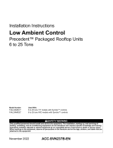
Dimensions/Mounting/Removing the Controller
September 2022 BAS-SVN231B-EN
Wiring Requirements
To ensure proper operation of the controller, install the power supply circuit
in accordance with the following guidelines:
•The controller must receive AC power from a dedicated power circuit;
failure to comply may cause the controller to malfunction.
•A dedicated power circuit disconnect switch must be near the
controller, easily accessible by the operator, and marked as the
disconnecting device for the controller.
•DO NOT run AC power wires in the same wire bundle with input/output
wires; failure to comply may cause the controller to malfunction due to
electrical noise.
•18 AWG copper wire is recommended for the circuit between the
transformer and the controller.
Transformer Recommendations
The controller can be powered with 24 Vac. Use of a 24 Vac power supply
is recommended in order to use the spare 24 Vac outputs for powering
relays and TRIACs.
•AC transformer requirements: UL listed, Class 2 power transformer, 24
Vac ±15%, device max load 24 VA. The transformer must be sized to
provide adequate power to the controller and outputs.
•CE-compliant installations: The transformer must be CE marked and
SELV compliant per IEC standards.
A separate transformer is recommended for each controller. The line input
to the transformer must be equipped with a circuit breaker sized to handle
the maximum transformer line current. If a single transformer is shared by
multiple controllers:
•The transformer must have sufficient capacity
•Polarity must be maintained for every controller powered by the
transformer
NOTICE
Equipment Damage!
Sharing 24 Vac power between controllers could result in equipment damage.
To mount device:
1. Hook device over
top of DIN rail.
2. Gently push on
lower half of device
in the direction of
arrow until the
release clip clicks
into place.
To remove/reposition device:
1. Disconnect all connectors before
removing or repositioning.
2. Insert screwdriver into slotted release clip
and gently pry upward with the
screwdriver to disengage the clip.
3. While holding tension on the clip, lift
device upward to remove or reposition.
4. If repositioned, push on the device until the
release clip clicks back into place to
secure the device on the DIN rail.
Slotted release clip
shown from back side
NOTICE
Equipment Damage!
Do not use excessive force to install the controller on the DIN rail. Excessive
force could result in damage to the plastic enclosure. If using another
manufacturer’s DIN rail, follow their recommended installation.
WARNING
Hazard Voltage!
Disconnect all electric power, including remote disconnects, before servicing.
Follow proper lockout/tag out procedures to ensure the power cannot be
inadvertently energized. Failure to disconnect power before servicing could
result in serious injury or death.
CAUTION
Personal Injury and Equipment Damage!
After installation, ensure to check that the 24 Vac transformer is grounded
through the controller. Failure to check could result in personal injury and/or
damage to equipment. Measure the voltage between chassis ground and any
ground terminal on the controller. Expected result: Vac <4.0 volt.
2.37 in.
(60.1 mm)
1.89 in.
(48 mm)
4.00 in.
(101.6 mm)
End View
1.79 in.
(45.4 mm)