Trane BAS-SVN231C Symbio 500 Programmable Controller User manual
- Type
- User manual

SAFETY WARNING
Only qualified personnel should install and service the equipment. The installation,
starting up, and servicing of heating, ventilating, and air-conditioning equipment can
be hazardous and requires specific knowledge and training. Improperly installed,
adjusted or altered equipment by an unqualified person could result in death or
serious injury. When working on the equipment, observe all precautions in the
literature and on the tags, stickers, and labels that are attached to the equipment.
132
45
©2023 Trane
6
Installation Instructions
Symbio™ 500 Programmable
Controller
The Symbio 500 multi-purpose programmable controller is used in a range of
terminal applications.
Warnings, Cautions, and Notices
Read this manual thoroughly before operating or servicing this unit. Safety
advisories appear throughout this manual as required. Your personal safety and
the proper operation of this machine depend upon the strict observance of these
precautions.
Important Environmental Concerns
Scientific research has shown that certain man-made chemicals can affect the
earth’s naturally occurring stratospheric ozone layer when released to the
atmosphere. In particular, several of the identified chemicals that may affect the
ozone layer are refrigerants that contain Chlorine, Fluorine and Carbon (CFCs)
and those containing Hydrogen, Chlorine, Fluorine and Carbon (HCFCs). Not all
refrigerants containing these compounds have the same potential impact to the
environment. Trane advocates the responsible handling of all refrigerants-
including industry replacements for CFCs such as HCFCs and HFCs.
Important Responsible Refrigerant Practices
Trane believes that responsible refrigerant practices are important to the
environment, our customers, and the air conditioning industry. All technicians
who handle refrigerants must be certified according to local rules. For the USA,
the Federal Clean Air Act (Section 608) sets forth the requirements for handling,
reclaiming, recovering and recycling of certain refrigerants and the equipment
that is used in these service procedures. In addition, some states or
municipalities may have additional requirements that must also be adhered to for
responsible management of refrigerants. Know the applicable laws and follow
them.
The three types of advisories are defined as follows:
WARNING Indicates a potentially hazardous situation which, if
not avoided, could result in death or serious injury.
CAUTION Indicates a potentially hazardous situation which, if
not avoided, could result in minor or moderate injury.
It could also be used to alert against unsafe practices.
NOTICE Indicates a situation that could result in equipment or
property-damage only accidents.
WARNING
Proper Field Wiring and Grounding Required!
Failure to follow code could result in death or serious injury. All field wiring
MUST be performed by qualified personnel. Improperly installed and grounded
field wiring poses FIRE and ELECTROCUTION hazards. To avoid these
hazards, you MUST follow requirements for field wiring installation and
grounding as described in NEC and your local/state/national electrical codes.
WARNING
Personal Protective Equipment (PPE) Required!
Failure to wear proper PPE for the job being undertaken could result in death
or serious injury. Technicians, in order to protect themselves from potential
electrical, mechanical, and chemical hazards, MUST follow precautions in this
manual and on the tags, stickers, and labels, as well as the instructions below:
• Before installing/servicing this unit, technicians MUST put on all PPE
required for the work being undertaken (Examples; cut resistant
gloves/sleeves, butyl gloves, safety glasses, hard hat/bump cap, fall
protection, electrical PPE and arc flash clothing). ALWAYS refer to
appropriate Safety Data Sheets (SDS) and OSHA guidelines for proper PPE.
• When working with or around hazardous chemicals, ALWAYS refer to the
appropriate SDS and OSHA/GHS (Global Harmonized System of
Classification and Labeling of Chemicals) guidelines for information on
allowable personal exposure levels, proper respiratory protection and
handling instructions.
• If there is a risk of energized electrical contact, arc, or flash, technicians
MUST put on all PPE in accordance with OSHA, NFPA 70E, or other country-
specific requirements for arc flash protection, PRIOR to servicing the unit.
NEVER PERFORM ANY SWITCHING, DISCONNECTING, OR VOLTAGE
TESTING WITHOUT PROPER ELECTRICAL PPE AND ARC FLASH
CLOTHING. ENSURE ELECTRICAL METERS AND EQUIPMENT ARE
PROPERLY RATED FOR INTENDED VOLTAGE.
Copyright
This document and the information in it are the property of Trane, and may not
be used or reproduced in whole or in part without written permission. Trane
reserves the right to revise this publication at any time, and to make changes to
its content without obligation to notify any person of such revision or change.
Trademarks
All trademarks referenced in this document are the trademarks of their respective
owners.
Ordering Numbers
WARNING
Follow EHS Policies!
Failure to follow instructions below could result in death or serious injury.
• All Trane personnel must follow the company’s Environmental, Health and
Safety (EHS) policies when performing work such as hot work, electrical, fall
protection, lockout/tagout, refrigerant handling, etc. Where local
regulations are more stringent than these policies, those regulations
supersede these policies.
• Non-Trane personnel should always follow local regulations.
Order Number Description
BMSY500AAA0100011 Symbio 500 Programmable Controller
BMSY500UAA0100011 Symbio 500 Programmable Controller, Made in USA
Storage/Operating Specifications
Agency Compliance
• UL60730-1 PAZX (Open Energy Management Equipment)
• UL94-5V Flammability
•CE Marked
•UKCA Marked
• FCC Part 15, Subpart B, Class B Limit
• VCCI-CISPR 32:2016: Class B Limit
• AS/NZS CISPR 32:2015: Class B Limit
• CAN ICES-003(B)/NMB-003(B)
Storage
Temperature: -67°F to 203°F (-55°C to 95°C)
Relative Humidity: Between 5% to 95% (non-condensing)
Operating
Temperature: -40°F to 158°F (-40°C to 70°C)
Humidity: Between 5% to 95% (non-condensing)
Power: 20.4–27.6 Vac (24 Vac, ±15% nominal) 50–60 Hz, 24 VA
For specifics on transformer sizing, see BAS-SVX090.
Mounting Weight of
Controller:
Mounting surface must support 0.80 lb. (0.364 kg)
Environmental
Rating (Enclosure):
NEMA 1
Plenum Rating: Not plenum rated. The Symbio 500 must be mounted withing a rated
enclosure when installed in a plenum.
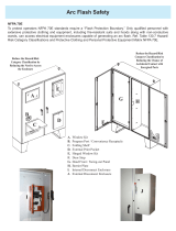
Dimensions/Mounting/Removing the Controller
April 2022 BAS-SVN231C-EN
Wiring Requirements
To ensure proper operation of the controller, install the power supply circuit in
accordance with the following guidelines:
• The controller must receive AC power from a dedicated power circuit; failure
to comply may cause the controller to malfunction.
• A dedicated power circuit disconnect switch must be near the controller,
easily accessible by the operator, and marked as the disconnecting device
for the controller.
• DO NOT run AC power wires in the same wire bundle with input/output wires;
failure to comply may cause the controller to malfunction due to electrical
noise.
• 18 AWG copper wire is recommended for the circuit between the transformer
and the controller.
Transformer Recommendations
The controller can be powered with 24 Vac. Use of a 24 Vac power supply is
recommended in order to use the spare 24 Vac outputs for powering relays and
TRIACs.
• AC transformer requirements: UL listed, Class 2 power transformer, 24 Vac
±15%, device max load 24 VA. The transformer must be sized to provide
adequate power to the controller and outputs.
• CE-compliant installations: The transformer must be CE marked and SELV
compliant per IEC standards.
A separate transformer is recommended for each controller. The line input to the
transformer must be equipped with a circuit breaker sized to handle the
maximum transformer line current. If a single transformer is shared by multiple
controllers:
• The transformer must have sufficient capacity
• Polarity must be maintained for every controller powered by the transformer
NOTICE
Equipment Damage!
Sharing 24 Vac power between controllers could result in equipment damage.
To mount device:
1. Hook device over top
of DIN rail.
2. Gently push on lower
half of device in the
direction of arrow
until the release clip
clicks into place.
To remove/reposition device:
1. Disconnect all connectors before removing or
repositioning.
2. Insert screwdriver into slotted release clip and
gently pry upward with the screwdriver to
disengage the clip.
3. While holding tension on the clip, lift device
upward to remove or reposition.
4. If repositioned, push on the device until the
release clip clicks back into place to secure
the device on the DIN rail.
Slotted release clip shown
from back side
NOTICE
Equipment Damage!
Do not use excessive force to install the controller on the DIN rail. Excessive
force could result in damage to the plastic enclosure. If using another
manufacturer’s DIN rail, follow their recommended installation.
WARNING
Hazard Voltage!
Disconnect all electric power, including remote disconnects, before servicing.
Follow proper lockout/tag out procedures to ensure the power cannot be
inadvertently energized. Failure to disconnect power before servicing could
result in serious injury or death.
CAUTION
Personal Injury and Equipment Damage!
After installation, ensure to check that the 24 Vac transformer is grounded
through the controller. Failure to check could result in personal injury and/or
damage to equipment. Measure the voltage between chassis ground and any
ground terminal on the controller. Expected result: Vac <4.0 volt.
2.37 in.
(60.1 mm)
1.89 in.
(48 mm)
4.00 in.
(101.6 mm)
End View
1.79 in.
(45.4 mm)

8
79
10 11
6
©2023 Trane
Trane has a policy of continuous product and product data improvement and reserves the
right to change design and specifications without notice. We are committed to using
environmentally conscious print practices.
Trane - by Trane Technologies (NYSE: TT), a global climate innovator - creates
comfortable, energy efficient indoor environments for commercial and residential
applications. For more information, please visit trane.com or tranetechnologies.com.
12
Important: If a technician inadvertently reverses polarity between controllers powered by the
same transformer, a difference of 24 Vac will occur between the grounds of each
controller. The following symptoms could result:
•Partial or full loss of communication on the entire BACnet® link
•Improper function of controller outputs
•Damage to the transformer or a blown transformer fuse
Wiring AC Power
To wire AC power:
1. Connect both secondary wires from the 24 Vac transformer to the XFMR
terminals on the device.
2. Ensure the device is properly grounded.
Important: This device must be grounded for proper operation! The factory-supplied
ground wire must be connected from any chassis ground connection on
the device ( ) to an appropriate earth ground ( ). The chassis ground
connection used may be the 24 Vac transformer input at the device, or any
other chassis ground connection on the device.
Note: The device is not grounded through the DIN rail connection.
Rotary Address
Switches
24 Vac
Transformer
Note: A pigtail connection should be used
between the chassis ground on the device
and an earth ground, if the device is not
grounded through one leg of the transformer
wiring.
Startup and Power Check
1. Verify that the 24 Vac connector and the chassis ground are properly wired.
2. Each device must have a unique and valid address. The address is set by using
the rotary address switches. Valid addresses are 001 through 127 for BACnet
MS/TP applications and 001 through 980 for Trane Air-Fi and BACnet IP
applications.
Important: A duplicate address or a 000 address will cause communication problems in a
BACnet link: The Tracer SC+ will not discover all devices on the link and the installation process
will fail after discovery.
3. Remove the lockout/tagout from the line voltage power to the electrical cabinet.
4. Apply power to the controller and observe the power check sequence that
follows:
The power LED lights red for 1 second. Then it changes to green, indicating that
the unit is properly booted and ready for application code. Flashing red indicates
that a fault conditions exists. The Tracer® TU service tool can be used to check
for fault conditions after application code and TGP2 programming have been
loaded.
Input/Output Wiring
NOTICE
Equipment Damage!
Remove power to the controller before making input/output connections. Failure to
do so may cause damage to the controller, power transformer, or input/output
devices due to inadvertent connections to power circuits.
Pre-power checks of input/output devices should be performed according to the
Symbio 500 IOM (BAS-SVX090). Maximum wire lengths are as follows:
Tug Test for Terminal Connectors
If using terminal connectors for wiring, strip the wires to expose 0.28 in (7 mm)
of bare wire. Insert each wire into a terminal connector and tighten the terminal
screws. A tug test is recommended after tightening terminal screws to ensure
that all wires are secure.
BACnet MS/TP Link Wiring
BACnet MS/TP link wiring must be field-supplied and installed in compliance with
NEC and local codes. In addition, the wire must be the following type: low
capacitance, 18 gauge, stranded, tinned copper, shielded, twisted pair. Polarity
must be maintained between all devices on the link.
BACnet IP Wiring
The Symbio 500 supports BACnet IP. The device requires a category 5E or
newer Ethernet cable with an RJ-45 plug connector. The cable can be plugged
into either port on the controller.
Maximum Wire Lengths
Type Inputs Outputs
Binary 1,000 ft (300 m) 1,000 ft (300 m)
0–20 mA 1,000 ft (300 m) 1,000 ft (300 m)
0–10 Vdc 300 ft (100 m) 300 ft (100 m)
Thermistor/Resistive 300 ft (100 m) Not Applicable
• All wiring must be in accordance with the NEC and local codes.
• Use only 18–22 AWG (1.02 mm to 0.65 mm diameter), stranded, tinned-copper, shielded,
twisted-pair wire.
• Analog and 24 Vdc output wiring distances are dependent on the receiving unit specifications.
• DO NOT run input/output wires or communication wires in the same wire bundle with AC power
wires.
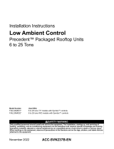
Examples of Wiring
0–20 mA
output
(Load < 500
W)
Binary
input
Thermistor
Humidity
0–20 mA
CO2
0-10 Vdc
or
4-20 mA
Analog Outputs/Binary Inputs Universal Inputs Analog Inputs
Zone sensor
1
4
3
2
.
Analog Input/Output Wiring Terminals Are Top Tier
Binary Input/Output Wiring Terminals Are Lower Tier
24 Vdc Power Supply (Output Only)
High-side Switching; typical wiring method
TRIAC Supply Wiring
Low-side Switching; minimizes the risk of burning up
binary outputs due to inadvertent shorts to the ground.
BAS-SVN231C-EN 08 Apr 2023
Supersedes BAS-SVN231B-EN (Sep 2022)
Input/Output Specifications
Input/Output type Qty Types Range Notes
Analog Input
(AI1 to AI5)) 5
Thermistor 10kΩ – Type II, 10kΩ – Type III, 2252Ω – Type II,
20kΩ – Type IV, 100 kΩThese inputs can be configrued for timed override capability. Supports *, ** for Trane Zone Sensors.
RTD Balco™ (Ni-Fe) 1kΩ, 385 (Pt) 1kΩ, 375 (Pt) 1kΩ, 672
(Ni) 1kΩ,
Setpoint (Thumbwheel) 189Ω to 889Ω
Resistive 100Ω to 100kΩTypically used for fan speed switch.
Universal input
(UI1 and UI2) 2
Linear Current 0–20mA
These inputs may be configured to be thermistor or resistive inputs, 0–10 Vdc inputs, or 0–20 mA inputs.
Linear Voltage 0–10Vdc
Thermistor 10kΩ – Type II, 10kΩ – Type III, 2252Ω – Type II,
20kΩ – Type IV, 100 kΩ
RTD Balco™ (Ni-Fe) 1kΩ, 385 (Pt) 1kΩ, 375 (Pt) 1kΩ, 672
(Ni) 1kΩ,
Setpoint (Thumbwheel) 189 to 889
Resistive 100Ω to 100kΩ
Binary Dry contact Low impedance relay contact.
Pulse Accumulator Solid state open collector Minimum dwell time is 25 milliseconds ON and 25 milliseconds OFF.
Binary input
(BI1 to BI3) 3 24 Vac detect The controller provides the 24Vac that is required to drive the binary inputs when using the recommended connections.
Binary Outputs
(BO1 to BO3) 3 Form C Relay 0.5A @ 24Vac pilot duty Ranges given are per contact. Power needs to be wired to the binary output. All outputs are isolated from each other and from
ground or power.
Binary Outputs
(BO4 to BO9) 6 Triac 0.5A @ 24Vac resistive and pilot duty Ranges given are per contact and power comes from the TRIAC SUPPLY circuit. Use for modulating TRIACs. User determines
whether closing high side (providing voltage to the grounded load) or low side (providing ground to the power load).
Analog Output / Binary Input
(AO1/BI4 and AO2/BI5) 2
Linear Current 0 - 20mA
Each termination must be configured as either an analog output or binary input.
Linear Voltage 0 - 10Vdc
Binary Input Dry contact
Pulse Width Modulation 80 Hz signal @ 15Vdc
Pressure Inputs
(PI1 and PI2) 2 0 - 5 In H20 Pressure inputs supplied with 5 volts (designed for Kavlico™ pressure transducers).
Point total 23
Expansion Modules
If additional inputs/outputs are needed, the Symbio 500 will support an additional
110 (133 total) inputs/outputs.
See Tracer XM30, XM32, XM70, and XM90 Expansion Modules IOM (BAS-
SVX46) for more information.
Wi-Fi Modules
If Trane Wi- Fi is used, the Symbio 500 supports either module:
• X13651743001 Wi-Fi Field Installed Kit, 1 m cable, 70C
• X13651743002 Wi-Fi Field Installed Kit, 2.9 m cable, 70C
Note: Symbio 500 binary outputs are not compatible with voltages over 24Vac.
-
 1
1
-
 2
2


Trane BAS-SVN231C Symbio 500 Programmable Controller User manual
- Type
- User manual
Ask a question and I''ll find the answer in the document
Finding information in a document is now easier with AI
Related papers
-
Trane Symbio 500 Installation guide
-
Trane X13760358001 User manual
-
Trane Blower User manual
-
Trane FIAOPTN002 Symbio 700 Fresh Air Options Module User manual
-
Trane Voyager TD5 User manual
-
Trane BAYHZCN300 User manual
-
Trane Symbio 700 User guide
-
Trane BMSY500ABA0100011 User manual
-
Trane Symbio 800 User manual
-
Trane Voyager using RTAM User manual
Other documents
-
 Trane Technologies FIAOPTN001 Symbio 700 Fresh Air Options Module Installation guide
-
 Trane Technologies FIAHZDC001 Horizontal Duct Conversion Kit Precedent Packaged Rooftop Units User manual
-
 SCE SCE-EXD18SS Installation Information
-
Toshiba TH-GW10 User manual
-
Ingersoll-Rand Trane Ascend ACS Installation, Operation and Maintenance Manual
-
-
-
 Trane Technologies ACC-SVN237B-EN Low Ambient Control User manual
-
Honeywell UL60730-1 Optimizer Advanced Controller User manual
-
Schneider Electric SpaceLogic™ IP-IO Instruction Sheet


